-
Paper Information
- Next Paper
- Previous Paper
- Paper Submission
-
Journal Information
- About This Journal
- Editorial Board
- Current Issue
- Archive
- Author Guidelines
- Contact Us
International Journal of Internet of Things
2017; 6(2): 23-28
doi:10.5923/j.ijit.20170602.03

Portable Functional Electrical Stimulator for Post-Stroke: An Emerging Rehabilitation Tool for Stroke Patients
 Abstract
 Reference
 Full-Text PDF
 Full-text HTML
Ajithanjaya Kumar M. K., Subramanya K., Rahul V. A.
Dept. of E & E, St. Joseph Engineering College, Vamanjoor, Mangalore, India
Correspondence to: Ajithanjaya Kumar M. K., Dept. of E & E, St. Joseph Engineering College, Vamanjoor, Mangalore, India.
| Email: |  |
Copyright © 2017 Scientific & Academic Publishing. All Rights Reserved.
This work is licensed under the Creative Commons Attribution International License (CC BY).
http://creativecommons.org/licenses/by/4.0/

Functional electrical stimulatoion (FES) is a technique that uses low levels of electrical currents to activate nerves innervating extremities affected by paralysis resulting from cerebral stroke, spinal cord injury (SCI), or similar conditions. This paper makes a study on functional electrical stimulator using power electronic systems which has wide medical applications. There are different types of stimulators available, but the stimulator discussed in this paper generates different patterns of waveform at the output to correct the foot drop. It is found that various patients require different stimulation pattern with different stimulation intensity. Therefore an important need-based objective is to design a functional electrical stimulator using power electronic systems to generate multi-pattern of stimulation intensities along with novel stimulus waveforms. In addition to the stimulation intensity control, depending on the patient’s status, an effective stimulation control can be given with this stimulator.
Keywords: Functional electrical stimulation (FES), Stroke, Spinal cord injury (SCI), Electromyography (EMG), Central nervous system (CNS)
Cite this paper: Ajithanjaya Kumar M. K., Subramanya K., Rahul V. A., Portable Functional Electrical Stimulator for Post-Stroke: An Emerging Rehabilitation Tool for Stroke Patients, International Journal of Internet of Things, Vol. 6 No. 2, 2017, pp. 23-28. doi: 10.5923/j.ijit.20170602.03.
Article Outline
1. Introduction
- Functional Electrical Stimulation (FES) is primarily used to restore motor functions in people with functional disabilities such as foot drop. The objective of electronic stimulator is to elicit safely a controlled excitation in the desired group of nerve fibers or muscle fibers. An electronic stimulator for functional electrical stimulation (FES) application is a self-contained device with low power consumption, small size, light in weight, and user-friendly. It is able to provide a range of pulse widths, frequencies and intensities, which can be controlled and programmed separately to give repeatable treatment. The pulse generator circuit is made of integrated circuits of transistors, resistors, capacitors and a transformer [1]. The microcontroller is used to develop the stimulation pattern depending on the patient’s status.The output stage will generate constant current pulses of both polarities, in addition to this it also generates pulses with variable amplitude and duration, and regulates the frequency of stimulation. All these features follow the “biological” activation of muscles to feel comfort during stimulation and to minimize the tissue damage. The train of pulses generated by oscillator is then modified and the output is amplified and applied to a potential divider to regulate the output. [2].
2. Basic Design of Electronic Stimulator
- There are different types of electrical stimulators. The main disadvantage of developed old age stimulators are bulky in size, an expert therapist is required to operate the stimulator, and cost is very high. Hence, these all demerits can be overcome in the portable and stimulation controlled FES. Effective application of a FES requires that the user have a decisive command of the activities as well as of the manner to execute them. The figure 2.1 shows the basic FES systems main components required for restoring motor function after an injury of the central nervous system (CNS) [2] like stroke, spinal cord injury (SCI). It consists sensor unit, main unit (electrical stimulator), and surface electrodes. Each subdivision can be individually assessed for correct operation, functionality and performance capabilities.
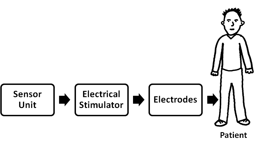 | Figure 2.1. Block diagram of basic FES system |
3. Basic Design
- The stimulator consists of four functional units: microcontroller; power supply unit; output stage; and electrodes. The main unit consists of a microcontroller, for generating stimulation pulses and a push-button for selecting different stimulation patterns and adjusting the stimulation parameters such as frequency, amplitude, and pulse width. [2] Hardware is designed as a general platform that could be used for realization of wide range of possible applications. Basic stimulus controls are provided for each of the two stimulation channels. Figure 3.1 shows the block diagram of programmable and portable FES system.
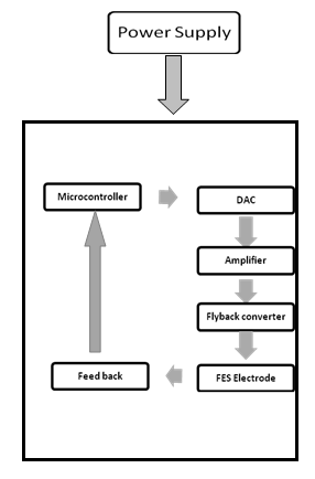 | Figure 3.1. Block Diagram of Programmable and Portable FES System |
3.1. DAC Interface Circuit
- A digital-to-analog converter (DAC0808) is used to convert the programmed digital value into analog value corresponding to the output channel. It is an 8-bit monolithic digital-to-analog converter (DAC) featuring a full scale output current settling time of 150 ns while dissipating only 33 mW with ±5V DC supply. The power supply current of the DAC0808 is independent of bit codes, and exhibits essentially constant device characteristics over the entire supply voltage range.
3.2. Stimulus Signal Generator
- The stimulation signal generator is based on the digital synthesis technique. It is programmed to generate and store four different patterns of stimulus waveforms. A hand held stop switch is also used in the hardware design as a precaution measure. The user or therapist could stop the stimulation in an emergency while using the device. The microcontroller is programmed internally with preset waveform shapes. These digital waveforms are converted to analogue using an 8-bit DAC. The DAC gives waveform amplitudes ranging from 5 mV to 25mV peak-to-peak. This signal is further amplified by an operational amplifier (LM741), which boost this signal to 3V peak-to-peak at the output stage.
3.3. Constant Current Stimulation
- Constant current stimulation is the most widely used technique in FES applications. Almost all the physiological measurements in FES are also performed with constant current. This because of the following advantages:§ Less variability and more stable stimulation due to changes in body impedance Can control the current limit of the pulses for safety e.g. muscle/nerve stimulator, cardiac pacemaker§ Circuits can be built using less number of components
3.4. Power Supply Unit
- The power supply unit provides power for all electronic circuits in the stimulator. The stimulator block provides two channels of stimulus and contains a power conversion block which converts the battery’s of 9 Volts output to 5 Volts. For the negative supplies, a charge pump DC-to-DC voltage converter (TC7660) is used, which converts a positive voltage into a corresponding negative voltage. This is required for DAC interface and thus used to operate the total system by a single 9V power supply. Fly back converter provides supply for the pulse generator module. It converts 5Volt supply into the high voltage range (0-120 Volts) at the output stages, which is required for stimulation in various clinical applications. CMOS integrated chips were incorporated in the FES system design to minimize power consumption. Battery supplied devices are intrinsically safe (the patient is isolated from power supply voltage). The 9 V batteries (e.g. alkaline, DURACELL) can provide the supply voltage to operate the stimulator.
4. Output Stage Design
- The output stage consists of an Op-Amp, and a fly back converter and is shown in Fig 4.1. An LM741 operational amplifier is used, to boost the voltage by 10 times and also used as a buffer to protect any short circuit. The generated pulses from Op-amp drives N- channel MOSFET for enhancing voltage to double and allowing an output power load of up to 10W with about 80% switching efficiency. This MOSFET output drove the transformer. The transformer had 1.2 kΩ input impedance and 3.2Ω output impedance. The squared turns ratio is equal to the ratio of output to input impedances for a transformer, which gives a squared turns ratio n2 =1200/3.2, therefore n = 20 approx. This transformer boosts this voltage pulse by a factor of around 20, to levels at the output for use in the neuromuscular stimulation.
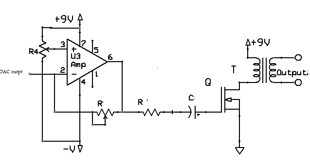 | Figure 4.1. Output stage of FES system |
4.1. Output
- In general, the amplitude of a surface stimulation ranges from 10mA to 150mA, stimulation frequency is between 20 and 40 KHz, and the pulse width is from 150ms to 300ms. The driving stage of stimulator acts as a constant-current source, which is flexible to generate complex electrical waveforms and to boost the electrical pulse voltage to a high level, so that nerves and muscles can be excited by stimulation [4].Previous techniques of FES included primarily hardware control of waveform parameters. There is an evident shift towards complete software control, eliminating problems such as accuracy, unidentified characteristics (e.g. noise, offset), real time response, and efficiency (the device might need to be turned off for hardware fine tuning). We have generated four different types of envelopes that could be applied as versatile application in neuromuscular rehabilitation is shown in Figures.
4.2. Generated Pulses at Stimulator Output
- Initial four types of algorithms (continuous and packets of rectangular pulses, TA EMG pulse shape, and trapezoidal shape) are implemented to generate output envelopes at the system output for drop-foot and for other clinical applications i.e. hand function, shoulder subluxation and knee extension. The clinicians/users have options to choose the suitable pattern for stimulation during treatment. In general, the amplitude of a surface stimulation ranges from 10mA to80mA. The stimulation frequency is between 300 and 40 Hz, and the pulse width is from 200μs to 400 μs.
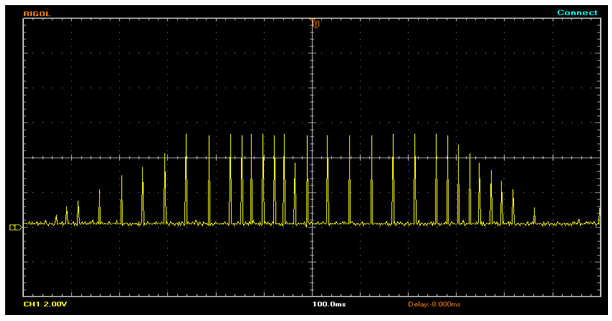
4.3. “Natural TA EMG” Envelope Stimulation
- A “natural” envelope stimulation strategy is proposed based on muscle activation patterns observed in healthy gait. An algorithm is developed to generate a stimulation waveform that is close to the natural EMG pattern of TA muscle with a pulse width of 300 μs, and stimulation frequency of 40k Hz, A single cycle of the generated stimulus output is shown in Fig. 4.2. This specialized stimulation pattern of accurately reproduce the natural TA EMG profile while walking. It provides tetanized muscle contraction for functional movements at ankle and reduces the charge delivery, which is a very important for better functional performance with reduced muscle fatigue. This envelope could be used for the correction of foot-drop in stroke, incomplete SCI and other upper motor neuron diseases (UMNs).
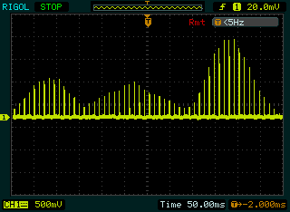 | Figure 4.2. EMG of TA muscle algorithm stimulus waveform |
4.4. Trapezoidal Stimulation Intensity Envelope
- We have programmed an algorithm, which has adjustable delay after heel-off and adjustable extension delay time after heel strike. A single cycle of Trapezoidal drop foot algorithm stimulus waveform is shown in Fig 4.3. The more conventional trapezoidal stimulation intensity envelope is specified by several timing parameters, primarily the ramp-up, extension and ramp-down values. In the correction of drop foot, the clinician may select any one of trapezoidal or natural stimulus envelope.
 | Figure 4.3. Trapezoidal drop foot algorithm stimulus waveform |
4.5. Packets of Rectangular Wave
- This generated stimulation pulse trains is a series of rectangular pulse having pulse width of 300 μs and frequency 40k Hz, which do not appear continuously at the output, but rather in packets of bursts with a duration one second ON and one & half second OFF between successive bursts as shown in Fig. 4.4.
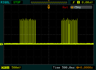 | Figure 4.4. Packets of rectangular stimulus intensity envelope |
5. Control Strategy
- The sensor in the FES system is used to detect the subject’s intentions and to control the train of the electrical pulse from the main unit. The artificial sensors that have been typically used for FES lower limb control included pressure insoles, footswitches and inclinometers. A mechanical switch can be used at the input stage to trigger the stimulation. In a drop-foot stimulator, a foot switch is commonly used for real time application. Based on the feedback system of the FES, controlled electric signals can be given to stroke patients, and hence effective stimulation is obtained. Introducing a foot switch in the sole of the shoes, will lead to save the electrical power and also excess stimulation can be avoided. There are two types of feed backs:1. Foot pressure controlled FES system2. EMG controlled FES system
5.1. Foot Pressure Controlled FES System
- The manual controller is the common way to control the stimulus amplitude. Here the foot pressure is sensed by the piezo electric sensors, and this signal is conditioned, amplified and fed to microcontroller. The block diagram of a pressure sensor FES system is shown in Fig 5.1. As per the instructions in microcontroller the stimulation is controlled in the stimulator circuit, hence an effective stimulation can be given.
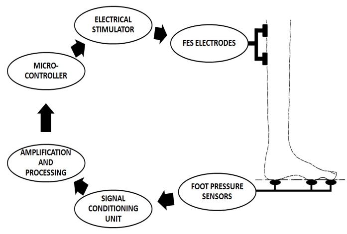 | Figure 5.1. Block diagram of a pressure sensor FES system |
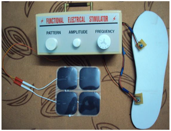 | Figure 5.2. Complete set up of the portable functional simulator |
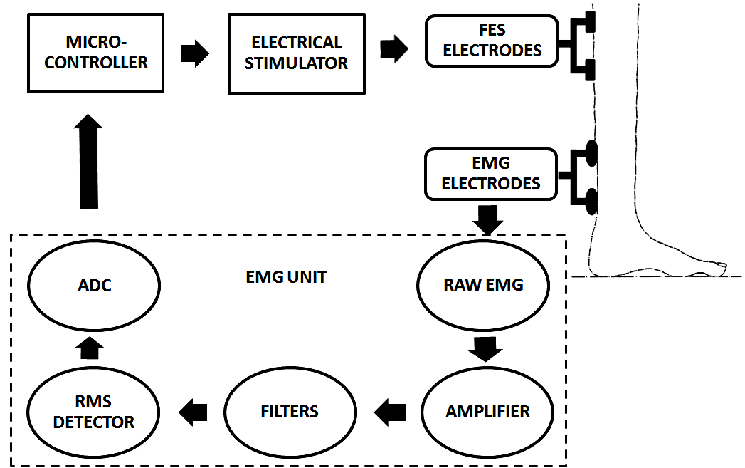 | Figure 5.3. Block Diagram of EMG-controlled FES System |
6. Conclusions
- The programmable dual channel FES system with multi pattern stimulus pulse designed in this paper is useful for both research and clinical applications in the neuro-rehabilitationA prototype microcontroller based foot pressure sensitive FES system is used for correction of drop foot by sensing the foot pressure from the embedded insole of the affected leg during the stance phase of gait cycle and to control the stimulus amplitude automatically at the output during the swing phase of gait cycle. An important need-based objective is to design a functional electrical stimulator using power electronic systems that is portable, light-weight, low cost and user-friendly to operate by the clinician/users. The system is capable to fulfill clinical requirements. The FES device developed is studied in multi-centric clinical studies in order to look for long-term clinical improvement with beneficial results in retraining walking ability and motor recovery functions in stroke rehabilitation.
ACKNOWLEDGMENTS
- The author would like to thank Dr Manjunath Mahadevappa IIT Karaghpur for his kind help and support.