-
Paper Information
- Next Paper
- Paper Submission
-
Journal Information
- About This Journal
- Editorial Board
- Current Issue
- Archive
- Author Guidelines
- Contact Us
International Journal of Internet of Things
2017; 6(2): 15-18
doi:10.5923/j.ijit.20170602.01

Development of Study Model for Automation of Water Pump Using LabVIEW
 Abstract
 Reference
 Full-Text PDF
 Full-text HTML
Franco Aldrin Menezes, Rolen L. Rodrigues
Department of Electrical & Electronics Engineering, SJEC, Mangaluru
Correspondence to: Franco Aldrin Menezes, Department of Electrical & Electronics Engineering, SJEC, Mangaluru.
| Email: |  |
Copyright © 2017 Scientific & Academic Publishing. All Rights Reserved.
This work is licensed under the Creative Commons Attribution International License (CC BY).
http://creativecommons.org/licenses/by/4.0/

In this paper water level monitoring system is developed. Water Level monitoring will help in reducing the home power consumption and water overflow. In this system a water level sensor has been used, which will control the level of water in the tank. When the water level in the tank goes below a predetermined level, the signal will be sent to turn ON the pump and when water level in the tank goes above a predetermined level a signal will be sent to turn OFF the pump. The signals to turn on and turn off the pump are send through sensors via NImyDAQ. The same program is interfaced with LabVIEW. On the front panel of LabVIEW the visual representation of level of water in the tank and motor turning ON and OFF can be graphically visualized.
Keywords: LabVIEW, NImyDAQ
Cite this paper: Franco Aldrin Menezes, Rolen L. Rodrigues, Development of Study Model for Automation of Water Pump Using LabVIEW, International Journal of Internet of Things, Vol. 6 No. 2, 2017, pp. 15-18. doi: 10.5923/j.ijit.20170602.01.
Article Outline
1. Introduction
- Water is a precious resource in many parts of the world and many people rely on water tanks to supplement their water supply by storing collected rainwater or water pumped from a well or bore but measuring of water within the tank is very difficult. Tanks are constructed of opaque material to prevent algae growth and are often kept closed up to prevent mosquito infestation or access by rodents, so it’s inconvenient to physically look inside the tank and measure the level of water in the tank. Besides, having a way to measure tank depth electronically opens up a world of possibilities, such as automatic control of pumps to fill tanks when they get low or to disable irrigation systems when not enough water is available.During these days of high rise Buildings, apartments, Commercial houses and Industries, it has become necessary to store water in overhead water storage tanks. Since water pressure in most localities is not sufficient, water is pumped from ground level tank to overhead tank for storage & use. It is very difficult for someone to monitor water level in ground and overhead tanks and switch ON & OFF water pump accordingly. So a water level controller prevents overflow & dry running of your water pump, thus saves water, electricity & manpower.In this system, to develop a study model we have assembled two buckets which represents the underground tank and overhead tank respectively. The water level in the overhead tank is controlled with the help of relay circuit using the NImyDAQ and LabVIEW interfacing. A water level sensing device in this case is an ultrasonic sensor placed in the upper tank to sense the water level. A pump is placed in the lower tank to pump water to the overhead tank. Whenever the water in the upper tank is beyond the determined level the NImyDAQ and LabVIEW arrangement gives signal to the relay circuit thus turning pump ON and OFF according to the requirement. LabVIEW is used so that the graphical and visual operation can be obtained.
2. System Components
2.1. Ultrasonic Water Level Sensor
- A level sensing device is designed to measure the level of flow substances including liquids, slurries and granular materials [1]. There are also continuous level sensors; these sensing modules can only detect the level of flow of a substance with a specific range.A water level sensor is a device used in the detection of the water level for various applications. Water level sensors are of several types that include ultrasonic sensors, pressure transducers, bubblers, and float sensors.Ultrasonic sensors operate by transmitting sound waves that reflect from the liquid surface and are obtained by the sensor [1]. The sensor measures the time interval between the transmitted and received signals, which is then converted into distance measurement with the help of electronic circuits within the sensor thereby measuring the level of the liquid.
2.2. Relay
- A relay is an electrically operated switch. Relays are used to control a circuit by a low power signal or it can be used to control multiple circuits by using a single signal. When an electric current is passed through the coil it generates a magnetic field that activates the armature and the consequent movement of the movable contacts either makes or breaks (depending upon construction) a connection with a fixed contact as shown in Figure 1 [2]. If the contacts of the relay were normally closed when the relay was de-energized, then when the supply is given to the relay it gets energized and due to this there is a movement because of electromagnetic induction and this opens the contacts which will disconnect the circuit and vice versa.
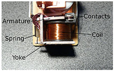 | Figure 1. Relay Construction |
2.3. LabVIEW
- LabVIEW (Laboratory Virtual Instrumentation Engineering Workbench) is a graphical programming language for instrumentation, data-acquisition & analysis, automation & control and communication [3]. LabVIEW is a programming development application, similar to the commercial C/C++, FORTRAN or BASIC development systems. LabVIEW uses graphical programming language, G-programming to create programs allowing the program to be in a "Block Diagram" form. This creates excellent GUI capabilities built-in LabVIEW programs [3].LabVIEW is the software that is used to interface the computer with the control device. Because of the fundamental concepts used in interfacing it is easy to use this tool. The programs written in LabVIEW are called "Virtual Instruments" or VI’s due to the instrumentation-related origin [3]. The programs created are independent of the type of machine that they are created for so programs can be transferred between different operating systems. LabVIEW has a large set of built-in mathematical functions and graphical data visualization and data input objects typically found in data acquisition and analysis applications [4]. Each VI has two components: a block diagram and a front panel. The front panel can be run either as a program, prompting the user for input, or as a function if it is implemented on another block diagram [3]. The advantage of using graphical programming as in LabVIEW is that it avoids the user having to go into the programming aspect of the required action.
2.4. NImyDAQ
- NImyDAQ is a low-cost portable data acquisition (DAQ) device which uses NI LabVIEW-based software instruments, allowing students to measure and analyze real-world signals. NImyDAQ is ideal for exploring electronics and taking sensor measurements. Combined with NI LabVIEW on the PC, students can analyze and process acquired signals and control simple processes anytime, anywhere [3]. NImyDAQ provides analog input (AI), analog output (AO), digital input and output (DIO), audio, power supplies, and digital multimeter (DMM) functions in a compact USB device. There are two analog input channels on NImyDAQ [3]. These channels can be configured either as general-purpose high-impedance differential voltage input or audio input. The analog inputs are multiplexed; meaning a single analog-to-digital converter (ADC) is used to sample both channels. In general-purpose mode, you can measure up to ±10 V signals. There are two analog output channels on NImyDAQ. These channels can be configured as either general-purpose voltage output or audio output. Both channels have a dedicated digital-to-analog converter (DAC), so they can update simultaneously [3]. In general-purpose mode, up to ±10 V signals can be generated. There are eight DIO lines on NImyDAQ. Each line is a Programmable Function Interface (PFI), meaning that it can be configured as a general-purpose software-timed digital input or output, or it can act as a special function input or output for a digital counter. There are three power supplies available for use on NImyDAQ. +15 V and -15 V can be used to power analog components such as operational amplifiers and linear regulators. +5 V can be used to power digital components such as logic devices.NI ELVISmx is the driver software that supports NImyDAQ [3]. NI ELVISmx uses LabVIEW-based software instruments to control the NImyDAQ device, providing the functionality of a suite of common laboratory instruments.
2.5. DOL Starter
- The simplest form of motor starter for the induction motor is the Direct On Line starter as shown in Figure 2. The Direct On Line Motor Starter (DOL) consist a MCCB or Circuit Breaker, Contactor and an overload relay for protection [5].The contactor will be controlled by separate start and stop buttons, and an auxiliary contact on the contactor is used, across the start button, as a hold in contact i.e. the contactor is electrically latched closed while the motor is operating. Contactors are mainly used to control machinery which uses electric motors. It consists of a coil which connects to a voltage source. Very often for Single phase Motors, 230V coils are used and for three phase motors, 415V coils are used [5]. The contactor has three main NO contacts and lesser power rated contacts named as Auxiliary Contacts [NO and NC] used for the control circuit. A contact is conducting metal parts which completes or interrupt an electrical circuit.Ÿ NO-normally openŸ NC-normally closed
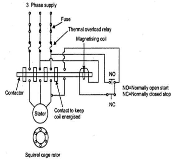 | Figure 2. DOL Starter |
3. Design & Implementation
- In developing the study model for automation of water pump we have used LabVIEW. As LabVIEW is a graphical programming language it is easy for a person with a little technical knowledge to understand and there is no need of skill personnel. The control and monitoring part is done in LabVIEW platform. The acquiring of signals and sending of signals to motor are done by NImyDAQ which is compatible with LabVIEW. The flow chart of the automation of water pump is as shown in Figure 3.
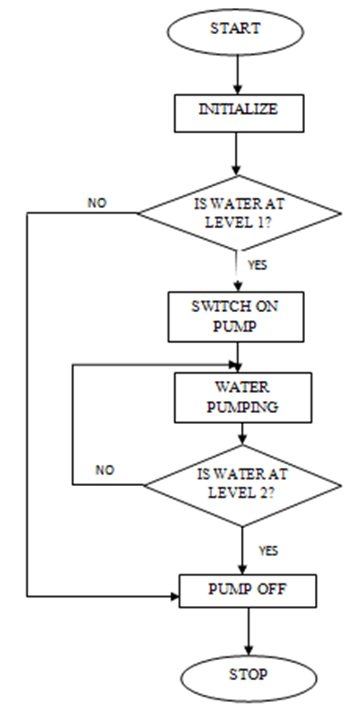 | Figure 3. Flow Chart |
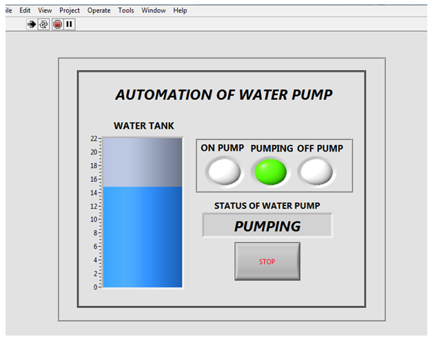 | Figure 4. Front Panel Window |
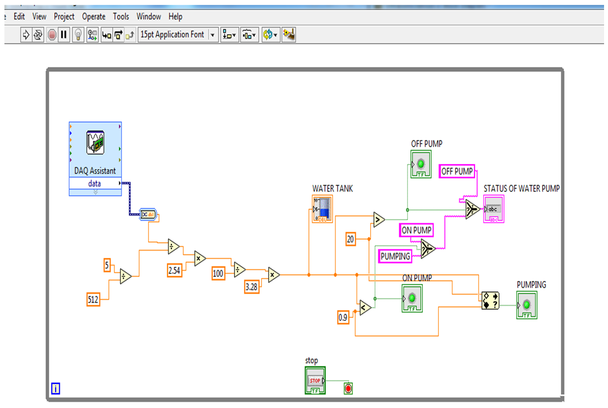 | Figure 5. Block Diagram Window |
4. Conclusions
- The study model of automation of water pump was developed successfully. The system was designed using LabVIEW interfacing with NImyDAQ. The following are the features of the developed model. No Man power required to operate, as the system is fully automatic, the system is easy for installation and it has low maintenance. The developed model is done using the advance technology and it’s simple to use. The model developed has many advantages such has it saves water, motor power and energy. It also avoids seepage of water from roofs & walls due to overflowing tanks. It consumes very low energy and its ideal for continuous operation.
ACKNOWLEDGEMENTS
- We would like to thank the management of SJEC for providing the software and NI components to develop this study model.