Giovanni Saggio , Antonino Lagati , Giancarlo Orengo
Department of Electronic Engineering, University of “Tor Vergata”, Rome, 00133, Italy
Correspondence to: Giovanni Saggio , Department of Electronic Engineering, University of “Tor Vergata”, Rome, 00133, Italy.
| Email: |  |
Copyright © 2012 Scientific & Academic Publishing. All Rights Reserved.
Abstract
Human Computer Interfaces (HCIs) support users to interact or simply control any kind of devices founded on machinery basis. Very simple and common interfaces are represented by mouse and keyboard by which a user interact with the personal computer “machine”. It is however evident how these tools can be particularly “limited” since they “act” only in a 2D superficial environment and cannot provide an immersive experience. So in the latter years new kind of interfaces have been investigated in order to expand the user capabilities in a 3D space, then increasing the realism degree too. In this paper we deal with a new kind of these interfaces. In fact we developed a sensory glove capable to measure all human hand Degree of Freedom (DoF), “translating” them into commands for personal computers. In particular we definedappropriate design rules, and treated details of the signal conditioning electronics surrounding the sensory glove to satisfy the requests of an efficient HCI system.
Keywords:
Human-Computer Interface, User-friendly Man Machine Interface, Sensory Glove
1. Introduction
Bend sensors have been endowed in a Lycra based glove so to furnish electrical signals when flexed by user hand[1]. The overall system of sensors, glove, electronic interfaces and wireless part, form the so called sensory glove (also known as data glove or instrumented glove), which we referred here with the term of HITEG-Glove since our group name (Health Involved Technical Engineering Group). In addition a virtual environment has been created so to give to the user a useful real-time visual feedback via ad-hoc avatar to his/her actions.The measured movements of an user hand furnish electrical signals that we converted into pc actions, such as movingthe cursor in a virtual 3D space, opening/closing applications, playing virtual instruments or even creating or assembling virtual objects (see Fig. 1). For the latter case the hand avatar reproduce exactly all the user hand movements, i.e. flex-extension, abdu-adduction of finger movements, wrist angular positions.In the past different sensory gloves have been already developed by other research groups, but this paper intends to furnish a new methodology to investigate the properties of the bend sensors, to define requirements for the electronic circuitry including its wireless part, to propose a circuitry solution in order to profit by the very final sensitivity properties of the bend sensors and, finally, to suggest tools and procedures to realize a very accurate avatar representation via video based framework of recorded hand movements (see Figs. 1, 10, 11).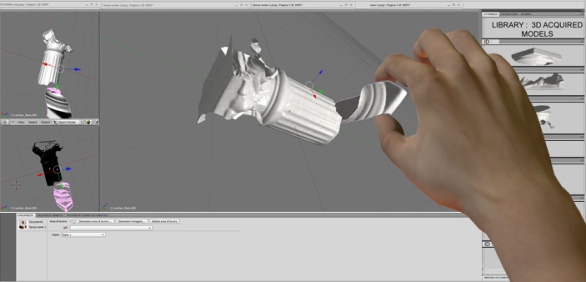 | Figure 1. Hand movements recorded by the data glove are real-time reproduced via avatar. 3D interaction to assemble 3D virtual objects |
2. Materials
In order to realize one prototype of a sensory glove we could choice among different sensors since, over the time, different kind of sensors have been successfully adopted for different sensory gloves, both commercial and non-commercial ones.Among the commercialized products we can mention the 5th Glove (Fifth Dimension Technologies, Irvine, CA), the CyberGlove® (Immersion Corporation, San Jose, CA), the HumanGloveTM (HumanwareSrl, Pisa, Italy), the P5 Glove (CyberWorld, Montreal, QC, Canada), the ShapeHand (Measurand, New Brunswick, Canada).As research products there are the TUB-Sensor Glove (Technical University of Berlin), the Sigma Glove (Sheffield University), the Washington University Glove and the Accele Glove (Washington University), the Acceleration Sensing Glove (Berkeley University), and the WU Glove (University of Wuerzburg, Germany).The sensing technology can be based on optical devices (fiber optics[2], optical linear encoders[3]), acoustic devices (as in the Power Glove by Mattel), inertial devices (accelerometers[4], gyroscopes[5]), magnetic devices[6], electromagnetic devices (Hall effect, see HumanwareSrl, Pisa, Italy), electrical devices (bend or flex sensors[7],[8],[9]) etc. On the basis of different sensing technology, different types of sensors can be utilized, so that different sensory gloves can be realized and investigated.The HITEG-Glove here presented is mostly based on bend sensors capable of measuring bending angles thanks to their capability to convert a mechanical bending into an electrical resistance variation.We measured performances of several bend sensors, manufactured by Flexpoint Sensor System Inc. and Image S.I., different in length and encapsulation materials.
3. Methods
3.1. Characterization of the sensors
The first fundamental step is to measure the resistance value vs. bending angle pairs, so to evaluate the bend sensor performances to correctly utilize them in a sensory glove.The measures on the sensors can be performed both “on-line” and “off-line”. The “on-line” is intended as a method of measurements performed directly with the sensors already embedded in the glove and the glove donned by a tester[2] or by a dummy hand[10]. The “off-line” is intended as a method to measure the sensors prior to insert them into the glove, and it is usually performed with a procedure based on a traditional goniometer to measure the corresponding sensor outputs of a few bending angles. The “on-line” method is the most adopted one because treats the final performances of the overall system, but only with the “off-line” method we believe that it is possible to determine the real intrinsic properties of the sensors, since their performance inevitably get worst when used in a glove. We found that the measures obtained by the “off-line” method can be generally worsened because of human factors such as the operator’s expertise. So, here we propose a fully-automated method for “off-line” measurements.We characterized the sensors in their resistance variation vs. bending angle thanks to an indigenously designed and fabricated set-up, based on hinges where the sensors lay on, and a stepper motor which provides the rotation of one wing of the hinge (with respect to the other which is fix constrained), simulating a human finger joint rotation, as shown in Fig. 2.The adopted motor, necessary for the movement imposed to the rotating wing, was a Trinamic PD-109 two phase hybrid stepper, microstepping optimized. It was provided with a Trinamic Motion Control Language (TMCL) which consists of an instruction set of motion control commands. On the basis of a host computer PC based software development environment, the TMCL-IDE, motion control commands were given to the motor. A rigid frame provides the necessary stability to the system. The motor was fixed on an optical bench by angular Newport EQ80-E shores. The motor motion was transmitted to the hinge’s axis thanks to an universal rigid joint in order to obtain an excellent stability. For testing a sample, an hinge’s wing was fixed on the structure, while the other wing was free to be moved by the motor.With this measurement set-up, each sensor could be characterized in a -90° to 180° (from inward to outward) range for programmable step value of bending angle, number of measurement repetitions and mechanical actuator speed. At known angles, the resistance values of the sensors are measured by an Agilent 34405A multimeter[9, 11].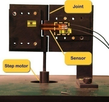 | Figure 2. Experimental set-up for macroscopic bending measurements: it is designed to simulate the human finger joints kinematics |
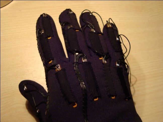
The investigated bend sensors have a large measurement range for outward bending from 0° to 150°, and correspondingly the resistance normally changes from 15 to 440 kΩ. The sensors manifested a really negligible hysteresis and a good repeatability of the measures. Among all the performed measurements, some relevant results are showed in Fig. 3.We performed measurements of resistance mean values and standard deviations, on 6 different 3 inches length polyimmide encapsulated Flexpoint sample sensors: each sensor was characterized repeating measurements 10 times, varying bending angle from 0° to 150° and return.After the characterization, the sensors were mounted on a Lycra based glove, one sensor for each finger joint (see Fig. 4).The resistance variation vs. bending angle characteristic of each sensors was utilized to correctly convert the electric resistance value into the corresponding finger joint flexed angle.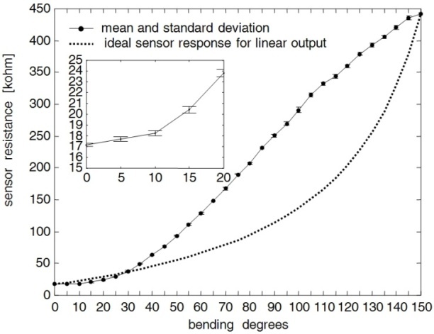 | Figure 3. Resistance variation vs. bending angle: mean and standard deviation. Ideal sensor resistance for linear output (dotted). Detail of low bending angles (small window) |
 | Figure 4. A sample line graph using colors which contrast well both on screen and on a black-and-white hardcopy |
3.2. Design of the Electronic Circuitry
The measured electric resistance signals, coming from the sensors, were then conditioned, recorded and sent to a receiving location for further exploitation.For the electronic interface and the signal conditioning circuitry we found generally convenient to have:• a sufficiently large resistance variation for sensors;• good “robustness” for the circuit, because there is more noise in wearable applications, consequently, direct resistive sensor-to-microcontroller interfaces are not strongly suggested;• a simplified circuit structure for smaller size;an integrated and removable battery;• a very low power consumption, to get a longer service time in which a continuous monitoring can be applied without battery replacement or recharge;• comfort to wearers for user activities.This is why we report here a solution we adopted as convenient for the previous requirements for a sensory glove system. A novel approach for analog signal conditioning before A/D conversion, which matches the requirements is presented. System configuration, accuracy and resolution have been analyzed in-depth and design rules have been defined.Experimental results showed that this electronic interface exhibits less than 1% error in a large measurement range for bend sensor rotation angle. It also showed a good stability to power supply interference. The interface has been successfully applied to a glove-based measurement system of hand gesture.The optimized electronic interface for sensors here concerned was based on a differential instrumentation amplifier. Fig. 5 schematizes the proposed electronic interface.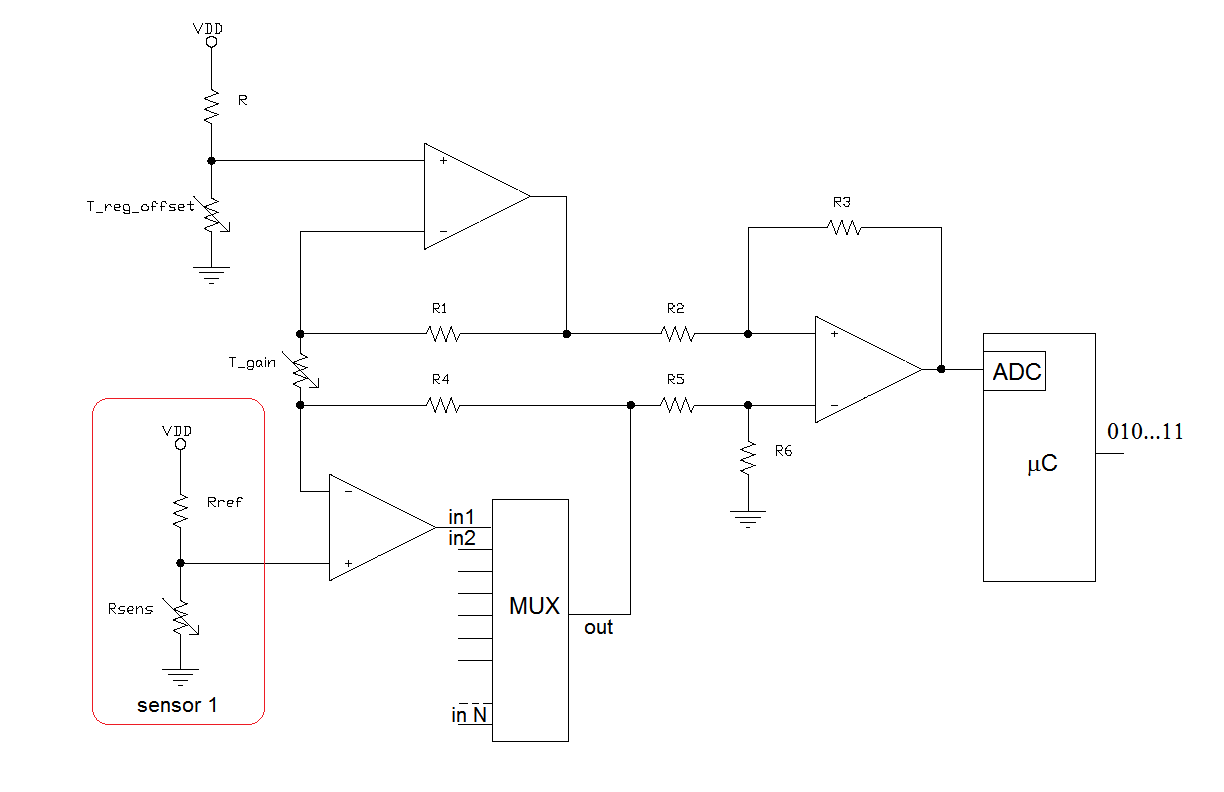 | Figure 5. Signal conditioning electronic interface proposed |
It consists of a group of voltage dividers for each resistive sensors, so to extract a voltage signal from sensor resistance variation using a first stage input buffer. Subsequently a second stage provides to properly shift/amplify the sensor signals with the possibility of finely adjusting both gain and offset level to make the levels of output voltage dividers fit the input range of a PIC microcontroller 12 bits A/D converter. This was our added value, because, in this way, we could profit by the very sensitivity properties of the bend sensors, recordingreasonable meaningful signal variation corresponding to very little joint bending.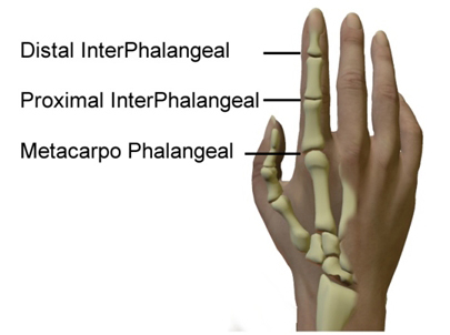 | Figure 6. Human finger joints |
Then the microcontroller sent the digital signals in serial form to a general purpose PC for post elaboration, reconverting them to the corresponding bending angles of the joints. Voltage dividers were used because of their simple structures and potential high dynamic measurement ranges they can furnish. In order to minimize the size of the electronic interface, a single conditioning circuit of the signal, which could be used by every sensor implementing a polling routine on a multiplexer, was designed. It is important to notice that the voltage signal variation range varies from sensor to sensor; this is because the technological process of factory doesn’t produce identical devices (as it results clear by observing the standard deviation reported on the seven calibration points of the characteristic curve reported in Fig. 3). Another reason is that the maximum bending angle of each sensor depends on the joint it is applied to; for example the sensors of the Proximal InterPhalangeal joints (see Fig. 6 for reference), which perform the maximum bending angle possible (typically 120° in a wholly able subject), react with the largest resistance variation.For such reasons it was necessary to choose, in designing the instrumented differential amplifier, a voltage gain (and a level shift) which have to be the best match in order to make the signals of all the sensors fit the input range of a PIC microcontroller 12 bits A/D converter. Considering a single voltage divider (represented in the box left in Fig. 5), a significant issue in the design is how to set Rref.The single element has the following voltage divider: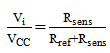 | (1) |
so, after a 120° bending: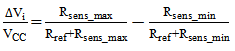 | (2) |
where Rsens_min corresponds to 0° bending, whereas Rsens_max to 120° bending, which is the maximum allowable flection of a finger joint and  to the consistent voltage variation.In order to maximize the signal sweep for the maximum allowed flection degrees, the voltage divider resistance Rref can be yield nullifying the corresponding partial derivative:
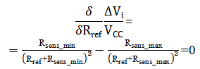 | (3) |
to obtain: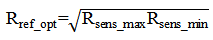 | (4) |
which corresponds to the geometric mean of the extreme sensor resistance values. If the sensor bending sweep is not always the same, an optimized reference resistor for each sensor has to be chosen.The normalized voltage signal variation coming from each sensor becomes: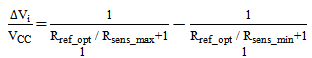 | (5) |
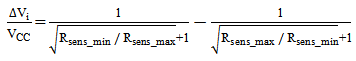 | (6) |
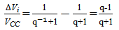 | (7) |
where: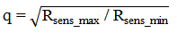 | (8) |
The equation 7 provides the maximum voltage divider signal variation with the optimized value for Rref_opt.Furthermore it can be seen that a bend sensor exhibiting the largest sweep in resistance for a given bending angle is required, because even if this sensitivity is smoothed from the root.This is the reason why we preferred in this project the Flexpoint bend sensors (q2=20) over those from Image (q2=6), as it is represented in Fig. 7, where the voltage divider sweep is plotted against the choice of the reference resistance for different q values.
 | Figure 7. Normalized voltage divider output sweep vs. reference resistor value |
When used inside a voltage divider, sensor response linearity does not depend upon linearity of sensor resistance. This can be easily seen in Fig.8, where the measured voltage response resulting from the voltage divider is plotted for different values of the reference resistance, whereas the dashed plot represents that one corresponding to the optimized reference resistance in accordance to (4).As it can be seen, the voltage response is misleading for low bending angles. On the other hand, the dotted plot is referred to an ideal (linear) voltage response, which could be obtained if the sensor resistance response would be the one also plotted in Fig.3.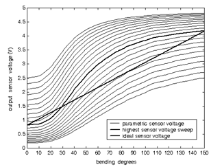 | Figure 8. Parametric sensor voltage output (parameter Rref), highest voltage sweep (Rref_opt) (dasehd line) and ideal (linear) voltage output (dotted) |
3.3. ADC Resolution
Further investigation was required to set the appropriate resolution for the A/D converter inside the microcontroller. Naming Vni the noise coming from the signal conditioning circuits and Vnq the quantization noise, where: | (9) |
It can be seen that the resolution N can be chosen from the following inequality: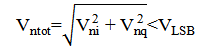 | (10) |
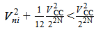 | (11) |
 | (12) |
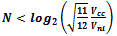 | (13) |
Since the rms noise measured at the output of the signal conditioning circuits is Vn=2mV, the above equation yields N<11.On the other hand, to guarantee a one degree resolution even for small bending angles, corresponding to 5 mV output voltage in the characteristic plotted in Fig.8 without signal conditioning circuits, the required number of bits is given by: | (14) |
Since the embedded A/D converter has 12 bit, the above mentioned conclusions allow the PIC to force 5 LSBs to zero.
3.4. Wireless Connectivity
For the sensory glove wireless connectivity, some requirements are mandatory:●it must guarantee human safety;●it has to assure a reasonable data rate;●it has to cover a reasonable distance (range of transmission);●it has to have low power consumption (for long life battery powered devices) and low transmission power (to reduce effects of radio signals to the body);Some other requirements are preferable but less stringent:●it is convenient to adopt an international standard●it is preferable to be self-configurable for more data gloves (or other dresses provided with sensors) at timeFor all these reasons the connection between the micro controller and the computer for elaboration was realized using a MRF24J40MA transceiver (see Fig. 9) which support the ZigBee protocol for Wireless Personal Area Network (WPAN) development[9].ZigBee is a low-cost, low-power, wireless mesh networking standard based on IEEE 802.15.4 definitions of Physical and Medium Access Control layers (PHY / MAC).By using the information provided by the datasheet of the Chipcon CC2420/ZigBee, we computed the power Pd dissipated by a single Tx/Rx device. Assuming the utilisation of a battery PP3 (9V), with a capacity Cb of 500 mAh (equivalent to 16200 J) and a constant discharge, assuming a continuous monitoring, the expected battery lifetime is 3 days (see[9] for details), which can be considered a suitable value for our purposes.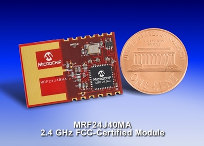 | Figure 9. The adopted MRF24J40MA transceiver used for HITEG Glove wireless communication |
3.5. Avatar Representation
We realized a very accurate avatar representation via video based framework of recorded hand movements.Once data were correctly acquired and converted into digital form, all values were sent to PC with a specific protocol useful to disambiguate and recognize the exact sensor under investigation (among all the 15 adopted, one at time) and its value. So the data were tidily stored in a specific MySQL database, one record for each sensor, one field for each recording time. In such a way data can be useful re-called and utilized in simple numerical format or, more effectively, utilized to replicate the real hand movement by a virtual avatar on a PC screen. With this aim, it was realized a Graphic User Interface (GUI), programmed in C++ language, by means of Windows Application Program Interfaces (API) and DirectX 9.0c. The software converted digital values into bending degree values for each finger joints and represented all postures on a graphical body model.A complete 3D body model was realized starting from Blender, which is an open source multiplatform software. In order to animate the model mesh and make it move, translating real human actions to virtual actions in the simulated environment, we defined an armature which is made of a series of invisible bones connected to each other via parenting or constraints, that allow us to pose and deform the geometry that surrounds it, in this case the mesh.The armaturewas used for building skeletal systems to animate the postures of characters and anything else which needs to be animated (see Fig.10, A and B).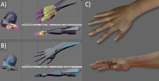 | Figure 10A. 3D human hand model: A) Mesh with vertex group (yellow selection); B) Armature: hidden hand bones; C) Final rendering of the rigged model with textures and lights |
The armature modifier allowed objects to be deformed by bones: as a bone moves, it deformed or moved the vertices (single points of a mesh) associated with it. The mesh surface is analogous to the skin of the human body. The armature is also called Skeleton. There were various great advantages from the utilization of 3D virtual model of the hand.During the pre-processing data phase, the model was utilized as a support tool to qualitatively verify the measurement repeatability. During the real-time visualization phase, the model allowed the hand visualization from different points of view, a continuous monitoring of the coherence of data streams and a rapid re-calibration if necessary.During the post-processing data phase, thanks to the model, it was possible to replay all the fingers movements in slow / rapid / frame-by-frame motion and to isolate even just one finger at a time, removing the others from the view, in order to focus the operator’s attention only on some important details (see Fig. 11).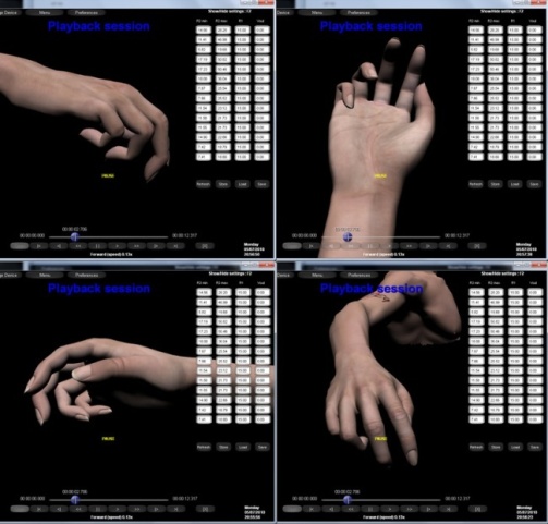 | Figure 11A. reproduction session: software allows user to see an acquisition session off-line, and by rotating 3D model in any direction, it is possible to analyze reproduction from different viewpoints |
4. Conclusions
We designed, realized and tested a complete sensory glove system for realizing Human Machine Interface not limited to 2D dimensions as the common pc interfaces are.We definedappropriate design rules for the overall system, i.e. “off-line” characterization of the sensors, added values for the electronic circuitry, tools and procedures to realize a very accurate avatar representation via video based framework of recorded hand movements.The system was successfully utilized for HCI in 3D virtual environments, in particular to interact with virtual objects. We believe this work can furnish the basis to improve new interaction possibilities not only with virtual environments, but with real machines too.
References
| [1] | Dipietro L., Sabatini A. M. and P. Dario, “A Survey of Glove-Based Systems and their Applications” IEEE Transactions on Systems, Man, and Cybernetics-Part C: Applications and Reviews, vol. 38, no. 4, July 2008. |
| [2] | Wise S, Gardner W, Sabelman E, Valainis E, Wong Y, Glass K, et al. Evaluation of a fiber optic glove for semi-automated goniometric measurements. J Rehabil Res Dev 1990;27(4):411–24. |
| [3] | Li K, Chen I-M, Yeo SH, Lim CK, Development of finger-motion capturing device based on optical linear encoder, Journal of Rehabilitation Research & Development, Volume 48, Number 1, 2011, Pages 69–82 |
| [4] | Hernandez-Rebollar J. L., Kyriakopoulos N., Lindeman R.W., The AcceleGlove: A whole-hand input device for virtual reality, in Proc. SIGGRAPH, 2002, p. 259 |
| [5] | Soh B. S., Kim Y. S., Lee S. G., Improving the usability of a wearable input device SCURRY, presented at the Int. Conf. Ubiquitous Comput., Nottingham, U.K., 2004 |
| [6] | Mitobe K, Kaiga T, Yukawa T, Miura T, Tamamoto H, Rodgers A, Yoshimura N. Development of a motion capture system for a hand using a magnetic three-dimensional position sensor. Boston (MA): ACM SIGGRAPH Research posters: Motion capture and editing; 2006 |
| [7] | Simone LK, Sundarrajan N, Luo X, Jia Y, Kamper DG, A low cost instrumented glove for extended monitoring and functional hand assessment, Journal of Neuroscience Methods 160 (2007) 335–348 |
| [8] | Gentner R, Classen J, Development and evaluation of a low-cost sensor glove for assessment of human finger movements in neurophysiological settings, Journal of Neuroscience Methods 178 (2009) 138–147 |
| [9] | G. Saggio, M. De Sanctis, E. Cianca, G. Latessa, F. De Santis, F. Giannini “Long Term Measurement of Human Joint Movements for Health Care and Rehabilitation Purposes” Wireless Vitae09 - Wireless Communications, Vehicular Technology, Information Theory and Aerospace &Electronic Systems Technology, Aalborg (Denmark), 17-20, pp. 674-678, May, 2009. |
| [10] | N.W. Williams, J.M.T. Pensore, C.M. Caddy, E. Barnes, D.R. Hose, P. Harley “A goniometric glove for clinical hand assessment”, Journal of Surgery (British and European Volume 2000) 25 B: 2: 200-207 |
| [11] | G.Orengo, G.Saggio, S.Bocchetti, F.Giannini, “Advanced characterization of piezoresistive sensors for human body movement tracking”, IEEE International Symposium on Circuits and Systems (ISCAS), Paris, pp.1181-1184, May 2010. |
 Abstract
 Reference
 Full-Text PDF
 Full-Text HTML