Omid Saberi1, Pål-Tore Selbo Storli1, Knut Alfredsen2
1Department of Energy and Process Engineering, Norwegian University of Science and Technology Faculty of Engineering, NTNU
2Department of Hydraulic and Environmental Engineering, Norwegian University of Science and Technology Faculty of Engineering, NTNU
Correspondence to: Omid Saberi, Department of Energy and Process Engineering, Norwegian University of Science and Technology Faculty of Engineering, NTNU.
| Email: |  |
Copyright © 2021 The Author(s). Published by Scientific & Academic Publishing.
This work is licensed under the Creative Commons Attribution International License (CC BY).
http://creativecommons.org/licenses/by/4.0/

Abstract
In this paper a new way has been suggested to address operational restrictions in hydro power plants with outlet to rivers by a technical installation called “Air Cushion Underground Reservoir”. This is an excavated, air pressure regulated storage volume for the water in connection with the tailrace tunnel. ACUR has been designed to control the net flow into the river, making it possible to address today´s environmental restrictions but significantly increasing operational flexibility because power generating flow through the unit and discharge to the river is temporarily decoupled. Also, this system can be utilized to control pressure waves and store excess liquid in the hydropower plants as a closed surge tank system. To evaluate impact of this system on the hydroelectric power plants and rivers, the Norwegian river Nidelva, and the power plant Bratsberg has been selected and modelled with different scenarios. The results confirm that the ACUR can decouple the production flow and the discharge to the river, increasing operational flexibility while still providing the required environmental flow.
Keywords:
Hydro power plants, Air Cushion Underground Reservoir, ACUR, Operational flexibility
Cite this paper: Omid Saberi, Pål-Tore Selbo Storli, Knut Alfredsen, New Technology to Increase Hydropower Plant Operational Flexibility, International Journal of Hydraulic Engineering, Vol. 10 No. 1, 2021, pp. 1-7. doi: 10.5923/j.ijhe.20211001.01.
1. Introduction
During the last century growing population and economy has increased the demand for energy. Suppling this energy is one of the biggest challenges for all countries. Among all energy sources hydropower plants are very desirable. The main reasons are related to high efficiency, high specific power, flexibility on short and long timescales, less climate impacts due to low carbon emissions, sustainably and having lower price compared to other energy sources as illustrated in the Figure 1. [1], [2].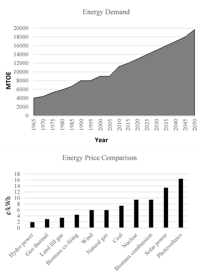 | Figure 1. Energy Demand [1] Energy price comparison [2] |
The most flexible hydropower plants in the world are classified as high head hydroelectric power plants with an upper reservoir [5]. These hydroelectric plants convert the water’s potential energy to electric energy by allowing water to be pulled by gravity thorough tunnels, pipes and turbines, the water ending up at a lower elevation. This might be a natural lake, the sea, a reservoir or a river [6]. Despite the many advantages of these highly flexible, high head hydropower plants, at many locations there are environmental concerns related to discharge fluctuations. These cases are typically related to power plants where the discharge of water goes into a river. At many locations there are operational restrictions imposed to limit the negative impacts of highly fluctuation discharge into the downstream river. This limits the performance and of those intrinsically flexible hydropower plants. The key problem is that production flow is coupled to discharge into the river in an almost one-to-one relation. What goes through the turbines are almost without delay going into the river. This paper will present novel ideas on how to achieve a new way for decoupling hydropower outflow to the river. This freedom is linked to the active control of the displacement of water by compressed air in different configurations. The objective of this paper is to present and verify the concepts of this new tech. The motivation of the authors is stimulating the development of new technical solutions that will increase the actual flexibility of hydropower plants that technically are very flexible. For this reason, this paper is not presenting a technology with a high level of detail, rather presenting the intended outcome of such a technology. Work is currently being performed trying to bring the concept to a higher Technological Readiness Level (TRL), and no major obstacles have been encountered making the projection for future outcomes in this paper void.
2. Air Cushion Underground Reservoir
ACUR has been suggested by one of the authors in a previous paper [3]. This technology is in the intersection point of constructive and operational measures as it is a hydraulic structure that will partially lift the limitations regarding power plant operation. With intended use of ACUR, limitations considering the change of discharge flow can be averted, as the discharge to the river will be decoupled from the flow through the turbines in critical periods of large changes in the discharge. This decoupling is made possible through an excavated chamber, compressor and valve system. The ACUR storage element is an excavated cavern which is filled with water and pressurized air. This, in turn, is linked to the tailrace tunnel on one side, and an air system incorporation a compressor on the other side. Controlling the air pressure gives control over whether water goes in or out of the ACUR storage element. This ultimately becomes control of the discharge to the river. Therefore, the discharge going in or out of the ACUR can dampen the fluctuations and decrease the rapid changes in the discharge to the river as illustrated in the Figure 2. [4]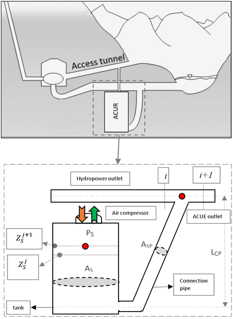 | Figure 2. ACUR system |
Rapid changes to hydropower plant outflow are mitigated by the ACUR system based on a discharge target to the river, which can be decided on considering environmental issues for the downstream river and store this extra water in a storage element between turbine and the outlet. This mechanism is indicated in Figure 3.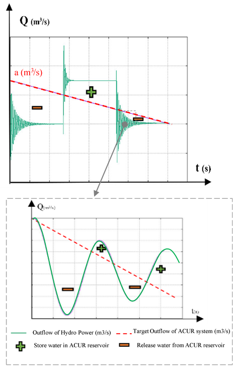 | Figure 3. ACUR mitigating outflow fluctuations |
In this way, the potential flexibility intrinsic to the hydropower plant technology is made real, without the conventional impacts on the environment. In fact, the ACUR system will improve on both aspects; increasing the real flexibility of the plant as well as improving the ecological state of the river compared to current regime. [14] Figures 2 and 3 show the ACUR system mechanism for mitigating hydro power outflow and increasing operational flexibility.
3. Case Study: Bratsberg Hydropower Plant
To evaluate the impact of the ACUR system on the hydroelectric power plants and rivers, the Bratsberg power plant have been selected. It has an outlet to the river Nidelva, which traditionally has been an important river for salmon fishing in the region. Norway has a responsibility for protecting the Atlantic salmon (salmon salar) [16], and this river has been subject to a lot of research on salmon in most of its phases of life [17]. The project funding the presented research (H2020 HydroFlex) chose Nidelva as a case study due to the extensive set of data and knowledge existing for this river [15]. The main objective of HydroFlex is to increase the flexibility of hydropower technologies while mitigating environmental impacts. The authors would like to highlight that Bratsberg power plant is characterized by a head that is lower and a discharge that is higher than what ACUR initially was intended for. The idea of ACUR emerged with higher heads and lower discharges (lower specific speed turbines) in mind. In the case of Bratsberg, the consequence is that the required volume is very large, and one might deem this unfeasible by economic arguments. However, keeping in mind that the ACUR system is intended for plants with smaller discharge and thus a less volume required, the results presented will still prove valuable.Bratsberg hydropower plant has been producing energy since 1977 and located in Trondheim, Norway. Two Francis turbines has been installed on this hydro power plant and the maximum discharge of each turbine is 60 m3/s. the water height at the reservoir is 155.0 m. The length of head race tunnel is 12000.0 m and outlet tunnel 2100.0 m, two surge tanks has been installed in this hydro power plant, the first one is located at the end of head race tunnel and second one at the beginning of outlet tunnel. The ACUR system has been considered at the outlet of this hydro power plant after second surge tank. The detailed layout of the power plant is confidential, but the time constant Tw, indicating the acceleration time, and thus the inertia of the water masses in the system is calculated as shown in the Equation 1: [4]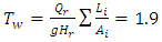 | (1) |
Here: Qr and Hr are turbine flow and net head and Li and Ai are length and cross section area of the water passage. The hydropower plant is by-passing a rather long section of the original river, and an environmental flow in this bypass reach is maintained at 30.0 m3/s, adding to the outlet flow from Bratsberg providing the flow in the lower parts in the river. So, when the Bratsberg power plant is shut down, there is still 30.0 m3/s in the river as illustrated in the Figure 4.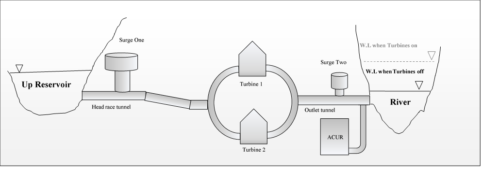 | Figure 4. The Bratsberg Hydro power plant |
4. Methodology
The methodology of investigating the system with the ACUR system added is by simulations utilizing the Method of Characteristics (MOC) in an in-house code [11]. The dynamic response of the system has been verified by using analytical formula for pressure reflection times and u-tube oscillations, confirming the performance of the code for both elastic and non-elastic dynamic responses. All important elements are included in the model, but no effort is made in including a detailed turbine model as the simulated cases will be fast shut-down, and fast start-up. Prior to start simulations including the ACUR system, some input is needed. These are the target for the discharge to the river and the plan for operation of the power plant. In the following these inputs are explained in more details:
4.1. Target Outflow
The aim for what the discharge to the river should be, the target outflow, must be decided. This is an input to the river discharge at a point in the river, and in modelling of river flow this is called a hydrograph. This input has been provided by others in the HydroFlex project, namely Prof. Kut Alfredsen and his team. Their investigations have looked at the reduction in flow rate of the river at the point of the outlet of Bratsberg in order to have a water surface level decline of less than 10.0 cm/hour when the riverbed is starting to emerge. This limit is based on previous research showing that if the water level is decline faster than this there is an imminent danger of fry and parr being stranded in small pools forming on the river bed, thus eventually dying when the ponds disappear as the water table decline or being eaten by predators. These investigations have shown that there is no danger for stranding when the river flow is higher than 105 m3/s. This means that the hydropower plant can operate without limitations due to environmental issues for discharge higher than 75.0 m3/s. For powerplant discharges lower than this the limitations due to water level reduction rate becomes important, and the reduction in flow from 75.0 m3/s to 0.0 m3/s should occur over a duration of 4.5 hours. This will then be the target hydrograph for the system with ACUR, which can be seen in Figure 5. 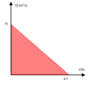 | Figure 5. ACUR target outflow |
According to the Figure 5, it is expected ACUR decoupling the Bratsberg out flow at the shutdown situation from 120.0 m3/s to 75.0 m3/s and increase shut down time from 30.0 s to 4.5 hours without influencing on hydropower plan efficiency.
4.2. Standard ACUR and Hydropower Operation Plan
In this part, operation plan of the hydro power and ACUR system must be defined and it is recommended, proper operation plans must be considered for the hydropower and ACUR system. For this case study, following operation plans has been considered (Figure 6): 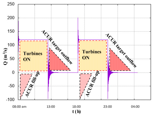 | Figure 6. The ACR and Bratsberg operation plan |
Figure 6 shows, both turbines at the Bratsberg hydropower are started to work from 8:00 am till 01:00 pm, after that hydropower goes shutdown till 06:00 pm then both turbines back to work from 06:00 pm till 11:00 pm, also the Bratsberg hydropower plan uses 30.0 s from zero to full production and 30.0 s from full production to completely shut down situation. For the ACUR system standard operation plan has been selected. In this operation plan the ACUR system start to fill-up reservoir immediately after turbines are turned on (08:00 am and 06:00 pm) then the ACUR start to release water immediately after all turbines go shutdown (01:00 pm and 11:00 pm). In the following results of the ACUR system for the Bratsberg hydropower are presented in more details:
5. Results and Discussion
5.1. Reservoir Volume Results
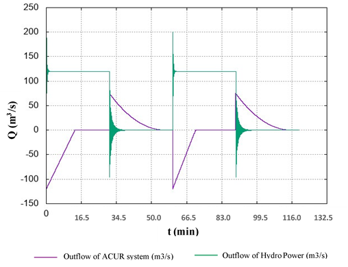
In order to determine a best value for the ACUR reservoir volume, following assumption has been made:- Shape of the ACUR target outflow hydrograph is modified by using two different shapes (Curve and break lines) and all results are compared against each other’s.- The primary shapes for the ACUR reservoir have been considered as cylinder and for a better comparison between results, area of the ACUR reservoir in all scenarios have been kept constant at 122000.0 m3. Figures 7 till 9 show the ACUR system have to fill-up the reservoir in all scenarios when the hydropower is started.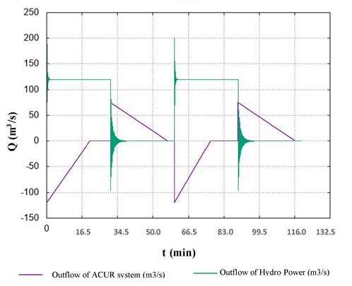 | Figure 7. Outflow results for Linear scenario |
 | Figure 8. Outflow results for Curve scenario |
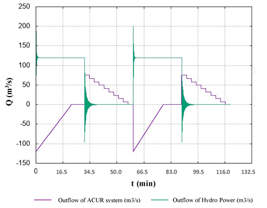 | Figure 9. Outflow results for Break lines scenario |
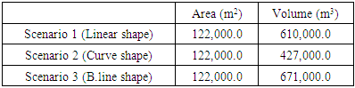
The ACUR reservoir volumes have been determined based on the target outflow hydrograph shapes as illustrated in the Table 1:Table 1. ACUR reservoir volume
 |
| |
|
Table 1 shows different scenarios has significant influence on the ACUR reservoir volume and the curve shape (scenario 2) reduced the reservoir volume more than Linear and break line shapes.
5.2. Optimize Reservoir Volume (New Operation Plan)
It is possible to reduce volume of the ACUR reservoir by applying a new method. In this method, standard operation plan of the ACUR system are modified by overlapping the target outflow hydrograph on the hydropower operation plans.By overlapping two operation plans as shown in the Figure 10-b, four shapes are created, but only in one certain point the volume of the shapes 1 is equal to the shape 2 and this specific point (t) is a start point of the ACUR system for releasing water (the new operation plan).This new operation plan improves the efficiency of the ACUR system, and it will make the ACUR system become more flexible and it can be installed on verity type of hydro power plants. In the following figures this process is illustrated in more details (Figure 10 a, b).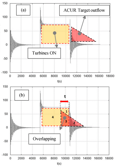 | Figure 10. Concept of the new ACUR operation plan |
Now, by applying new operation plan (Figure 10-a and 10-b) on the scenario 2 of the ACUR outflow (Figure 8), new results are obtained as shown in the Figure 11: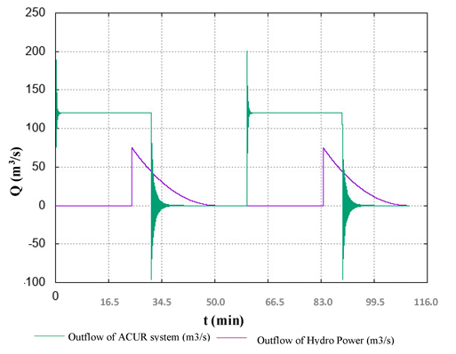 | Figure 11. Optimized ACUR results for Curve scenario |
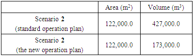
Figure 11 shows the new operation plan doesn’t need to fill-up process (unlike the standard operation plan) and the reservoir fill-up and release process have been performed at the same time.Now, by comparing results of both operational plans (Figure 8 and Figure 11) it is reveals, the ACUR volume has been reduced more than 60% by using the new ACUR operation plan as illustrated in the Table 2.Table 2. Comparing Scenario 3 results
 |
| |
|
Table 2 reveals, proper operation plan has significant influences on the ACUR reservoir volume reduction.
5.3. Pressure Results
After calculating the ACUR reservoir volume (Table 2), the pressure corresponding to this volume can be determined based on the ACUR connection pipe length and water levels in the reservoir (Figure 2). In this case study it is assumed the ACUR reservoir has been located 20.0 meter under the Brastberg outflow hydro power (length of the ACUR connection pipe is 20.0 meter), therefore, the pressure at the reservoir regarding to the water level and depth has been calculated as shown in the Figure 12.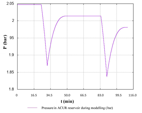 | Figure 12. Pressure for Curve scenario at 20.0 m depth |
Figure 12 shows, the ACUR system need pressure around 2.0 bar to mitigate outflow of the Brastberg hydro power plant. Now, by considering calculated data in the Figures 11 and 12, proper equipment’s such as air compressor unit, air receiver tanks, valves etc. can be defined for the ACUR system.
6. Conclusions
In this paper, new technology, Air Cushion Underground Reservoir (ACUR), has been introduced, investigated and validated. This system is a technical installation to control the hydro power net flow into the river and makes it possible to meet today’s restriction without influence on the efficiency and flexibility of the hydro power plants.In order to model ACUR system, a one-dimensional software has been written and developed in FORTRAN 90. This software calculate hydraulic transient parameters in the hydro power plans by using method of characteristic (MOC), after that, by subtracting the ACUR target outflow hydrograph from a production outflow, the ACUR parameters such as reservoir volume and pressure are calculated.The ACUR numerical results reveal operation plan and outflow hydrograph shapes have significant influences on the ACUR parameters, therefore, to obtain best results, proper operation plan and hydrograph shape must be considered. Furthermore, geometric shape of the ACUR system has been considered as cylinder and to prevent water evaporation during ACUR activities, height of this cylinder should not exceed the water saturation point. In addition, when the new ACUR operation plan is selected, extra volume must be considered for emergencies such as sudden hydro power shutdowns.
ACKNOWLEDGEMENTS
This research is funded by the H2020 Project HydroFlex, under grant no. 764011.
Notation
The following symbols are used in this paper: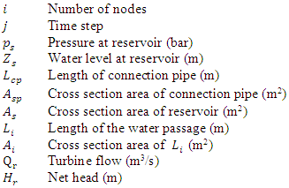
References
| [1] | R. Andrews, "Energy Matters", [Online]. Available: http://euanmearns.com/emissions-reductions-and-world-energy-demand-growth/. [Accessed 20 October 2020]. |
| [2] | Xhevat Berisha, Bukurije Hoxha, Drilon Meha, "EFFICIENCY ANALYSES FOR SMALL HYDRO POWER PLANT", International Journal of Modern Trends in Engineering and Research (IJMTER), vol. 4, p. 156, 2017. |
| [3] | Storli, Pål-Tore Selbo; Lundstrøm, T. Staffan, "A New Technical Concept for Water Management and Possible Uses in Future Water Systems", Multidisciplinary Digital Publishing Institute (MDPI), vol. 11, p. 2, 2019. |
| [4] | Marte Mestvedthagen; Pål-Tore Storli, "Increasing Operational Flexibility of Hydropower by New Technology", Norwegian University of Science and Technology (NTNU), p. 30, 2019. |
| [5] | Kumar, A.; Schei, T.; Ahenkorah, A.; Rodriguez, R.C.; Devernay, J.-M.; Freitas, M.; Hall, D.; Killingtveit, "IPCC Special Report on Renewable Energy Sources and Climate Change Mitigation", [Online]. Available: https://www.ipcc.ch/site/assets/uploads/2018/03/Chapter-5-Hydropower-1.pdf. [Accessed 25 October 2019]. |
| [6] | Naki´cenovi´c, N.; Alcamo, J.; Davis, G.; de Vries, B.; Fenhann, J.; Gaffin, S.; Gregory, K.; Griibler, A., "Special Report on Emissions Scenarios: A Special Report of Working Group III", [Online]. Available: https://www.ipcc.ch/site/assets/uploads/2018/03/emissions_scenarios-1.pdf. [Accessed 25 October 2019]. |
| [7] | I. E. A. (IEA), "World Energy Investment 2018", [Online]. Available: https://www.iea.org/wei2018/. [Accessed 25 October 2019]. |
| [8] | K. Trenberth, "The Effects of Temporary State Aid Rules Adopted in the Context of the Financial and Economic Crisis", European Commission, vol. 47, p. 123-138, 2011. |
| [9] | Cengel, Y.A.; Cimbala, J.M, "Fluid Mechanics, Fundamentals and Applications", Book, McGraw Hill Education, no. New York, NY, USA, 2014 ISBN 987-1-259-01122-1. |
| [10] | Juárez, A.; Adeva-Bustos, A.; Alfredsen, K.; Dønnum, B.O, "Performance of A Two-Dimensional Hydraulic Model for the Evaluation of Stranding Areas and Characterization of Rapid Fluctuations in Hydropeaking Rivers", Norwegian University of Science and Technology (NTNU), vol. 11, p. 201, 2019. |
| [11] | M. H. Chaudhry, "Applied Hydraulic Transients, New York", Book, Springer New, 2014. |
| [12] | E. Commission, "The Effects of Temporary State Aid Rules Adopted in the Context of the Financial", [Online]. Available: https://ec.europa.eu/competition/publications/reports/temporary_stateaid_rules_en.html. [Accessed 25 October 2019]. |
| [13] | A. C. E. E. S, "Energy Storage", [Online]. Avalable: https://web.archive.org/web/20130206134815. [Accessed 25 October 2019]. |
| [14] | T. Moen, "Mitigation of Discharge Fluctuations from Hydropower Plants by Active Measures", Master’s Thesis, Norwegian University of Science and Technology, Trondheim, Norway, June 2018. |
| [15] | Hydro Flex, "Social acceptance and mitigation of environmental impact", [Online]. Available: https://www.h2020hydroflex.eu. [Accessed 11 March 2019]. |
| [16] | S. J Saltveit et al, "Field Experiments on Stranding in Juvenile Atlantic Salmon (SalmoSalar) and Bown Trout (salmon Trutta) During Rapid Flow decreases caused by Hydropeaking", Regulated Rivers (Research & Management), vol. 2, p. 8, 2001. |
| [17] | Roser Casas-Mulet, Svein Jakob Saltveit, and Knut Tore Alfredsen, "Hydrological and thermal effects of hydropeaking on early life stages of salmonids: A modelling approach for implementing mitigation strategies", Science of the Total Environment (STE), vol. 4, p. 10, 2016. |

 Abstract
 Reference
 Full-Text PDF
 Full-text HTML