J. G. Egbe1, J. C. Agunwamba2
1Civil Engineering Department, Cross River University of Technology, Calabar, Cross River State, Nigeria
2Civil Engineering Department, University of Nigeria Nsukka, Enugu State, Nigeria
Correspondence to: J. G. Egbe, Civil Engineering Department, Cross River University of Technology, Calabar, Cross River State, Nigeria.
| Email: |  |
Copyright © 2020 The Author(s). Published by Scientific & Academic Publishing.
This work is licensed under the Creative Commons Attribution International License (CC BY).
http://creativecommons.org/licenses/by/4.0/

Abstract
Water driven bounces are among the most perplexing marvels that happen in nature under an assortment of conditions and have stood out for quite a long time. The present paper deals with the development of the mathematical and proposed design of mathematical derivations for open flow channel, the laboratory aspect is not presented in this paper. Hydraulic jumps constitute a common phenomenon in the hydraulics of open channels that increases the shear stress on streambeds and promoting their erosion, is a limited wonder that happens in prismatic open channels. To determine the required channel protection, to predict the height, length, location of the occurrence of potential hydraulic jump has remained a subject of much research in literature, this has posed several challenges to many practicing engineers. Yet there are many disparities between experimental and predicted results. Perhaps the model results have not been very satisfactory because of the negligence of some important factors such as bed friction effects, shear, and other factors in the modeling efforts. Location is required to enable the design of hydraulic structures with an adequate depth to avoid the spilling over of water in the channel. The length of a hydraulic jump is typically obtained from empirical functions of the jump height, based solely upon experimentation. This study seeks to help develop mathematical equations and procedures for the proposed design and safe operation of open channel flow as shown in Figures 7 and 8. Determination of the jump location in a channel requires the jump equation along with the gradually-varied flow calculations, in this paper, the conditions governing the formation, as well as the hydrodynamic characteristics of the hydraulic jumps, were considered for a wide range of flows and different boundary conditions.
Keywords:
Channel, Development, Hydraulic Jump, Turbulence, Streambed
Cite this paper: J. G. Egbe, J. C. Agunwamba, The Proposed Design and Derivation of Mathematical Procedure for Modeling of Hydraulic Jump in a Broad Crested Weir in an Open Channel Flow, International Journal of Hydraulic Engineering, Vol. 9 No. 1, 2020, pp. 9-14. doi: 10.5923/j.ijhe.20200901.02.
1. Introduction
A pressure-driven hop (hydraulic jump} is an open divert marvel that progress from supercritical to sub-basic stream happens. It grows huge scope disturbance, surface waves, and shower. Further, it disseminates vitality and guarantees the entrainment of air into water. Hop is generally made in the area where the self-air circulation of the stream is required to improve the broke up oxygen substance of water/wastewater in the treatment procedure. In open channels, the change from a fast, supercritical stream to a moderate, subcritical stream is named a water-driven bounce or hydraulic jump. The progress happens out of nowhere and it's portrayed by an abrupt ascent of the free surface, with solid vitality dissemination and blending, enormous scope choppiness, air entrainment, waves, and splash. The open channel includes flows occurring in channels ranging from rivulets, flowing across a field to a draining system or gutters along residential streets and highways to partially filled sewers carrying wastewater to irrigation channels, rivers, canals, and lakes. The free surface is essentially an interface between two fluids of different density and in the case of the atmosphere, the density of air is much lower than the density of water and besides, the pressure is constant. Natural channels, like rivers and creeks, resulting from the geophysical processes acting at the earth's surface, without essential participation of human activity as shown in Figures 1 and 2 respectively.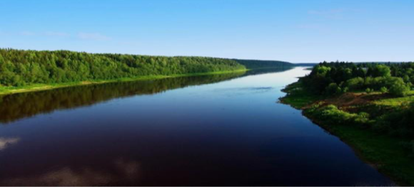 | Figure 1. Natural open channel flow |
 | Figure 2. Artificial open channel flow |
The natural stream corridors, as depicted in Figure 3, usually contain an essentially non-vegetated bank-full channel that may flow ephemerally within adjacent vegetated benches or over banks and higher outer banks. The spilling of flows out of the bank-full channel onto wider floodplain terraces provides important interaction between water, soil, and vegetation. As floodwaters spread out onto the floodplain terraces, energy is dissipated, riparian vegetation receives water, and sediment can be conveyed through the system.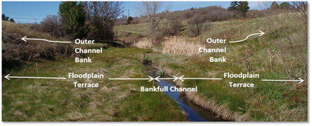 | Figure 3. Natural channel cross-section illustrating floodplain terraces |
Similarly, the natural stream channels are dynamic and change over time in response to watershed conditions, hydrology, and other factors. Nevertheless, large floods can result in rapid channel evolution/avulsion. When the floodplain is preserved, these natural changes have space to occur with lower potential for damage than channels that are constrained as depicted in Figure 4.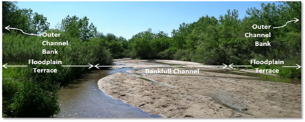 | Figure 4. Sand-bed stream in open channel flow |
Contrarily, artificial channels are constructed by men and made up of among others, navigable energetic and irrigation channels. Open channel is divided into two namely prismatic and non-prismatic channels. A prismatic channel features a constant cross-sectional shape and constant longitudinal bottom slope and in fact, such properties are often possessed only by artificial channels. All-natural channels are non-prismatic and in natural channels, the section is often either compacted or composite as presented in Figure 1. In composite channels, they exist a cross-section of distinct parts that are characterized by different bed elevations and possibly different bed roughness, the main work on jump formation has been, historically, directed towards the massive engineering excavated channels with near horizontal bed slopes and straight-sided cross-sectional shapes. Both experimental and analytical treatments find wide application in such an open channel design. Figure 5 depicts the kinds of hydraulic jumps.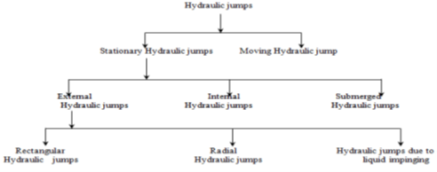 | Figure 5. Types of a hydraulic jump in open channel |
The bounce stature, notwithstanding, might be anticipated precisely utilizing force hypothesis alone [1], [2], [3]. Normally, the release and upstream profundity are as of now known, and what stays to be resolved is the downstream "sequent profundity". This holds for water-powered hops in shut channels, although for this situation, a jump in water surface can fill the channel, creating pressure stream conditions downstream and keeping the surface from arriving at the normal sequent depth. In 1818, Bidone [4] was credited as the main researcher that portrays the hydraulic jump in a little rectangular flume. The first work done on the water driven hop was accepted to have been performed by Bidone in 1820 and included as a component of his diaries [5]. The work done by Bidone just as the work is finished by Belanger in building up the sequent profundity condition is not laid out in any of the accessible writing regarding this matter. Essentially, [6] led additional work on the connection between the liquid energy and pressure-driven bounce. Critically, the arrangement of dimensionless examinations for the water-powered bounce was completed by the U.S.R Bureau of Reclamation in 1954 and in this way, detailed by [7]. Moreover, [8] did an investigation on level components through which this fundamental information on the hydraulic jump was gained. All the more along these lines, in 1932, Perterka [9] grouped the bounce or jumps in their distributed work into four classes as indicated by the estimation of the entering number. Kindsvater [10] in his work discussed the impacts of the inclining channel would have on the water-powered hop. Similarly, [11], [12], [13] made a broad exploration of hydraulic jumps in open channels respectively. As needs are, [14] they assessed to think about the attributes of various sorts of bounces. Recently, Ewah [15] studied experimental investigation of energy dissipation in hydraulic jump and a comparison of weir and level bedded constricted flume as well as the work done by Egbe [16] on the correlation between critical overflow, depth ratio, and Froude number in broad-crested weir.
2. Development of a Mathematical Procedure
The flow in the open channel over the height of a weir and the cross-section of flow will increase from y1 to y2, and its velocity decreases. The six variables are the height of the upstream of the jump (y1), the height of the downstream after the jump (y2), the viscosity of the flow (µ), the density of the fluid  the flow rate per unit width of the channel (q) also we expect the constant acceleration due to gravity (g) to be important since the gravitational force will be greater on the larger column of water after the jump than on the smaller column upstream of it. Thus, we have five variables of interest and the relationship will be written as:
 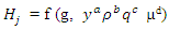 | (1) |
To carry out the dimensional analysis, will write out the dimensions of each variable:
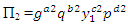
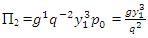
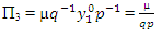
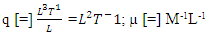 For the repeating variables, we can choose any three variables and write out their dimensionless terms as follows:
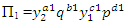 | (2) |
 | (3) |
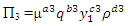 | (4) |
The dimensional analysis of the above equations will yields: | (5) |
 | (6) |
 | (7) |
For the above dimensional equalities will require three equations to satisfied, viz: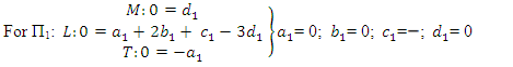 | (8) |
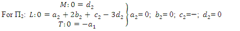 | (9) |
 | (10) |
The solution of the above-derived equations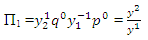 | (11) |
 | (12) |
 | (13) |
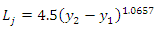
The proposed equation to calculate the location of the length of the jump in the open channel is shown in Figure 1. Nevertheless, all the empirical equations are formulated under certain limits of operation. The limits of the operation of the proposed equation are presented as follows: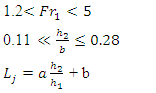 | (14) |
 | (15) |
 | (16) |
The above Equation 16 is the developed mathematical equation that can be used in conjunction with experiments in the laboratory to predict the dimensions or location of the hydraulic jump in the open channel flow, as presented in Figure 6. Where a, b, c, and d, are constants that can be found by regression analysis  upstream and downstream water depths of hydraulic jump respectively. The variable
  is the ratio of water depth in subcritical flow conditions downstream of the hydraulic jump and water depth in the supercritical condition in upstream of the hydraulic jump.
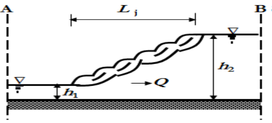 | Figure 6. Location of a hydraulic jump in the channel |
2.1. The Proposed Design for the Mathematical Development
 | Figure 7. The Proposed Experimental Design of Test section of the channel |
 | Figure 8. The Proposed design of specific energy and curves of the constricted flume |
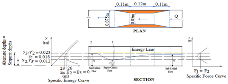
 | Figure 9. The design of the flow over a Broad-Crested Weir |
3. Derivations for the Specific Energy
In a simpler case, we consider two possible states of specific energy in a rectangular channel of width B. The discharge per unit width for this channel is given by,  | (17) |
Equation. (17), can now be written as | (18) |
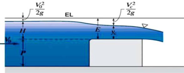
For a given channel of constant width, the value of q remains constant along the channel although the depth y may vary. The variation y is plotted in a specific energy diagram. When plotted the curve, will show that the specific energy will attain a minimum value at a certain depth for a given flow condition. This depth is known as critical depth and it can be obtained by setting  in Equation. (18).Minimum specific energy occurs at,
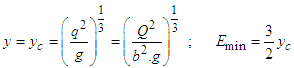 | (19) |
The velocity of flow at “critical depth” is known as “critical velocity”  and the corresponding discharge is
 , and when
  , no solution exists and thus the flow is unrealistic. For
  , there are two possible solutions; 1. Large depth with
  Is sub-critical flow.2. Small depth with
  is called super-critical flow.
4. Derivations for the Flow over the Weir
The open channel flow over a weir as shown in Figure 9. The behaviour of the free surface is sharply different based on the approach of the flow; i.e. sub-critical or super-critical. For frictionless two-dimensional flow, sections ‘1’ and ‘2’ are related by continuity and momentum equation;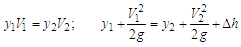 Eliminating
  between the above cubic polynomial equations for water depth
  over the bump:
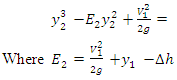 | (20) |
The following points were noted down from the above analysis; 1. Equation (20) has one negative and two positive solutions if it is not too large. Its behaviour is shown in Figure 9 and depends upon whether the point ‘1’ is on the upper or lower leg of the energy curve. 2. In the sub-critical approach, the water level will decrease at the bump whereas, in super-critical approach flows, the water level will increase over the bump. 3. If the bump height reaches, the flow at the crest will be critical. In this case, no physical solution is possible i.e. too large a bump will ‘choke’ the channel and cause a frictional effect, called “hydraulic jump”.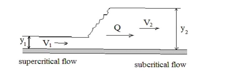 | Figure 10. Hydraulic Jump with Upstream and Downstream Sections |
 | (21) |
Where  is the channel width of the broad crested? The pressure force at either side is hydrostatic and acts at the channel cross-sections i.e.
 | (21) |
Using Equation. (23), in Equation (21), we get, | (22) |
Similarly, the mass and energy conservation equations can be written for section ‘1’ and ‘2’ respectively i.e.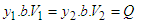 | (23) |
 | (24) |
The head loss  is due to violent turbulent mixing and dissipation that occurs within the jump itself. All Equations, (21 to 23), are satisfied
  and
and  . It represents a trivial case when there is no jump. The other possible solution can be obtained by combining Equations. (23, and 24) to eliminate
  i.e.
i.e.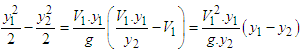 | (25) |
Simplification of this equation gives,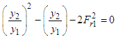 | (26) |
Where  is the upstream Froude number? The possible solution for Equation. (26), is
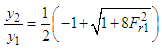 | (27) |
The dimensionless head loss  can then be obtained from Equation. (27), as,
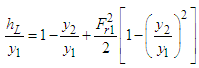 | (28) |
For a given value  , the depth ratios
  are obtained from Equation (28) and then the head loss
  is calculated from Equation (27). It will be negative if
  (since the negative head loss violates the second law of thermodynamics). The flow must be super-critical
  to produce the discontinuity called “hydraulic jump” and there is a considerable energy loss across the hydraulic jump. This is extremely useful in many situations; e.g. the relatively large amount of energy contained in the fluid flowing down the spillway of a dam causes damage to the channel below the dam. By placing suitable flow control objects in the channel downstream spillway, it is possible to produce hydraulic jump on the apron of the spillway and thereby dissipate a considerable portion of the energy of the flow i.e. the dam spillway produces super-critical flow and the channel downstream of the dam requires sub-critical flow. Hence, the hydraulic jump provides a means to change the character of the flow.
4.1. Implementation of the Design
The weirs are considered as broad- crested because the height of water above the weir crest is less than two times of the width of the crest of the weir. The distance between the weir and the jump (Dj) is taken as the distance between the weir’s tail face and the start of the wake of the jump. While the distance between the venturi-flume and the jump (DJ) is taken as that distance between the venturi-flume’s head face and the start of the wake of the jump. For the weir, the design energy loss due to hydraulic jump will range from 0.013-0.020 depending on the geometry of the channel considered in this work. The upstream of the weir, the Froude numbers range from 0.068 to 0.090 (0.068 < Fr1 < 0.09), showing that the flows will be subcritical. In the pre-hydraulic jump section, from the proposed design in Figures 7 and 8, the Froude numbers range from 3.02 to 3.56 (3.02 < Fr2 < 3.56), showing that the flows will be supercritical and the jumps obtained are oscillating ones. The Froude numbers from the post-hydraulic jump section range from 0.37 to 0.41 (0.37 < Fr3 < 0.41), also showing that the flows are subcritical. The Froude numbers from the post-hydraulic jump section range from 0.37 to 0.41 (0.37 < Fr3 < 0.41). Upstream of a level-bedded constricted flume, the Froude numbers range from 0.038 to 0.052 (0.038 < Fr1 < 0.52), showing that the flows were subcritical. At the pre-hydraulic jump section, the Froude numbers range from 1.59 to 1.93 (1.59 < Fr2 < 1.93), showing that the flows were supercritical and the jumps obtained were weak ones. The Froude numbers from the post-hydraulic jump section range from 0.56 to 0.68 (0.56 < Fr3 < 0.68), also showing that the flows are subcritical.
5. Conclusions
In this study, the conditions governing the formation, as well as the hydrodynamic characteristics of the hydraulic jumps, were considered for a wide range of flows and different boundary conditions. This research seeks to help develop mathematical derivations for the design and safe operation of open channel flow as shown in Figures 7 and 8. The hydraulic jump from the proposed broad crested weir design will dissipate more energy than that caused by a level bedded constricted flume. Since the inflow Froude number Fr of a hydraulic jump is a function of sequent depth ratio or velocity ratio of the post and pre-hydraulic jump sections irrespective of the jump causative agent. Several factors that affect the performance of the hydraulic jump will be considered in future work. However, under various assumptions, researchers in the past have included some while leaving out others. Future research will consider as many factors as possible, perform factor analysis, and use it to prioritize the factors and then used the significant ones for modeling. Such factors include gravity, slope, shear friction, viscous force, and surface tension, and so on. Hopefully, future work will try to address the above problems. The open channel hydraulic jump is governed by the principle of momentum equations and several experimental works have been carried out in the past in an attempt to prove the hydraulic jump theory.
Notations
References
| [1] | Bakhmeteff, B. A. (1932). Hydraulics of open channels, No. 627.13 B34. |
| [2] | Bakhmeteff, B. A., & Matzke, A. E. (1936). The Hydraulic Jump in Terms of Dynamic Similarity. Trans. Amer. Soc. Civ. Engrs., 100, 630-680. |
| [3] | Bidone Giorgio, (1818). “Observations on the Height of Hydraulic Jump”, a report presented in Royal Academy of Sciences of Turin, pp 21 – 80. |
| [4] | Bidone, G. (1820). Experiences sur la propagation des remous, Memorie Della Reale Academia de/le. |
| [5] | Bresse JA (1860). Cours de me ´canique Applique ´e Professe ´ an ` l’Ecole des Ponts et Chausse ´es (Course in applied mechanics lectured at the Pont-et-Chausse ´es Engineering School). Mallet-Bachelier, Paris, France. |
| [6] | Chow, V. T. (1959). Open- Channel Hydraulics. New York: McGraw-Hill. |
| [7] | Chow V.T. (1973). Open Channel Flows, Mc Graw- Hill, pp. 1-60. |
| [8] | Chu, V. H., Baddour, R.E., (1970), Surges, waves and mixing in two-layer density stratified flow, Proc. 17th Congr. Intl. Assn. Hydraul. Res., Vol.1, 303-310. |
| [9] | Jalil, S. A., Sarhan, S. A., & Yaseen, M. S. (2015). Hydraulic Jump Properties Downstream a Sluice Gate with Prismatic Sill. Research Journal of Applied Sciences, Engineering, and Technology, 11(4), 447-453. |
| [10] | Kindsvater, C.E. (1944). The hydraulic jump in sloping channels. Trans. ASCE, 109, 1107–1154. |
| [11] | Peterka, A. J. (1964). Hydraulic design of stilling basins and energy dissipators. US Government Printing Office. |
| [12] | Rouse, H., Siao, T.T., Nagaratnam, S. (1959). "Turbulence Characteristics of the Hydraulic Jump." Transactions. ASCE, 124, 926-950. |
| [13] | Sturm, T. W. (2001). Open Channel Hydraulics. McGraw-Hill, New York. |
| [14] | E. G. Ewah, E. E. Nyah, R. E. E. Antigha, and J. G. Egbe. Experimental Investigation of Energy Dissipation in Hydraulic Jump: A Comparison of Weir and Level Bedded Constricted Flume. International Journal of Engineering Trends and Technology (IJETT) – Volume 61 Number 1 – July 2018. |
| [15] | J. G. Egbe; E. E. Nyah; S. E. Ubi; O. O. Ewa; E. E. Okon. Correlation between critical overflow, depth ratio, and Froude number in broad-crested weir. Asian Academic Research Journal of Multidisciplinary-Volume 5 Issue 7 pg 1-9, 2018. |
| [16] | E. E. Nyah; E. G. Ewah; S. E. Ubi; J. G. Egbe; O. O. Ewa. Experimental investigation of critical flow and energy dissipation in broad crested weir Asian Academic Research Journal of Multidisciplinary-Volume 5 Issue 7 pg 10-16, 2018. |

 Abstract
 Reference
 Full-Text PDF
 Full-text HTML