Don May1, James Allen2, Danielle Nelson1
1Department of Physics and Engineering, Fort Lewis College, Durango, CO, USA
2T-O Engineers, 280 W Prairie Ave, Suite 3, Coeur d'Alene, Idaho, USA
Correspondence to: Don May, Department of Physics and Engineering, Fort Lewis College, Durango, CO, USA.
| Email: |  |
Copyright © 2018 The Author(s). Published by Scientific & Academic Publishing.
This work is licensed under the Creative Commons Attribution International License (CC BY).
http://creativecommons.org/licenses/by/4.0/

Abstract
Air trapped in pipes is a serious problem resulting in reduced performance or complete blockage of flow in water systems. The minimum critical velocity needed to clear an air pocket from large diameter pipes has been studied but similar studies for small diameters is lacking. In this study, a series of laboratory tests are performed on 25 and 38 mm diameter pipes with 0°, 5°, 10°, 15°, 20° and 30° downward slopes. The relationship between critical Froude number and slope is determined for each diameter and found to be similar to those for larger diameter pipes. The critical velocity for the 38 mm pipe is found to be larger than that for the 25 mm pipe. The energy equation is used with pressure and flow measurements to estimate the head loss attributed to an air pocket. This value compared closely to the measured vertical height of the air pocket. Lastly, the velocity of an air pocket relative to the mean stream velocity is studied.
Keywords:
Air pocket, Critical velocity, Froude number, Head loss, Air pocket velocity
Cite this paper: Don May, James Allen, Danielle Nelson, Hydraulic Investigation of Air in Small Diameter Pipes, International Journal of Hydraulic Engineering, Vol. 7 No. 3, 2018, pp. 51-57. doi: 10.5923/j.ijhe.20180703.02.
1. Introduction
Air trapped in pipelines can result in a range of negative impacts including pressure surges, diminished flow or complete blockage (Lescovich 1972, Stephenson 1997). For many decades, researchers have studied this phenomenon and several thorough reviews exist (Falvey 1980, Lauchlan et al. 2005, Ramezani, Karney and Malekpour 2016).Dissolved air occurs naturally in water and is one of several sources of air entrainment in pipes. The natural air content in water varies with pressure and temperature. Lescovich (1972) points out that an air content of 2% is not unreasonable and is enough dissolved air to create a 30m air pocket in a 1600m long pipe. Wang (2010) reports, more specifically, that air content ranges from about 0.5% to 3% by volume. For example, the solubility of air in water at 1 atm and 20 C is 1.87% by volume (Wang 2010). At locations in a pipeline where pressure is low, air is released from solution. This may occur at high points in the terrain, at partially open valves or when the pressure decreases due to changes in pipe diameter (Escarameia 2007). Once air is removed from solution, it is not easily reabsorbed.Air also enters into a pipeline during initial filling, at pump inlets, drop shafts, vacuum valves, leaky valves and even through cracks in a pipe experiencing less than atmospheric pressure (Colgate 1966). In gravity fed water systems the dominant mode of air infiltration is during filling and through turbulence occurring at valves, break pressure tanks, and other devices and structures (Ramezani et al. 2016). Turbulence associated with the hydraulic jump that forms at the toe of an air pocket is another important source of entrained air as well as expelling air (Pothof and Clemens 2011; Pothof, Schuit and Clemens 2012).Air results in bubbles that move through a pipe and coalesce to form pockets. The dominant forces on a pocket are buoyancy, drag and surface tension. Motion ensues when these forces are not in equilibrium. Since the direction of the buoyant force is always vertically upward and the drag force is in the direction of the velocity vector, an air pocket can move up or down in a sloping pipe. In an upward sloping pipe, the buoyancy force and the drag force are in the same direction hence air will always move upward. In a downward sloping pipe, these forces are in opposite directions and the direction of air movement depends and the relative magnitudes of the forces (Falvey 1980, Lubbers and Clemens 2005a). If the buoyant force is larger than the drag force the air pocket will move upslope. Conversely, if the drag force is larger it will move the pocket downslope, clearing it from the pipe (Ramezani et al. 2016). When the force balance reaches an equilibrium the pocket ceases to move and becomes trapped, typically at a high point in the pipeline. (Pothof and Clemens 2010) studied the impact of surface tension on the clearing velocity in downward sloping pipes that ranged from 80mm to 500mm in diameter. When the Eötvös number was greater than 5000 the authors found that surface tension was not a critical factor in determining clearing velocity. However, it did influence head loss in the blow-back flow regime. Since the Eötvös number is the ratio of gravity to surface tension (ρwgD2/σ), larger values are associated with larger diameter pipes. They concluded that the critical velocity needed to initiate air pocket motion is independent of surface tension in pipe diameters greater than 200 mm.
1.1. Head Loss Due to Air in Pipes
Air in pipes is responsible for increased head loss, thus decreased flow capacity (Stephenson 1997). It has been proposed that the magnitude of the loss, HL, can be estimated as the vertical height of the air pocket or HL = L sin θ, where L is the length of the air pocket and θ is the pipe angle with the horizontal (Pothof and Clemens 2011, Corcos 2004). When more than one air pocket is present in a downward sloping pipe, the head loss is approximately equal to the combined height of all the pockets. Air pocket head loss can rapidly accumulate and ultimately approach the available hydraulic head, significantly reducing flow capacity of the pipe. Ramezani (2016) points out that surprisingly little research has been published on the consequences of head loss due to air pockets in water systems. Escarameia (2007), reports on the results of limited laboratory measurements on 150 mm diameter pipe where the head loss in a flow with a single air pocket was 25–35% greater than in pipes with no air. Pozos (2010) studied flow in a 76.2mm diameter pipeline with two pipe segments at different slopes in a low pressure laboratory system. Large air pockets injected into the system remained stationary at the slope break between the two pipes. Pozos found that the regime for the flow passing beneath the air pocket was similar to gradually varied flow in an open channel. He also found that the pressure in the air pocket effectively remains constant along the length of the pocket and thus the hydraulic grade line parallels the water surface. The data indicates that the additional head loss due to the presence of an air pocket corresponds to the expected head loss due to reduced cross sectional area added to the loss occurring in the hydraulic jump at the bottom of the pocket. Lubbers and Clemens (2005b) were interested in the unexplained cause of head loss in pressurized, combined sewer mains commonly used in the Netherlands. In their experimental setup with 220mm diameter pipe, they monitored the head loss as the pressure difference between two points in an inclined pipe and compared the case of flow with air to the no air case. They found that air was transported over a wide range of flow velocities but at moderate velocities, an air pocket (as compared to bubbles) was present over the entire length of the test section resulting in maximum head loss. Lubbers and Clemens further found that when the injected airflow rate was low, bubbles did not coalesce into pockets and the head loss was small. Conversely, whenever an air pocket exists, regardless of how it is formed, the head loss is larger. Their data shows that the head loss decreases as the flow velocity increase. The increased velocity breaks up the air pocket and the air is transported downstream, reducing the head loss (Lubbers and Clemens 2006). In a follow-up study Lubbers and Clemens (2007) showed that the head losses adjusted using Froude scaling were the same for 220 mm and 500 mm diameter pipes but the scaled value was larger for 110 mm pipe.
1.2. Critical Velocity
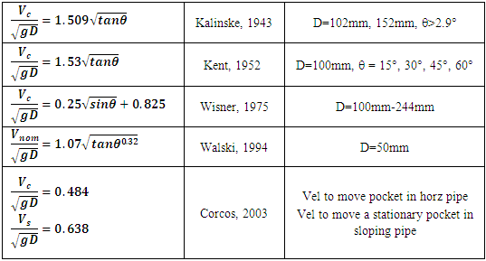
Critical velocity, Vc, is the minimum average velocity needed to expel air from a pipe through increased drag force exerted on the air pocket. As pointed out by Ramezani (2016) researchers have shown, using dimensional analysis, that Vc is a function of Froude number, Reynolds number, surface tension and pipe slope. He also notes that for larger pipe sizes viscosity and surface tension play a diminished role. Results from experimental studies, representing a variety of conditions, generally agree with this representation. In these studies, Vc is typically assumed proportional to  and θ, where g is the gravitational constant, D is the pipe diameter and θ is the pipe slope. Pressure, size of air pocket and surface tension can also play a role (Kent 1952, Falvey 1980, Walski et al. 1994, Lubbers and Clemens 2005a, Lubbers and Clemens 2006, Escarameia 2007).For reference, several critical velocity models are shown in Table 1. Lauchlan (2005) provides a detailed discussion and comparison of each of these, as well as additional models. As seen, the Froude number
  is used in these expressions; a format first used by Kent (1952) and adopted by Lauchlan (2005).
Table 1. Sample of critical velocity equations (Lauchlan et. al. 2005)
 |
| |
|
These and other critical velocity equations are shown on the same graph in Figure 1 (Lauchlan 2005).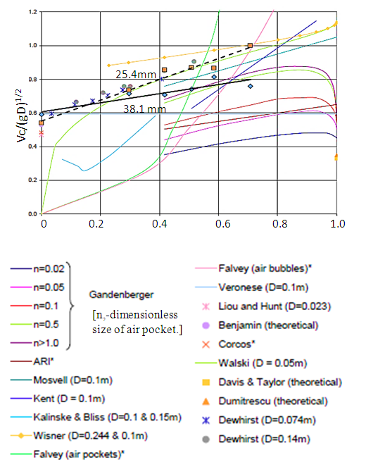 | Figure 1. Critical velocity relationships. (Reproduced from Lauchlan 2005. See this reference for details) |
Lauchlan points out that “an important conclusion of Wisner et.al. (1975) was that clearing of isolated air pockets entrapped during filling may require very high velocities for fast clearing”. Walski’s equation gives the nominal velocity, Vnom, with no air in the pipe under equilibrium conditions. These studies generally confirm the physical expectation that Vc increases with downward slope angle of the pipe but no standardized equation exists. In conclusion, there is no general agreement on the critical velocity needed to move bubbles or air pockets. Different researchers have developed different equations for Vc using a variety of pipe sizes and slopes. They generally agree that Vc increases with increasing downward slope angle up to a maximum slope and then Vc decreases to a minimum Vc at a minimum slope. For example, Gandenberger's (1957) results place the peak Vc at a slope angle of about 40° while Kalinske and Bliss (1943) report a minimum velocity at an angle of 1.2°. Some researchers found Vc to be a function of the air pocket volume while others did not include this parameter. Discrepancies in Vc are even greater for horizontal pipes. Lauchlan (2005) provides a more thorough discussion of this topic.
2. Methods
Small diameter pipe (<50mm) are prevalent in rural water supply systems in the developing world. A review of the literature confirms a dearth of studies on the flow of air in this size range of pipe, in general, and specifically on the critical velocity needed to remove air pockets. This work looks at critical velocity, head loss due to air pockets and the length and velocity of air pockets based on laboratory measurements using 25.4mm and 38.1mm pipe with slopes of 0°, 5°, 10°, 15°, 20° and 30°. Figure 2 shows the experimental setup. A constant head tank provides baseline, steady state flow and pressure conditions. The apparatus uses clear, plastic, rigid pipe in the test section and clear, flexible pipe elsewhere. Clear pipe allows us to identify and follow individual air pockets as they form and move through the system. 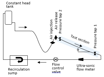 | Figure 2. Experimental setup |
Flowrate was controlled with an inline valve and measured with an ultra-sonic flow meter and a volumetric technique. The system is capable of delivering a flowrate up to 75 lpm. A combination of pressure transducers and high accuracy pressure gauges were used to measure pressure at taps 1 and 2. Experimental runs were conducted for each of the pipe diameters used in this study. The pipe slope was adjusted to a predefined angle and with the air release valve closed, air was injected into the line until an air pocket, with the target length, formed in the test section. Using the flow control valve, the flow rate was gradually increased until the air pocket was expelled. Flowrate, pressures, slope, air pocket geometry and velocity were recorded. The test sequence was repeated several times at each slope. Subsequently, the slope was adjusted to the next setting and the process was repeated.
3. Results
3.1. Critical Velocity
Using laboratory measurements the relationship between critical velocity and pipe slope was determined for both the 25.4 mm and 38.1 mm pipes (Figure 3). To be comparable with Kent and Lauchlan’s results (Figure 1), the associated critical dimensionless Froude number, 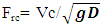 (D is inside diameter) and
  parameters are used in Figure 3. For comparison purposes, this data is also included in Figure 1, where the 38.1 mm pipe data is shown as a solid line and the 25.4 mm data a dashed line. The small pipe diameter results from this study lie within the range of data shown in Figure 1.
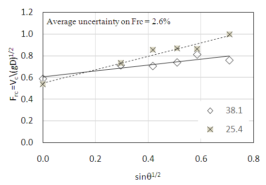 | Figure 3. Critical Froude number vs. pipe slope |
Experimental uncertainty associated with the critical Froude number measurements was determined to be approximately 2.6% of the average value, falling well within acceptable limits. Equations 1 and 2 are the associated critical velocity equations and can be compared to those shown in Table 1. Note that they use 
 | (1) |
 | (2) |
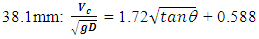
Both sets of experimental data closely follow a linear relationship with the 25.4 mm data falling slightly above the 38.1 mm data. Many of the studies shown in Figure 1 were performed with a single pipe diameter and hence the dependency of Vc on diameter cannot be determined. When diameter is removed from the analysis and Vc is used in place of the Froude number, the relationship between Vc and θ is independent of pipe diameter. This results in the 38.1 mm diameter data plotting above the 25.4 mm data (Figure 4), suggesting that a larger pipe requires a larger critical velocity.  | Figure 4. Critical velocity vs. pipe slope |
Figure 5 shows the results of measurement made in the 38.1mm pipe with air pocket lengths of 38cm, 152cm, 279cm and the same range of slopes used in the other tests. In each case the thicknesses of the pockets were approximately the same, thus the length is directly proportional to the volume and can be used as a surrogate for the volume. It is interesting to note that the critical Froude number was virtually identical for all lengths at each slope suggesting that critical Froude number is independent of pocket length. 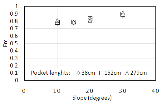 | Figure 5. Critical Froude number and air pocket length at different slopes |
3.2. Head Loss
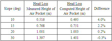
The head loss created by an air pocket is commonly assumed equal to the vertical height of the pocket. This assumption was tested using pressure measurements taken at taps 1 and 2 (Figure 2) and the flow rate in the test section. For each run, the pipe slope and length of the air pocket were also recorded. The expected loss determined from the energy equation (Eq 3) was compared to the measured height of the air pocket combined with an estimate of the friction loss computed using the Hazen-Williams method applied to the test section (Eq 4). In these equations, p is pressure, v is velocity, z is elevation, hf is the head loss due to friction, ha is the air pocket head loss, Sf is the friction slope, D and L are the inside diameter and length of the pipe, respectively and C is the Hazen-Williams coefficient. Tests were completed using 38.1 mm diameter pipe at four slopes (10°, 15°, 20°, 30°). The results are shown in Table 2. The difference between the measured height of the air pocket and the computed height (using the energy equation) was, for all cases, less than 4%.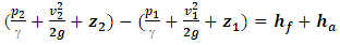 | (3) |
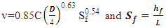 | (4) |
Table 2. Head loss due to air pocket
 |
| |
|
3.3. Velocity of Air Pockets
The velocity at which an individual air pocket travels through a pipe was studied to help develop a more comprehensive picture of the behaviour of air movement in pipes. On a practical note, it can also be used to aid in the estimation of the travel time of air through a system. Air movement was observed when bubbles coalesce to form pockets and conversely, pockets were observed to break up, forming smaller pockets and even bubbles. This formation and decomposition process is complex and no discernible pattern was identified. Because of this, the size of an air pockets can change from the time it was injected into the system to when it begins to move downstream. While precise measurements of air pocket velocity are difficult, reasonable results were obtained by timing the pocket movement over a fixed distance. If the pocket broke up, the largest segment was subsequently followed. This process was repeated several times at each pipe slope and results were averaged. As seen in Figure 6, the ratio of air pocket velocity, Vp, to the associated critical velocity, Vc, decreases with increasing downward pipe slope. 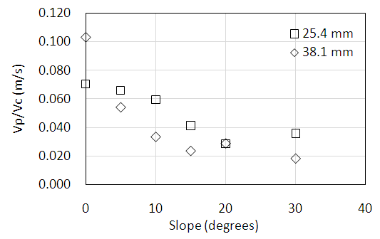 | Figure 6. The air pocket speed to critical velocity ratio with slope |
The forces acting on an air pocket are shown in Figure 7. D is the drag force the moving water exerts on the pocket and W is the weight component along the axis of the pipe. For a few cases, the pressure in an air pocket was measured and found to be constant along the pocket length confirming Pozo’s finding (2010). Since the pockets were in equilibrium, the pressure forces in the water on the upstream and downstream ends of the pocket must also be equal and contribute no net force. Consequently, D and W are the only driving forces in the direction of motion. The weight of air is much less than that of water and contributes little to the motion of the air pocket. The component of the buoyancy force, B, and friction, F, resist motion. As θ increases the component of the buoyant force opposing motion increases, resulting in a lower air pocket velocity. This force-balance argument supports the Vp/Vc trend seen in figure 6. 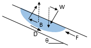 | Figure 7. Forces acting on an air pocket |
Air pockets were found to move much slower than the water. The air pocket velocity ranged from about 3% to 10% of the critical velocity (mean flow velocity in the pipe). When plotted on the same graph (Figure 8) this difference in magnitude is easily seen. It is also interesting to note that while the critical velocity increases with increasing pipe slope, the air pocket velocity decreases. 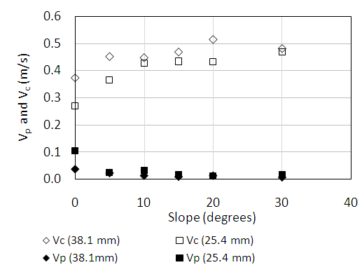 | Figure 8. Comparison of critical (vc) and air pocket (vp) velocities |
4. Discussion
The impetus for this work is partially based on experiences the authors have had with small, rural, gravity fed water system in Nicaragua. Nearly exclusively, these system use pipe diameters of 50 mm or less. In the mountainous regions in the northern part of the country, conduction lines are especially susceptible to air problems. Due to undulating terrain, it is not uncommon to find 10 or more trapped air pockets in one kilometer of pipe, especially during filling of the system. Careful design and construction of the pipeline alignment to avoid following the undulations of the natural landscape will help minimize trapped air, but is time and labor intensive. Installing air release valves can also be used to remove air from a pipeline. If possible, designing the pipeline to achieve the critical velocity needed to hydraulically move air pockets through the system is a direct and effective remediation approach. The goal of this work was to investigate the hydraulic behaviour of air in small diameter pipes by performing a series of laboratory tests on 25.4 mm and 38.1 mm diameter pipes. Specifically, critical velocity as a function of pipe slope and diameter, head loss due to an air pocket and air pocket velocity were investigated. The following is a list of relevant conclusions.1. The critical Froude number vs. slope relationships for 25.4 mm and 38.1 mm pipe falls within the general range and exhibit the same general linear trend as reported by other researchers for larger diameter pipes. As seen in Figure 1, there is no obvious or consistent pattern within the data. For example, several researchers report data on 100 mm pipe, but the results are not consistent and display large variations. The use of different experimental setups, measurement techniques and reporting conventions may contribute to this outcome. While the dimensionless critical Froude number is typically used to represent critical velocity, it does confound the effects of velocity and diameter. When critical velocity is used (Figure 4), we found that the larger diameter pipe required a larger clearing velocity. Physically, this can be explained if it is assumed that the larger pipe would have a larger volume air pocket, even if the length was held constant. In this case, the buoyant force in the larger diameter pipe would be greater than that in the smaller pipe, requiring a larger inertial drag force, thus velocity, to move the pocket.2. Tests in the 38.1 mm diameter pipe with air pocket lengths of 38cm, 152cm and 279cm show that the critical Froude number did not vary with pocket length (Figure 5). At first consideration, this result is somewhat surprising since a larger air pocket volume would be associated with a larger buoyant force and thus require a larger inertial drag force to move the pocket. One possible explanation, corroborated by observations, is that frequently, at critical velocity, an air pocket would not necessarily move through the system intact but would progressively be broken into separate pieces which would then move downstream. This process would repeat until the entire pocket was removed, frequently over a short time period. 3. In other studies, no indication of the relationship between pipe diameter and critical velocity is given. The results of this study (based on two diameters) suggests that the larger diameter pipe requires a larger clearing velocity (Figure 4). This result needs further corroboration over a wider range of diameters. Certainly, as the diameter decreases surface tension (not considered here) will play an increasingly important role and ultimately will control.4. Arguably, head loss due to air in pipes has a very significant impact on the hydraulic integrity of a system. As air accumulates, this head loss erodes the energy available for driving flow, resulting in poor performance or complete blockage. Laboratory measurements confirmed the general assumption that air pocket head loss can be approximated as the vertical height of the pocket. Based on repeated measurements at 4 different pipe slopes, the average difference between the computed and measured head loss, modelled as the height of the air pocket, was less than or equal to 4%. In two of the cases the difference was less than 0.5%. This is important experimental confirmation of a long assumed premise.5. The velocity of an air pocket moving downstream, in the direction of flow, was found to be less than 10% of the mean flow velocity. The pocket is primarily driven by the inertial drag force and resisted by buoyancy and friction. The pocket velocity decreases with increasing pipe slope due the influence of the increasing buoyance force. While there is a measurable difference between the critical velocity for a 25.4mm and 38.1mm diameter pipe, the speed of an air pocket was found to be independent of diameter. 6. Installation of automatic air release valves at critical points in a pipeline is a common, and frequently effective, method for removing air from a system. The downsides to installing air release valves are that they complicate the system, require periodic maintenance and increase the both the initial and ongoing operational cost, which, for a developing community, can be significant. Another problem is that these valves are frequently not available, even in large cities, let alone rural areas. As a follow-up to this study we have designed an automatic air release valve that can be constructed from standard PVC pipe and associated parts that can be purchased from any hardware store and assembled with a few common tools.
ACKNOWLEDGEMENTS
This work was partially completed as part of a senior engineering design project. Funding was provided by Fort Lewis College.
References
| [1] | Colgate, D., (1966). “Hydraulic model studies of the flow characteristics and air entrainment in the check towers of the main aqueduct, Canadian river project Texas.” Rep. No. Hyd-555, U.S. Dept. of the Bureau of Reclamation, Denver. |
| [2] | Corcos, G. (2004). Air in Water Pipes, A manual for designers of spring-supplied gravity-driven drinking water rural delivery systems. Agua Para La Vida, Berkeley, CA 94705, USA. |
| [3] | Escarameia, M. (2007). Investigating hydraulic removal of air from water pipelines. In Proceedings of the Institution of Civil Engineers-Water Management, 25-34. Thomas Telford Ltd. |
| [4] | Falvey, H. T., (1980). Air-water flow in hydraulic structures. NASA STI/Recon Technical Report N, 81. |
| [5] | Gandenberger, W., (1957). Design of overland water supply pipelines for economy and operational reliability (rough translation from German by W.A. Mechler, discussion of "Factors influencing flow in large conduits." Report of the task force on flow in large conduits of the committee on hydraulic structures, ASCE, Vol.92, No. HY4, 1966. |
| [6] | Kalinske, A.A. and Bliss, P.H., (1943). Removal of air from pipe lines by flowing water. Proceedings of the 30th American Society of Civil Engineers (ASCE) 13(10), 3. |
| [7] | Kent, J. C. (1952). The entrainment of air in water flowing in circular conduits with downgrade slopes. Berkley, California: Doctoral thesis, University of California. |
| [8] | Lauchlan, C., M. Escarameia, R. May, R. Burrows & C. Gahan, (2005). Air in pipelines. HR Wallingford. Report SR, 649. |
| [9] | Lescovich, J. E. (1972). Locating and sizing air-release valves. Journal of American Water Works Association, 64, 457-461. |
| [10] | Lubbers, C. & F. H. L. R. Clemens, (2005a). On detecting gas pockets in pressurized wastewater mains. Proc., 10th Int. Conf. on Urban Drainage, Copenhagen, Denmark. |
| [11] | Lubbers, C. L. & F. Clemens. (2005b). Capacity reduction caused by air intake at wastewater pumping stations. In Proc. Water and Wastewater Pumping Stations Conference, April. |
| [12] | Lubbers, C. L. & F. H. L. R. Clemens (2006). Breakdown of air pockets in downwardly inclined sewerage pressure mains. Water Science and Technology, 54, 233-240. |
| [13] | Lubbers, C.L. and F.H.L.R. Clemens, (2007). Scale effects on gas transport by hydraulic jumps in inclined pipes; comparison based on head loss and breakdown rate. 6th International Conference on Multiphase Flow. Leipzig, Germany. |
| [14] | Pothof, I. & F. Clemens. (2010). On elongated air pockets in downward sloping pipes. 499-503. Journal of Hydraulic Research. |
| [15] | Pothof, I.W.M. and F.H.I.R. Clemens, (2011). Experimental study of air–water flow in downward sloping pipes. International Journal of Multiphase Flow, 37, 278-292. |
| [16] | Pothof, I., A. Schuit & F. Clemens (2012). Influence of surface tension on air-water flows. Journal of Hydraulic Engineering, 139, 44-50. |
| [17] | Pozos, O., A. Sanchez, E. A. Rodal & Y. V. Fairuzov (2010). Effects of water–air mixtures on hydraulic transients. Canadian Journal of Civil Engineering, 37, 1189-1200. |
| [18] | Ramezani, L., B. Karney & A. Malekpour (2016). Encouraging effective air management in water pipelines: A critical review. Journal of Water Resources Planning and Management, 142, 04016055. |
| [19] | Stephenson, D., (1997). Effects of air valves and pipework on water hammer pressures. Journal of Transportation Engineering, ASCE, 101-106. |
| [20] | Walski, T. M., T. S. Barnhart, J. M. Driscoll & R. M. Yencha (1994). Hydraulics of corrosive gas pockets in force mains. Water Environ. Res., 66(6), 6. |
| [21] | Wang, K.-H., N.K. Shammas, W.A. Selke & D.B. Aulenbach, (2010). Gas dissolution, release, and bubble formation in flotation systems, Handbook of Environmental Engineering, Vol 12: Fotation Technology, pp49-83. |
| [22] | Wisner, P. E., F. N. Moshen & K. N. Kouwen (1975). Removal of air from water lines by hydraulic means. ASCE, Journal of the Hydraulics Division, 101 (HY2), 14. |

 Abstract
 Reference
 Full-Text PDF
 Full-text HTML