-
Paper Information
- Paper Submission
-
Journal Information
- About This Journal
- Editorial Board
- Current Issue
- Archive
- Author Guidelines
- Contact Us
International Journal of Hydraulic Engineering
p-ISSN: 2169-9771 e-ISSN: 2169-9801
2018; 7(2): 15-21
doi:10.5923/j.ijhe.20180702.01

Determination of Critical Depth to Avoid Free Vortex at Morning Glory Spillway by Numerical Modeling
 Abstract
 Reference
 Full-Text PDF
 Full-text HTML
Hamidreza Rahimi, Erfan Razavi
Roudehen Branch, MSc Hydraulic Structure and Civil Engineering, Azad University, Tehran, Iran
Correspondence to: Hamidreza Rahimi, Roudehen Branch, MSc Hydraulic Structure and Civil Engineering, Azad University, Tehran, Iran.
| Email: |  |
Copyright © 2018 The Author(s). Published by Scientific & Academic Publishing.
This work is licensed under the Creative Commons Attribution International License (CC BY).
http://creativecommons.org/licenses/by/4.0/

One of the challenges facing the world today is the control and efficient use of water resources, which both of cases require accurate study and construction associated with it. But due to the high costs that are imposed during the study stages, design and especially execution to the government, the development trend of this important and fundamental infrastructure has been made difficult. So the initial study and finding the economic and most technical method is very important degree, so that today we live in a world that physical and non-physical models are intended as the ultimate decision maker and all the profits and losses of a thought, idea, and structure are put facing us. Morning glory spillway is one of water conveyance structures from the reservoir to downstream and is named due to its horny shape. Among the strength of morning glory spillway, is the ability to build in narrow valleys and embankment dams which usually has a spillway apart from the body. In general, morning glory spillway acts in free mode, with radial and axial velocity, so that in this mode the water flow is entered directly into the spillway, but during vortex phenomenon incidence and tangential velocity causes the flow path diversion of the direct mode and travel the longer path flow and so it makes of energy loss and the discharge capacity reduce. Therefore, one of the solutions to prevent this phenomenon is anti-vortex devices installation. In this study, from the obtained results of software outputs analysis and experimental data can be pointed out to the accuracy and validity of the model compared to its similar experimental model.
Keywords: Critical depth, Vortex, Morning glory spillway, Numerical modeling
Cite this paper: Hamidreza Rahimi, Erfan Razavi, Determination of Critical Depth to Avoid Free Vortex at Morning Glory Spillway by Numerical Modeling, International Journal of Hydraulic Engineering, Vol. 7 No. 2, 2018, pp. 15-21. doi: 10.5923/j.ijhe.20180702.01.
Article Outline
1. Introduction
- Vortices formed at different kinds of hydraulic structures, such as hydropower intakes, spillway intakes or pump sumps, may have detrimental effects on the operation of the structure. Vortices have their origin in swirling flow, which form at the hydraulic intake structure due to their location relative to surrounding boundaries and geometric properties. In simple word, a swirl is a tendency of water at the intake to move with twisting or whirling motion. The swirl motion itself in not an engineering problem. However, the degree of swirl motion is what determines the related detrimental effect and tendency of vortex formation. In trying to define vortex, one can say, a vortex is a spinning turbulent flow or fluid with closed streamline. These two terms (swirl and vortex) are interrelated, and a vortex in other word is the fluid swirling rapidly around the center. The aim of this Numerical study was to investigate the hydraulic conditions at with vortices would form in front of morning glory spillways and to determine the ways of eliminating the formation of these vortices by testing anti-vortex devices. For these reasons, a serious of experiments that had been done in experimental setup composed of a reservoir having a dimensions of 8 * 5 within no slope, Calibrated by comparing to numerical model.
2. Literature Review
- In literature, many vortices sources have been defined by researchers for different geometrical flow conditions. According to them, an eccentricity of the approach flow relative to intake structure and asymmetric approach flow caused by geometrical conditions are two most effective vortex formation triggers. Moreover, durgin & hacker (1978) defined three fundamental vortices sources (a) offset introduction, (b) velocity gradients, (c) obstruction. They emphasized that vortices are mainly initialed by: eccentric orientation of the intake relative to a symmetric approach flow, existence of shear layers of high velocity gradients, rotational wakes created by obstructions. Gordon (1970) examined 29 existing hydroelectric intakes to develop design criteria to avoid vortices at low-head intakes. At the end of this study, it was decided that the geometry of the approach flow to the intake, the velocity at the intake, the size of the intake and the critical depth are the main factors which affect formation of vortices. However, since each geometry of the intake approach channel is unique; it is hard to investigate the effect of the geometry on formation of Vortices. Therefore, it was decided to focus on other parameters which affect the vortex formation. Knauss (1987) mentioned that vortex formation causes two main hydraulic problems at intakes structures: unfavorable vibrations on the hydraulic machines and serious problems on the closed channel system due to air ingestion. As it is mentioned before, vortices are mainly triggered by eccentric orientation of the intake and asymmetric approach flow conditions due to geometry. Although hydraulic design of the intake structure is made by considering prevention of vortex formation, in some cases, the formation of vortices connot be suppressed because design requirements cannot be satisfied due to extreme approach flow conditions, submergence requirements of economic reasons. Therefore, some structural measures can be applied to eliminate vortex formation at intake structures. Rutschmann et al. (1987) proposed that air ingestion can be removed or the effect of swirl can be lowered by increasing the distance of streamlines between the intake structure and the free water surface, improving approach flow condition to remove non – uniformities, and applying some anti-vortex devices. Many different applications of anti-vortex devices in real and experimental cases are illustrated by Rutschmann et al. (Knauss, 1987).
3. Scope of Numerical Modeling
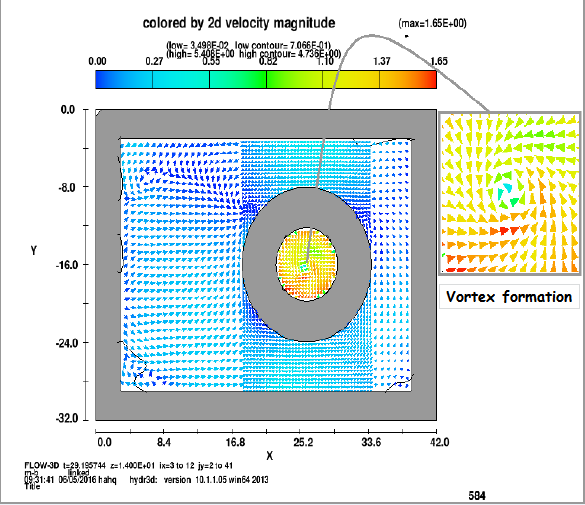
- Flow-3D is a powerful computational fluid dynamics (CFD) code, based on solving the Navier stokes Equations. Flow-3D uses finite volume approximations of the mass, momentum and energy equisions in three dimensions to analyze the complex fluid problems. It also has models for sediments transport, moving rigid bodies, flows in porous media, etc.Civil engineering flow problems often involve free-surfaces. Free-surface is handled with various ways in many computer programs. Flow-3D uses volume of fluid (VOF) technique which was first reported by Hirt et al. (1975) and by Hirt and Nichols (1981). VOF is a powerful free surface tracking method for Sharpe interfaces. VOF defines the air by boundary condition and applies in on the surface. It is not an independent flow solving algorithm.There are five main tabs the user will go from one to another while designing the applicable model. These tabs are: Navigator, Model setup, General, Physics, Fluids, Meshing and Geometry, Output, Numeric, Simulation, Analyze, Display. The aim of this numerical modeling is to investigate effects of the hydraulic parameters like velocity and head on the formation of vortices at Morning glory spillway and the use of anti-vortex devices to eliminate the formation of vortices. This was achieved by conducting experiments and comparing these experimental (Figure 1) result and data with the numerical modeling by FLOW-3D software.
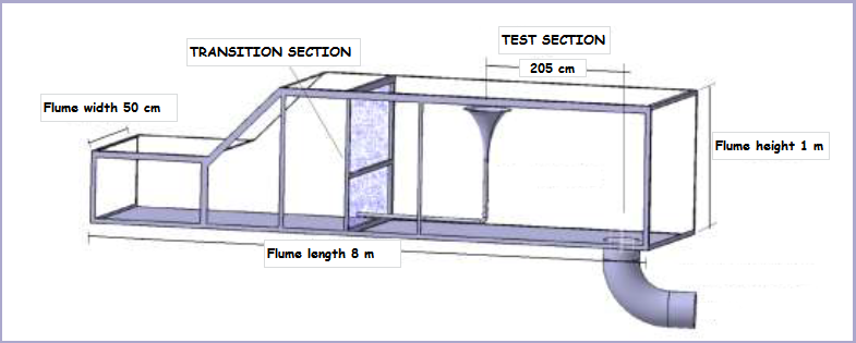 | Figure 1. Modeling elements of Azad University, Marvdasht Branch's experimental morning glory spillway |
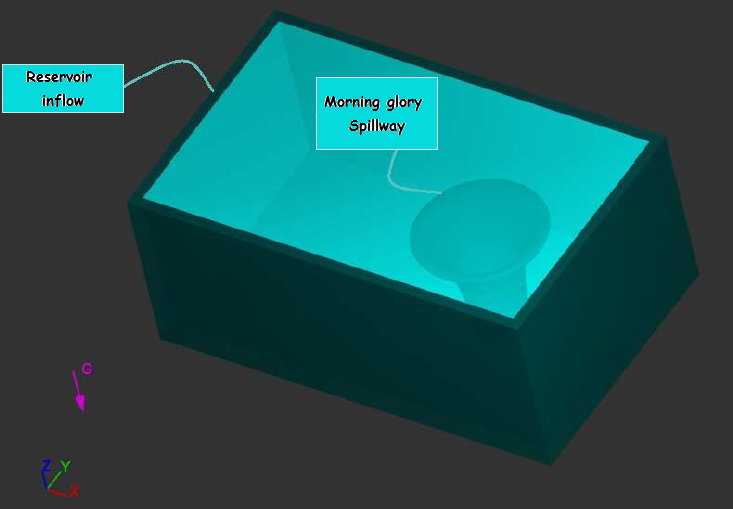 | Figure 2a. Numerical Model of Morning glory spillway Top view |
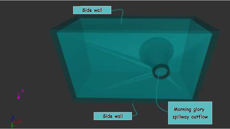 | Figure 2b. Numerical model of Morning glory spillway perspective views |
 | Figure 3a. Comparison of velocity contours for grid dependency with coarse mesh (Z-Y) |
 | Figure 3b. Comparison of velocity contours for grid dependency with coarse mesh (Y-X) |
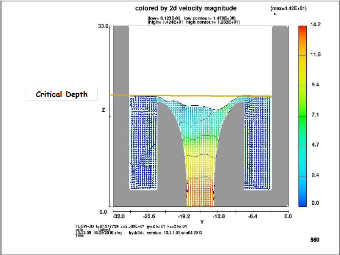
4. Results
- Experimental and numerical modeling for the critical depth required to avoid free surface vortices in both experimental and numerical modeling. It was found that the data was adequately represented when each exponent in the equation were vary for a given Reynolds and discharge. In the present manuscript effects of Reynolds, discharge And diameters of morning glory spillway entrance on the formation of vortices at morning glory spillways were investigated numerically. The available data were analyzed and equation for critical depth was derived. The results of such modeling (Figures 4a, 4b, 4c) would enable more realistic intake designs, reduce the prevalent need for model studies, and provide basic information on the primary parameters in vortex formation.
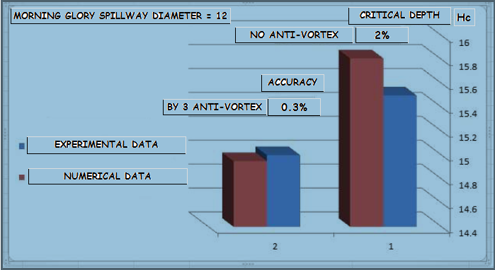 | Figure 4a. Difference between experimental data and numerical values of Hc (morning glory spillway diameter=12) |
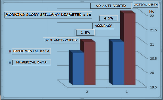 | Figure 4b. Difference between experimental data and numerical values of Hc (morning glory spillway diameter=16) |
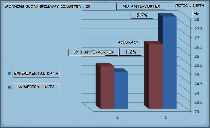 | Figure 4c. Difference between experimental data and numerical values of Hc (morning glory spillway diameter=20) |
 Whereυ is its velocity of the object relative to the fluid (m/s)μ is the dynamic viscosity of the fluid (Pa•s or N•s/m2 or kg/ (m•s))l is a characteristic linear dimension, (travelled length of the fluid; hydraulic diameter when dealing with river systems) (m) ρ is the density of the fluid (kg/m3)
5. Conclusions and Recommendations
- In the present paper the numerical model of a physical experiment is built by Flow-3D.simulation for different cases are run to investigate the hydraulic conditions at which vortices appear. The critical depth values are obtained and compare with experimental results. To enrich the numerical investigation, the effect of sidewalls distances and pipe diameter are evaluated. As well as, the effect of Reynolds number, discharge, velocity and spillway diameter on the formation of vortices at morning glory spillway were investigated numerically and comparison with experimental data. Functional equation for critical depth were derived from experimental data and numerical results as a function of relevant parameters. Vertical plates were tasted as anti-vortex devices to observe how much they are effective in reducing the strength of vortices.The conclusion of this numerical study can be listed as the following:1) The extent of the errors depend directly on the relation between the values of Hc/Di and Velocity as defined in Azad University Marvdasht branch (2013). Different velocities and Hc/Di give 2.583 percent error.2) Acceptable results are obtained for the case with anti-vortex plates. The vortex is prevented successfully in the numerical model as it is prevented in the experiment by 4 anti-vortex plates.3) Hc/Di values increase gradually and almost linearly with increasing Re number and discharge of a morning glory spillway of known diameter.4) As a function of morning glory spillway pipe diameter, there are limit values for Re and discharge above which Hc/Di is independent of velocity and function of Re and discharge.5) For all nine cases described above; yielding maximum, minimum and intermediate Hc/Di values as a function of velocity, and for all values of Re and Discharge, an functional equation were derived with quite high correlation coefficients. Equation required to determination critical depth can be written as: Hc/Di = 1.686 – 0.001 Re^0.6 + 0.114 Q^ 2.3 for future studies, the following recommendation can be made; similar tests (experimentally and numerically) should be conducted, if it is possible, the effect of change in viscous solver tasted at a wide range of Re number and Discharge.