Jaafar S. Maatooq, Emad S. Mahmoud
Building and Construction Engineering, University of Technology, Baghdad, Iraq
Correspondence to: Jaafar S. Maatooq, Building and Construction Engineering, University of Technology, Baghdad, Iraq.
| Email: |  |
Copyright © 2017 Scientific & Academic Publishing. All Rights Reserved.
This work is licensed under the Creative Commons Attribution International License (CC BY).
http://creativecommons.org/licenses/by/4.0/

Abstract
In the present study, a laboratory work has been done to measure the local scour at equilibrium state which is formed around single oblong pier fixed at the center of the section located each 30° of 180°-bend. The results show that the maximum depth of scour and the maximum extents (i.e., length and width) of scour hole and maximum Modification factor due to bend for local scour occurs when pier located at sector 90° of the bend. With increasing angle of attack for the pier in this sector the depth of scour increase linearly and the width of scour hole increased accordingly. However, an appreciable effect is also recorded with the direction of the angle of attack relative to the inner and outer bank, where the scour depth was larger with the pier skew towards the inner bank than that recorded when it skewed towards the outer bank.
Keywords:
Oblong pier, Local scour, River bend, Threshold velocity, Secondary flow, Clear water scour
Cite this paper: Jaafar S. Maatooq, Emad S. Mahmoud, Local Scour around Single Central Oblong Bridge Piers Located within 180° Bend, International Journal of Hydraulic Engineering, Vol. 6 No. 1, 2017, pp. 16-23. doi: 10.5923/j.ijhe.20170601.03.
1. Introduction
Flow pattern and the mechanism of scouring around a bridge pier have been reported by various investigators most of them focusing on pier inserted within straight reach (e.g. [2], [4], [8], [11]). However, little might interest to investigate this phenomenon when bridge pier is located within bend reach. The studies related to this context, at hand, are those conducted by; [5], [6], [7] and [13]. The sediment movement within a bend and meander reaches has been extensively studied by researchers (e.g. [9], [10] and [12]). The presence of the spiral flow and lateral sediment transport across the channel bend certainly has a direct effect on the local scour which is formed around the pier, and this effect will most likely increase with non-circular shape of the pier (e.g., oblong pier). This paper presents the experimental results of scour which is formed around one size model (3cm in width and 9cm in length) oblong shape pier inserted at centre of different sections of 180 degree channel bend at both zero and in skew angle of attack. The results are compared with those occurring when the pier immersed in straight reach channel.
2. The Experimental Setup and Procedure
Experiments were conducted in the Hydraulic laboratory of Building and Construction Engineering, UOT, Baghdad, Iraq by using the sediment races flume having a rectangular in cross section measuring 60cm width by 20cm deep. The flume comprised three sections; the 1.5m in length approach (straight reach) section, 180°-bend working section, and a 2m straight section downstream the bend connected at its end by 40cm*60cm trap basin with adjustable tailgate used to control the flow depths. The bend section has the inner and the outer radius of 37.5cm and 97.5cm respectively with arch length 3.06m. Figure 1 illustrates a plane sketch. A layer of uniform sand with 8.5 cm thickness and median diameter d50 = 0.327mm, and standard deviation σg =1.3 was placed on the bed to cover the total length of channel. The sand bed surface was levelled by a scraper. A point gauge was used to measure the water surface level and the topography of the channel bed after completion of run and complete dewatering.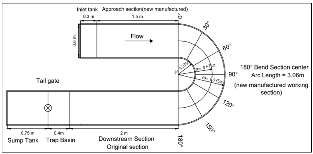 | Figure 1. Plane sketch of flume sections with necessary dimensions [1] |
[8] was defined B/L (B= width of pier and L= length of pier) should not be more than 1/3 so oblong model pier of 3 cm in width and 9 cm in length extends above water surface in height are used to simulate the pier model. This model installed at centre of flume at a desired location within bend reach (working section). The parameter θp= 0, 30, 60, 90, 120, 150 and 180 degree have been chosen to represents the sectors within the bend at which the centre of pier model have been installed for a desired run undertaken. The skew of pier was also tested to investigate the effect of different angle of attack along with the direction of skew (relative to bank) on the amount and extends of the local scour around the pier model. The skew effect was tested just when pier located at θp=90°. Figure 2 illustrates the orientation of pier when it skewed in test relative to outer and inner banks. In all experiments the same discharge equal to 218.559 l/min and the flow depth at the approach section 2.8 cm have been employed. This flow condition has adopted after conducting a wide range of trials for both the discharge and the depth of flow in order to get the flow intensity by which the clear water flow condition at the approach section is achieved. However, the sediment transporting feature occurs according to the morphological aspects along the bend reach. Many trials were also conducted to decide the suitable time at which the equilibrium of scouring process is achieved. From the trial process the flow intensity and the equilibrium time to achieve the desired requirements are V/Vc = 0.998 and Tequ.=4 hrs. respectively, where V is the flow velocity at the approach section equal to 0.21682m/s (Q= 218.559 l/min) and Vc is the velocity at threshold of bed sediment motion (critical flow velocity) at approach section equal to 0.21717m/s (it calculated according to the equation which recommended by [8]).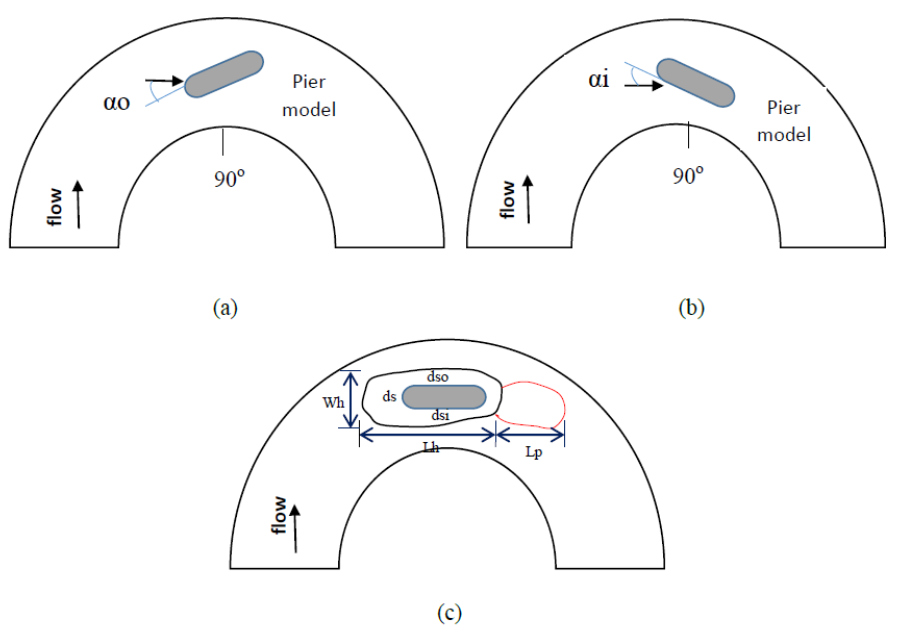 | Figure 2. Pier skew towards; (a) outer bank (b) inner bank (c) schematic symbolic of scour feature around pier |
3. Result Analysis and Discussion
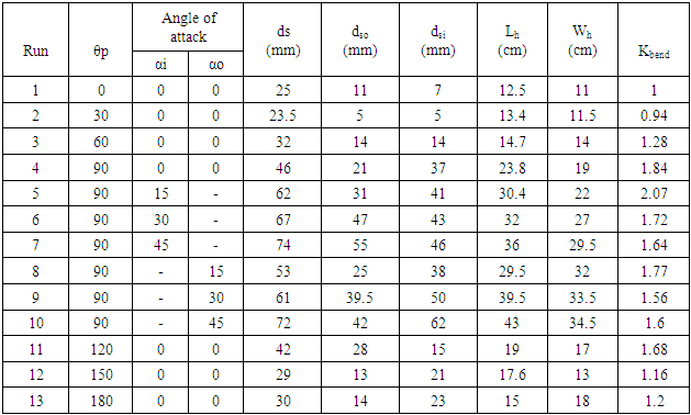
At the end of each run the measurements have been taken both longitudinally and transversely for bed form around pier model. The recorded data represent the depth of the scour and deposition relative to a plain bed of sand races before run. The modification factor due to bend (Kbend), is the main aim of this research. This factor is calculated by dividing the scour depth which is formed at nose of pier (ds) when it located at θp to the scour when the same pier model is located at the straight reach. All runs and measured parameters based on the terminology shown in Figure 2 are listed in Table 1.Table 1. Scour parameters for all experiments
 |
| |
|
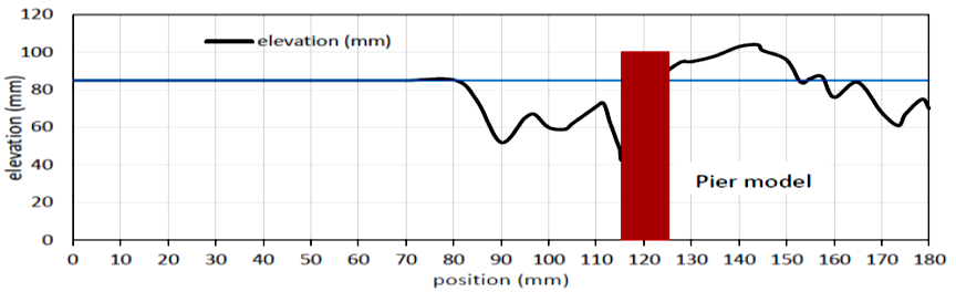
Figures 3 to 10 shows the longitudinal profiles of bed level along bend reach when pier located at a specified sector. In Figures 6 and 7 the longitudinal profiles for the three different angle of attack of pier at θp=90° are drawn to illustrate the variation in bed level due to influence the angle of attack with the outer bank and the inner bank. The transverse bed levels across the centre of pier when it installed at different position in bend are shown in Figure 11 while Figures 12 and 13 illustrate the variation of bed level transversely with three different angle of attack at θp=90°. The results listed in Table 1 shows that the maximum local scour at nose of pier ds was 46mm which is recorded when pier located at θp=90° and aligned with flow (i.e., α=0), whereas the second stage is when pier located at θp=120° where the ds=42mm. The minimum scour however, was ds=23.5mm was recorded at nose of pier when it installed with alignment of flow at θp=30°, at this location it can also note through Figure 4 that the scouring and deposition process along the centreline of bend relative to the plain bed was least as compared with those resulted when pier installed at the other locations. In the same context the highest local scour was at nose of pier when it located at θp=90°, the movement of sediment along the centreline of bend was not necessarily the largest among the other location (see Figures 3 to 10). At the sides of pier Table 1 shows that the maximum local scour which occur at the outer side was when pier located at θp=120°, while the maximum value at inner side was recorded with θp=90°, and with both cases the pier was aligned with flow.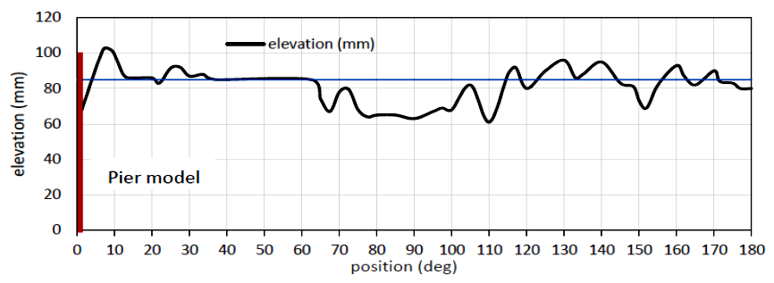 | Figure 3. Longitudinal profile along the centreline of bend reach illustrates the bed elevations at equilibrium time when pier located at θp= 0° |
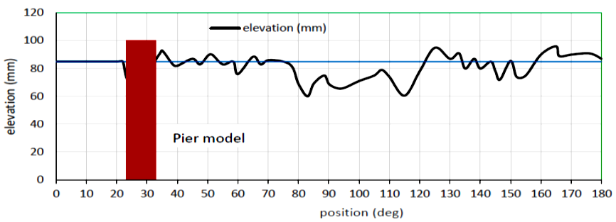 | Figure 4. Longitudinal profile along the centreline of bend reach illustrates the bed elevations at equilibrium time when pier located at θp= 30° |
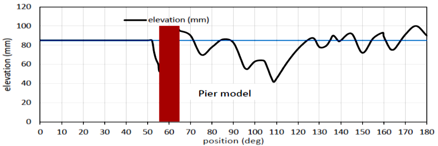 | Figure 5. Longitudinal profile along the centreline of bend reach illustrates the bed elevations at equilibrium time when pier located at θp= 60° |
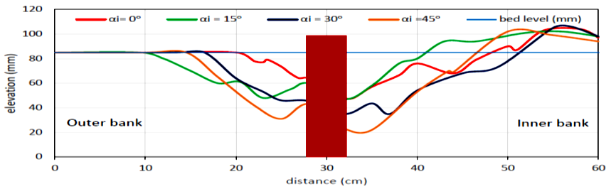
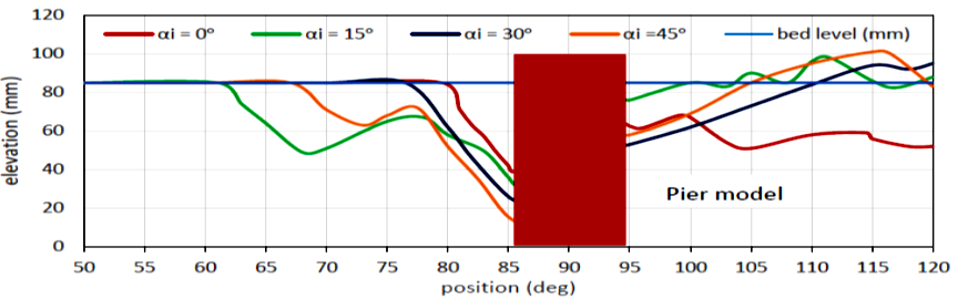 | Figure 6. Longitudinal profile of the bed elevations at equilibrium time when pier located at θp= 90° for different angle of attack with inner bank |
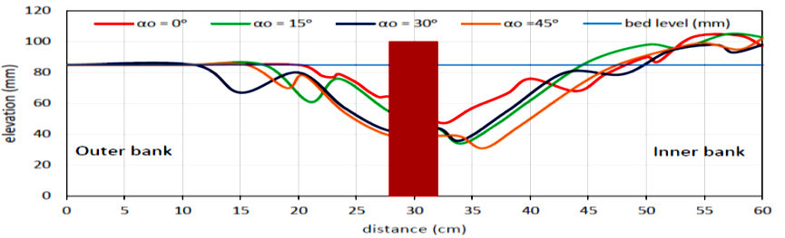
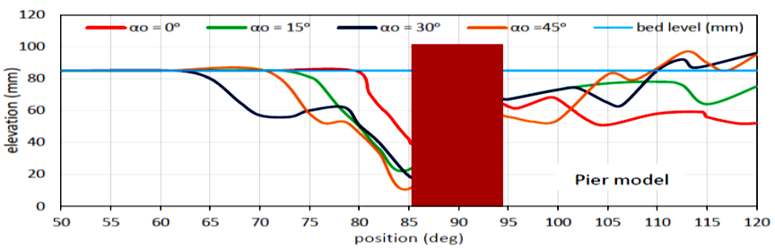 | Figure 7. Longitudinal profile of the bed elevations at equilibrium time when pier located at θp= 90° for different angle of attack with outer bank |
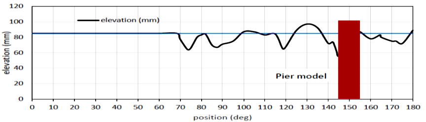
 | Figure 8. Longitudinal profile of the bed elevations at equilibrium time when pier located at θp= 120° |
 | Figure 9. Longitudinal profile of the bed elevations at equilibrium time when pier located at θp= 150° |
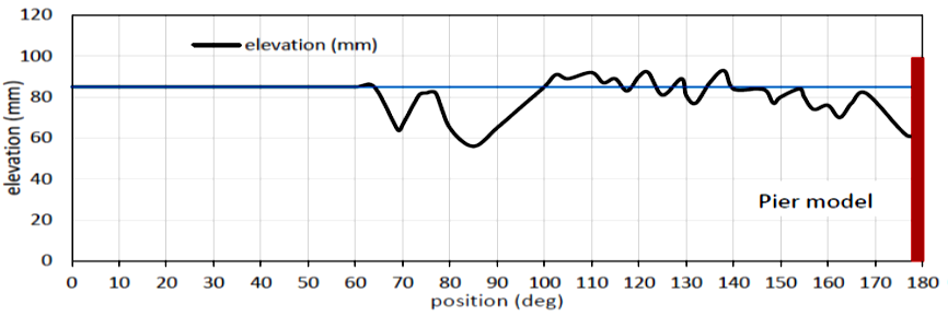 | Figure 10. Longitudinal profile of the bed elevations at equilibrium time when pier located at θp= 180° |
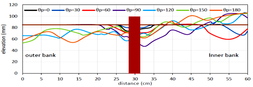 | Figure 11. Transverse bed form elevation across the centre of pier for all pier positions |
 | Figure 12. Transverse bed form elevation across the centre of pier at θp= 90° for different angle of attack with inner bank |
 | Figure 13. Transverse bed form elevation across the centre of pier at θp= 90° for different angle of attack with outer bank |
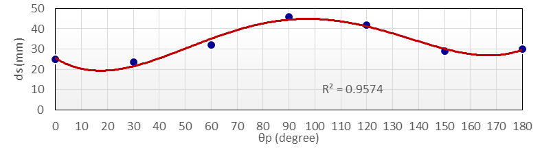
With skew action the maximum scour at outer side was recorded with αi=45° and at inner side with αo=45°. Also, when pier skewed toward the inner bank the scour at the outer side was greater compared with the results of inner side of pier. This case has become an inverse with skew toward the outer bank.Generally the local scour at nose of the pier was greater when the pier skewed towards the inner bank as compared with those recorded with skew towards the outer bank, and the largest scour was occur with the largest skew angle. The morphology of bed was taken the same context as seem through Figures 6 and 7. Finally, the experimental results show the negative action of skewed pier on local scour process that is the same criterion with skewed pier when immersed in straight reach.In present study, as mentioned previously, the aim is to find the modification factor for local scour which is formed at nose of oblong pier when it located at the centre of any section within bend. The criterion is the sector angle of pier location and the radius of bend, thus, the modification factor (Kbend) accordingly its value is not constant, Figure 14 shows the trend of this factor with sector angle and the radius of bend. The best fit formula of this factor at a determination coefficient R2=0.9574 is;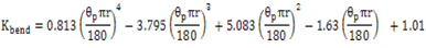 | (1) |
The variation of length Lh and width Wh of scour hole with location of pier are illustrated in Figure 15, it is evident that the length of scour hole was less when the pier located within the first one-third of bend then slightly increases up to maximum when the pier installed at θp=90°, then it begin continuously decrease within the second half of the bend, nearly the same length of scour hole was recorded with the pier when installed at θp=60° and θp=180°. In terms of width, the same trend as for length is observed however, the increase sector was less severe compared to the case of length. Also the trend lines refer that the length of scour hole is slightly greater than the width of hole when pier located within the first one-third, while the difference seems more exaggerated within the second and last third. Figure 16 shows the variations of Maximum depth of scour hole due to changes of pier location within bend reach. The trend of variations of depth of scour is same as for length and width of the scour hole. According to data points the maximum values of scour depth was recorded when pier is installed at section 90°, whereas the polynomial best fit trend line for data points refer that the maximum scour may occur practically if pier located at θp=100°. The angle of attack has also been tested to show its effect on scour amount and feature. From Figure 17 it can be deduce the increasing in angle of attack of pier lead to steadily increase in width and length of scour hole for both sides of attack. However, the length and width of scour hole for pier skewed towards the outer bank are larger than those with skew towards the inner bank.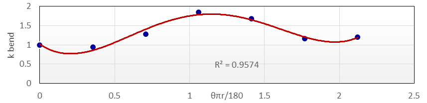 | Figure 14. Modification Factor variation with location of Pier within bend |
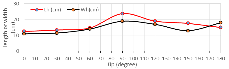 | Figure 15. Length and Width of Scour hole at different locations |
 | Figure 16. Maximum depth of scour hole at different locations |
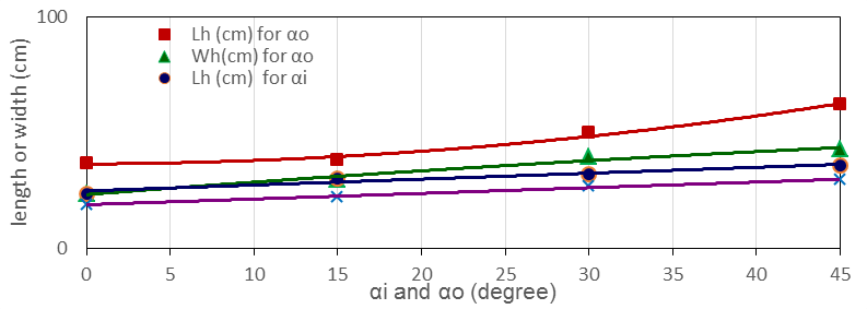 | Figure 17. Effect of angle of attack for pier with inner bank and outer bank at θp= 90° on scour feature |
4. Conclusions
This paper investigates the bend reach effects on local scour which is formed around oblong bridge piers when it installed at centre line of any sector within bend for clear water condition at the approach straight reach. After collection and analysing the experimental data the following conclusions are drawn from this experimental study. The maximum depth ds, the maximum length Lh, and the maximum width Wh of the scour hole are recorded when 3cm pier width and 9cm length installed at θp=90°. Also with the same context of straight reach the scour increases with increasing angle of attack of pier for the same flow conditions. Finally, and through the aim of this study it was provide the modification factor due to presence of pier within bend. This factor can be used as a multiplication factor with any known equations that proposed by researchers, which are basically have been derived for local scour calculation around pier located within the straight reach (e.g., [2], [8] and [11]). Through the results of present work the using of this factor become necessary to take into account the effect of bend reach on local scour process.
Notation
The following symbols are used in this paperB= width of pierds = maximum depth of scour hole at upstream face of pierdsi = maximum depth of scour hole from inner bank sidedso = maximum depth of scour hole from outer bank sided50= Mean particle size of sandKbend= Modification factor due to bend L= length of pierLh = maximum length of scour holeLp = maximum length of point bar,σg= standard deviationθp= location of the pier in the channelTequ= equilibrium time of scourV=the mean velocity at approach flowVc= the mean velocity at threshold of motion of bed sediment for approach flow Wh = maximum width of sour holeαi = angle of attack with inner bankαo = angle of attack with outer bankθp= the angle of sector at pier location
References
| [1] | AL-Ibadi, B. A. “Performance of Different Configurations of Submerged Vanes as A river Training Structure along 180° -bend” A thesis submitted to Building and Construction Department, University of Technology, Iraq, 2016. |
| [2] | Breusers H.N.C., Nicollet G., and Shen H.W. “Local Scour around Cylindrical Piers” Journal of Hydraulic Research 15:3, 211-252, 1977 (DOI: 10.1080/00221687709499645). |
| [3] | Breusers, H.N.C. and Raudkivi, A.J. “Scouring, Hydraulic Structure Design Manual” No.2, IAHR, Balkema, 143pp, 1991 (https://books.google.iq/books/about/Scouring.html?id=fDtiQgAACAAJ&redir). |
| [4] | Chiew Y. M., Melville B.W. “Local Scour around Bridge Piers”, Journal of Hydraulic Research. , Vol. 25, No. 1, pp. 15-26, 1987 (DOI.org/10.1080/00221688709499285). |
| [5] | Gamal Elsaeed, Hossam Elsersawy, Mohammad Ibraheem, Fatma Samir “Bridge Pier Scour Evaluation in Meandering Channels”, Journal of International Association of Advanced Technology and Science (JIAATS), Vol.16, No.9, pp.1-12, 2015. |
| [6] | Jueyi Sui, Daxian F., and Bryan W. Karney, 2006. “An experimental Study into Local Scour in a Channel Caused by a 90° bend”, Canadian Journal of Civil Engineering 33: (DOI: 101139/L06-037, pp.902-911). |
| [7] | Masjedi, M.S. Bejestan and H. Kazemi “Effects of Bridge Pier Position in a 180 Degree Flume Bend on Scour Hole Depth”. Journal of Applied Sciences, 10:670675, 2010 (DOI: 10.3923/jas.2010.670.675 URL: http://scialert.net/abstract/? doi=jas.2010.670.67). |
| [8] | Melville B.W., Sutherland A.J. “Design Method for Local Scour at Bridge Piers” Journal of Hydraulic Engineering, ASCE, 114:10, 1210-1226, 1988 (DOI.org/10.1061/(ASCE)0733-9429(1988)114:10(1210)). |
| [9] | Odgaard, J. and Bergs, A. “Flow Process in a Curved Alluvial Channel” Water Resources Research, Vol. 24(1), pp. 45-56, 1988 (DOI: 10.1029/WR024i001p00045). |
| [10] | Peter K. K. and John F. K. “Secondary Current and River-Meander Formation” Journal of Fluid Mechanics, Vol. 144, No. 1, pp. 217-229, 1984 (DOI.org/10.1017/S0022112084001580). |
| [11] | Richardson, E.V, and Davis, S.R. “Evaluating Scour at Bridge (4th ed.) Federal Highway Administration “Hydraulic Engineering Circular No.18”, FHWA NHI 01-001, 2001 (https://www.fhwa.dot.gov/engineering/hydraulics/pubs/hif12003.pdf). |
| [12] | Won S. and Young J. J. “Velocity Distribution of Secondary Currents in Curved Channels” Science Direct, Vol. 22, No. 5, pp. 617-622, 2010 (DOI.org/10.1016/S1001-6058(10)60003-0). |
| [13] | Yaser EMAMI, Amin S. Salamatian and Masoud GHODSIAN “Scour at Cylindrical Bridge Pier in 180 Degree Channel Bend” Fourth International Conference on Scour and Erosion, 2008 (https://izw.baw.de/publikationen/tc213/0/a_26.pdf). |

 Abstract
 Reference
 Full-Text PDF
 Full-text HTML