Paul P. Akpan, Augustine B. Ledogo
Department of Civil Engineering, Rivers State Polytechnic, Bori, Nigeria
Correspondence to: Paul P. Akpan, Department of Civil Engineering, Rivers State Polytechnic, Bori, Nigeria.
| Email: |  |
Copyright © 2015 Scientific & Academic Publishing. All Rights Reserved.
This work is licensed under the Creative Commons Attribution International License (CC BY).
http://creativecommons.org/licenses/by/4.0/

Abstract
The work is aimed at modeling the rise in water level in a flow, especially, in open channels as a result of abrupt change in flow regimes from unstable shooting flow to a relatively stable streaming flow. The cumbersomeness of manual computation of hydraulic engineering problems that involve so much iterations that led to waste of time and cost were modeled for optimal maximization of profit. The methodology involves combination with energy and momentum equations, and the mathematical model determined the engineering characteristics of the hydraulic jump. The equations of the model were simulated with visual basic programming language. A case study on the model showed that the programme runs perfectly and comparison of the results of the experiments with the manual results showed that both gave same result of 100% The results of the experiments enhanced irrigation, water supply, mix chemicals for water purification, aerate water and waste water for water treatment and removal of air bubbles in supply lines. It is recommended that the programme be used for analysis, design and consulting in engineering services.
Keywords:
Hydraulic jump, Model, Visual basic, Froude number, Critical flow, Subcritical flow, Supercritical flow
Cite this paper: Paul P. Akpan, Augustine B. Ledogo, Hydraulic Jump Model and Programming in Visual Basic, International Journal of Hydraulic Engineering, Vol. 4 No. 4, 2015, pp. 81-94. doi: 10.5923/j.ijhe.20150404.01.
1. Introduction
Hydraulic jump is the rise in water level of a flow in an open channel as a result of transition from unstable shooting flow to a more stable streaming flow due to energy loss caused by abrupt disturbance. It occurs when a supercritical flow meets a subcritical flow resulting in a flow in rapid transition with accompanying, large loss of energy due to the disturbance, (Leton, 2005). A simple example of hydraulic jump occurs when a tap is opened full and water at high pressure flows out onto a relatively near surface. The water hits the surface, jumps back in a bulge, rises up and then scatters and spread round in circle before chilling down to run away on the surface. The jumping or rising bulging scattering and spreading round is hydraulic jump. The phenomenon of hydraulic jump occurs naturally and can also be made to occur, that is, artificially. As such some practical applications of hydraulic jump include, recreational and tourist attraction, irrigation purposes, reducing uplift pressure on foundation, dissipation of excessive energy in flowing water, recovery of head loss in flume and water distribution, increase weight on dam’s apron to check uplift, increase discharge in sluice, mixing of chemicals in water treatment, aeration of water for water supply and removal of air pockets from distribution lines etc.Modeling is a process of integrating and developing scientific ideas to scale that has perfect similitude with a real situation and can be used as prototype for further development. It is the scale representation of things in the real world so that it can be copied or reproduced for full scales production of that which it represents. The product of modeling is a model, which is the scale representation of a real world situation or phenomenon which can be copied or reproduced for full scale production. Mathematical formula or design to be used to analyze the true situation of the model representation or to be copied for true life constructions a model (Ledogo 2012). A model is in effect a way of expressing a particular view of an identifiable system of some Kind. Developers build different models throughout the development process in order to verify that the eventual software system will meet the requirements (Ford, 2009, Ordon, 2012).Programming involves the process of creating a set of sequence of instructions, written with recognized codes and symbol (programming language) by a programmer to instruct the computer on what to do (Blackwell, 2002). The process includes designing, writing, testing debugging and maintaining the source code of computer program.In this work, programming the model of hydraulic jump in visual basic codes is undertaken. The main objective is to develop and programme a reliable software that can perform the job of evaluating, and calculating the resulting hydraulic jump in a flow when subjected to condition that promotes the phenomenon. The software is patentable and file format able.The scope of work includes selecting the model that can best be used to develop the programming model, determine the visual basic codes of the model parameters, perform the program listing (programming), test the programme with a case study, and discuss how to run the programme by any user.
2. Hydraulic Jump Theory
Hydraulic jumps is a phenomenon that occurs in water moving and encounters energy change (energy loss )due to change in one or more of velocity, cross section, depth etc of the water or passage channel. As such the parameters that determine flow can also determine jump characteristics. There are usually three types of flow in a moving water namely(i) Streaming or subcritical flour(ii) Normal or critical flour (iii) Shooting or super critical flourFlow is generated and sustained by energy, usually energy gradient. This energy as demonstrated in Bernoullis equation is a function of elevation, velocity and pressure (fox and Mc Donald, 1992) | (1) |
Where E = energy, y = potential energy (elevation), V = velocity of flow, g = acceleration due to gravity, ℓ = density of the waterFor hydraulic jump to occur, there should a disturbance or obstruction on the flow path. This cause the velocity to slow down abruptly and the flow transit from the shooting or super critical flow to streaming or subcritical flow. During this transition there is enormous energy loss. Hydraulic jump cannot occur when there is transition from subcritical to supercritical and it cannot occur when the transition is from supercritical to critical or from subcritical to critical flows (Leton, 2005). Because of the abrupt change in flow regime, Bernoulli equation (specific energy equation) does not provide accurate solution. Momentum equation is then used (Leton, 2005, Fox and McDonald, 1992). This is true as in cause of the jump, the flow is steady, that is, the mass per unit time of flow upstream and down stream the jump are equal, and the flow is non uniform as the velocity upstream is greater than that downstream. This brings about a change in momentum of the flow (stream) per unit time as it passes through the jump (Douglas, Gasiorek and Swaffield, 1995). Based on momentum theory, the energy in hydraulic jump is estimated. The cross sectional and energy profiles of a hydraulic jump are presented in figure 1 and 2 below.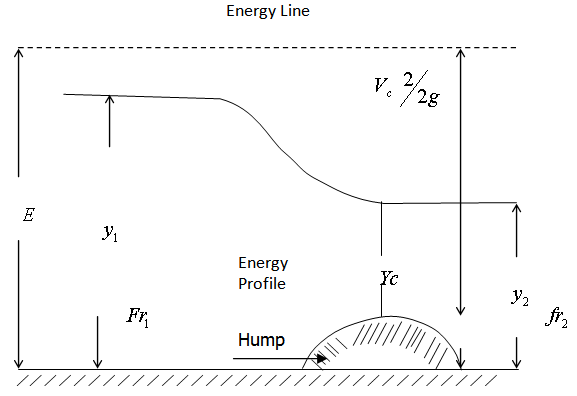 | Figure 1. Typical cross sectional profile of a hydraulic jump |
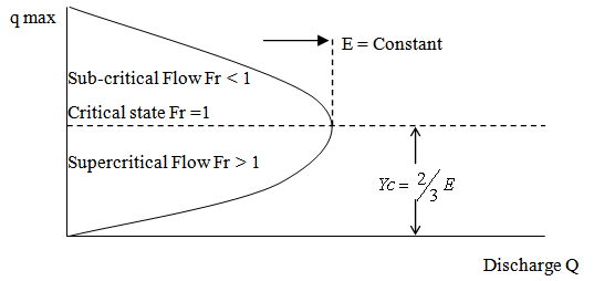 | Figure 2. Rigimes of flow due to variation in froude number of a flow |
Hydraulic jump can occur as moving hydraulic jump or stationary hydraulic jump. For example, tidal bores are hydraulic jumps ranging from andular wave front to a shock-wave-like wall of water. Stationary hydraulic jumps are surges in channels, spillways, sluice gates weirs and cascading rolling waves. In this paper stationary hydraulic jump is treated.Characteristics of Hydraulic Jump. The following characteristics of hydraulic jump enable its understanding and subsequent analysis, they include:1. Energy loss:Change in momentum due to change in flow regime results to abrupt Charge in energy, from higher energy level to lower energy level. The rate of energy dissipation or head loss across a hydraulic jump is a function of the in flow (upstream) froude number. (CE404, 2012, Hayawi and Mohammed, 2011; HEC 14, 2011; Hubert, 2011; Rajput, 2011, Harlan 2010, Leton, 2005). The higher the jump, the greater the head loss. This head loss is the difference in the specific energies before (upstream) and after (downstream) the jump. It is express as: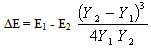 | (2) |
2. Height of Jump.The difference between the depths after and before the jump is the height of the jump. That is,  | (3) |
Expressing Equation (3) as ratio with respect to initial specific energy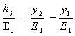 | (4) |
Expressing in terms of dimensionless functions of froude number of in flow, Fr1. 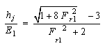 | (5) |
Substituting equation (5) in Equation (4)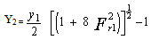 | (6) |
 | (7) |
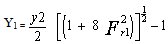
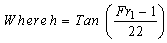
3. Length of Jump It is the distance, L measured from the face (front) of the jump to the point on the surface immediately downstream of the jump. The work of chow (1959) as presented in Leton (2005) states that length of jump in rectangular channel is six times the sequent jump height that is L = 6 y2 (for froude number range of  However, he further states that for froude number outside this range, the length is some what less than 6y2. For this reason, length of jump has been obtained from charts developed from curves of L/y2 versus Fr1. Lefebure (1986) provided curves for sloping channels. The most reliable relation in use are:
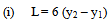 | (8) |
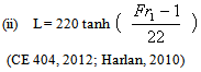 | (9) |
4. Efficiency of JumpThe ratio of the energies after and before the jump gives the efficiency of the jump.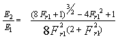 | (10) |
Equation 10 shows that the efficiency is a dimension less function, depending only on the Froude number of the approaching flow. The relative energy loss is also a dimension less function given as 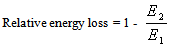 | (11) |
5. Surface Profile of JumpKnowledge of the surface profile is desirable in designing free board for the retaining walls of the stilling basin where the jump takes place. It is important also for determining the pressure for the design of the structural member because experiments have shown that the vertical pressure on the horizontal floor under a hydraulic jump is practically the same as would be indicated by the water – surface profile (HEC14, 2012;) CE 404, 2012).6. Location of JumpHydraulic jump occurs in a supercritical flow where the depth changes abruptly to its sequent depth.7. Froude NumberIt is a dimensionless number that depends on velocity of flow, depth of flow and acceleration due to gravity. That is  For hydraulic jump, all the variables depend on froude number of the approach (down – stream) flow such as relative energy loss, efficiency, relative height, initial and sequent depths. The approach or initial Froude number is given as:
 | (12) |
Where V12 = approach flow velocity, g = acceleration due to gravity, y1 = depth or height of initial or approach flowFroude number determines the regime of flow in a flowing water in a channel, thus (i) For Fr < 1, the flow is subcritical (Tranquil or streaming flow)(ii) For F1 = 1 the flow is critical (normal in flow)(iii) For Fr >1, the flow is supercritical (turbulent and shooting in flow).Figure 2 shows regimes of flow due, to varying froude number. Types of Hydraulic JumpHydraulic jump only occurs when the incoming (initial or approach) flow is supercritical, that is, when Fr1 > 1. Increasing froude number of the incoming flow above unity brings about changes in hydraulic jump formed due to disturbances with corresponding differences in loss of energy. These are conveniently classified as types of hydraulic jump. They are:(i) Fr1 = 1.0 – 1.7, undular jump: the water level shows undulation(ii) F = 1.7 – 2.5, weak jump: a series of small rollers develop on the surface of the jump, but the downstream water surface remains smooth. The velocity throughout in the jump is fairly uniform, and the energy loss is low.(iii) Fr1 = 2.5, - 4.5 oscillating jump there is an oscillating jet of water entering the jump bottom to surface and back again with no periodicity. Each oscillation producing large irregular period. This can travel long distance doing unlimited damage to earth banks.(iv) Fr1 = 4.5 – 9.0, steady jump: the downstream extreme of the surface roller and the point at which high velocity jet tends to leave the flow occur practically at the same vertical section. The action and position of this jump are least sensitive to variation in tailwater depth. The jump is well balanced and the performance is at its best. The energy dissipation ranges from 45 to 70%(v) Fr1 ≥ 9.0, strong jump: the high velocity jet grabs intermittent slogs of water rolling down from the face of the jump, generating waves downstream, and a rough surface can prevail. The jump action is rough but effective since energy dissipation may reach 85%. Youngkyu K et al (2015) showed the variations or types of jump that can occur naturally or generated artificially.
3. Model and Methods of the Work
The models used in the work are hydraulic principles of energy equation as modified to exclude pressure energy (CE404, 2012) that is,  | (13) |
Momentum equation (Leton, 2005) that is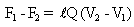 | (14) |
The equations of hydraulic jump computation were represented in VB codes and the required programme written and run to obtain specific results.
4. Conversion of Model Equations to Visual Basic Code
Specific Energy (E)Potential energy = h = y = depth, Kinetic energy =  Specific energy of flow = y +
  Where y = Depth of flow, V = Velocity of flow, g = Acceleration due of gravity Conversion,
 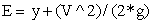 or
or 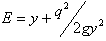 Given that
  Where q = Discharge per unit width, Q = Discharge through the channel, b = Width of the channel Conversion,
 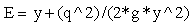 Critical Depth Yc
 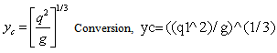 Critical Velocity Vc
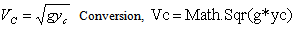 Minimum Specific Energy (Emin)
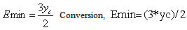 Froude Number Fr
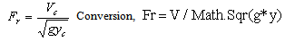 Sub Critical, Critical and Supper Critical Flow When
  It is a sub critical (The flow is tranquil or streaming),
  It is critical flow (The flow is critical)
 It is super critical (the flow is shooting) NB. Critical depth allows for maximum discharge i.e At critical depth there will be maximum discharge Height of the Jump (Hj)
 Where Hj = height of the jump, E = specific energy in normal flow, E min = Minimum specific energy an
 Hydraulic Jump of Standing Wave in Terms of Depth
 that is Height of jump
  Where Y1=Initial depth and Y2 = Final depth
 Conversion,
  Length of Jump (Lj) The length of jump fall within 5 to 7 Hj (for rectangular channel with horizontal floor).Also from thorough analysis and experiments the length of jump can also have the following relationship
 Conversion,`
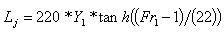
 Head LossLoss of energy due to hydraulic jump (Head loss) Where Y2 = Find depth and Y1= Initial depth
 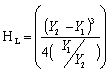 Conversion,
 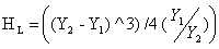 Strenght of JumpStrength of jump =
  Conversion,`
  Power Dissipatedpower dissipated
  Where w = specific gravity of water = 9810, Q = Discharge through the flow and
  Maximun Length of Hump
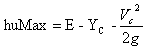 Conversion,`
 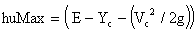 Contraction WidthContraction width (bc) is
 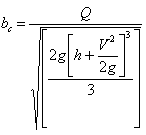 Conversion,`
 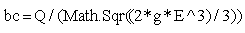 Efficiency Of The Jump The efficiency of the jump is
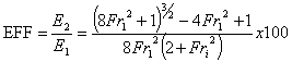 Conversion,`
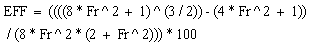
5. Program Listing (Visual Basic Programming)

6. Case Study
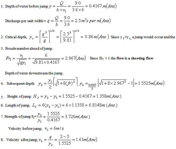
Having designed the program let us take a case study of a rectangular channel of about 3-6m wide discharging 9.0 m3/s of water with a velocity 6.m/s and analyses for all the characteristics of the jump manually by calculating and compare the result with the modeled program.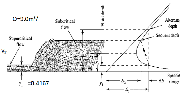
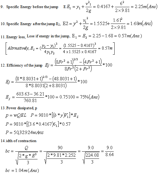
7. Manual Computation
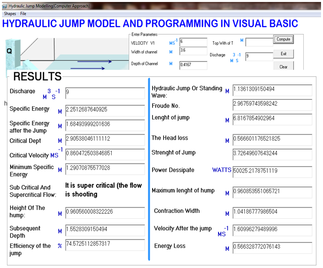
8. Program Output
9. Discussion
It is necessary to discuss on how to use the program.The program is written and compile with visual basic 6.0. Also it is written to a storage device (CD –ROM). The program can be access directly from the CD-ROM drive and can run on any machine install with Microsoft windows (Operating System), e.g., windows XP, Window 7, Window Vista etc. Also the program is user friendly (users can make use of standard keyboard and mouse).
10. How to Run the Program
1. Click on the start button2. Click on my computer3. Double click on CD-ROM/DVD ROM DRIVE4. Double click on the file (Project.exe)5. The program displays the welcome window and start loading the login window. See figure 1.0 below. 6. The login window show
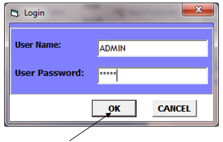 7. To access the main program window, the user must provide a user name and password. The user name used here is “ADMIN” and password “ADMIN”. Notice; the username and password are case sensitive.8. Click the ok button9. The main program window display. see figure 2.0
 10. To start computation, select the shape from the shape menu
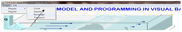 11. The user can select and of the shapes, here rectangle is selected12. Enter the parameters. See figure below.
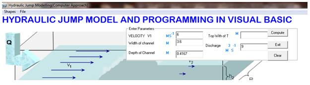 13. To make changes, if the data entered in the text are not correct14. Click Clear15. Repeat step 1216. Click compute button17. The result is shown below.
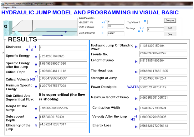 18. To print the result, click on File menu and select print.
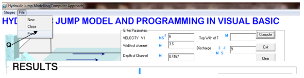 19. To end the program, click on file menu and click close.
11. Summary
From the result it was observed that the output of the programme and the manual analysis of the case study are the same. The in flow is a shooting flow since froude number is greater than one. It is an oscillating jump since the froude number is 2.97 (Fr1 = 2.5 to 4.5). There is an oscillating jet entering the jump bottom to surface and back again with no periodicity. Each oscillation produces a large wave of irregular period which can travel for kilometers doing unlimited damage to earth banks.The specific energy before is higher than the specific energy after the jump due to energy loss. It was 2.25m before the jump and 1.68m after the jump as a result of the energy loss of 0.57m. The flow after the energy loss changed from suppercritical to subcritical flow, producing tranquil or steady flow that can reduce uplift pressure under the foundation of hydraulic structures. The hydraulic jump, length of the jump and strength of the jump produced are 1.14m, 6.82m, and 6.63 respectively which can enhance irrigation water supply, mixing of chemicals for water purification, aerate water for water supply treatment and removal air pockets from water supply lines. The power dissipated is 50,025.22 watt which can prevent possible erosion and scouring downstream of the structure due to reduced velocity.
12. Conclusions
It is observed that when the Froude number is less than one the flow becomes a subcritical flow and no hydraulic jump will occur. The higher the velocity of flow with constant depth and width of the channel the higher the Froude number. The higher the Froude number the higher the other characteristics of the flow except energy loss.The energy loss is influenced by the depth and width of the channel. The lower the depth the higher the head loss and the higher the depth, the lower the head loss.
13. Recommendations
I recommend this model for use sequel to the fact that the following can be achieved.-The cumbersomeness of manual computation of hydraulic engineering problems that involve so much iterations that led to waste of time and cost were modeled for optimal maximization of profit.-It will analyze automatically and produce the desired Froude number that can enable the engineer to determine the nature of the flow-The velocity of flow required to produce the desired jump for irrigation purpose can be achieved -It can be used to determine the jump that can mix, aerate and purify water and waste water for effective treatment.-The power dissipated can be used to prevent erosion, uplift of foundation and scour velocity.-Easy analysis and design results can be achieved.-Fast engineering consulting services
References
| [1] | Blackwell, A.F. (2002) what is programming. In Kuljis, J, Baldwin L. and scoble, R (eds). Programming Journal Proc. PPIG. Vol. 12. pp. 204 – 121. (www. webopedia. Com / TERM / p/ programming Language. html). |
| [2] | CE 404 (2012) Hydraulic structures – Hydraulic. Pp 3.1 – 3.7 www. hyd. Uod. Ac/%3Fcat% 3 D6. |
| [3] | Chanson, H. (2004). The Hydraulic of Open Channel Flow: an Introduction (2nd ed.). Butterworth. |
| [4] | Chow, V. T. (1959) Open channel Hydraulics. McGraw – Hill, New York. |
| [5] | Douglas, J.F. Gasiorek, J.M; and Swaffield, J.A (1995) Fluid Mechanics. 3rd ed. Longman. Singapore pp 496 – 499. |
| [6] | Douglas, J.F.; Gasiorek, J.M.; Swaffield, J.A. (2001). Fluid Mechanics (4th ed.). Essex: Prentice Hall. |
| [7] | Erik Martens (2012) Model for polygonal hydraulic jump, max-planck-Gesellschaft institute, jounal of hydraulic research, page1 & 2 10.1103/PhysRevE.85.036316 www.mpg.de/5791959/polygonal_hydraulic_jump. |
| [8] | Falex Inc. (2012). Definition of programming. (http:// www. the reedutionary com/ modeling). |
| [9] | Falex Inc.(2012) modeling, model, and representation Http//www.thefreedictionary.com/modelling |
| [10] | Ford, A. (2009) Modeling the environment 2nd ed Island press, Washington D. |
| [11] | Faulkner, L.L. (2000). Practical Fluid Mechanics for Engineerring Application. Basil, Switzerland: Marcel Dekker AG. |
| [12] | Fox, “R.W. and McDonald, A.T. (1992). Introduction to Fluid Mechanics. 4th edition. John Wiley and sons Inc. New York. Pp 124 - 127 |
| [13] | Harlan, Bengtson (2010) Open channel flow: Basic Hydraulic Jump calculations. (edited) Jamar stonecypher. Bright Hub Engineering Publisher, journal. (www. strartaDraw. Com.) |
| [14] | Hydraulic Engineering Grcular, HEC 14 (2011) Hydraulic Design of Energy dissipater for culverts and channels. United State Department of Transportation. Federal Highway Administration HEC 14 Hydraulic Engineering – FHWA. |
| [15] | Hydraulic jump calculations in Rectangular Horizontal channel (http : // www. Imnoenq. Com / channels/ hydraulic jump. Htm). |
| [16] | Hydraulic jump in Rectangular channels (2010). enwikipedia. Org/wiki / Hydraulic–Jump–in–rectangular–jump, 2010, -11–10. |
| [17] | Hayawi, H.A. and Mohammed, AY (2011). Properties of Hydraulic Jump Downstream shice Gate. Research Journal of applied science, Engineering and Technology. Volume 3 No 2. pp 81 83. |
| [18] | Hubert, C. (2011) Air bubble entrainment in hydraulic jumps: Physical modeling and scale effect. (ed) Lanzoni, S. and Silvio, G. (www. escape. Library up. an / eserv. Php%). |
| [19] | Khatsuria, R.M. (2005). Hydraulics of Spillways and Energy Dissipaters. New York: Marcel Dekker. |
| [20] | Legogo, A. B (2012): Terrain model of Bori Town for drainage management Using GIS technologies. Master degree thesis. Department of Civil Engineering. University of Port Harcourt. April, 2012. |
| [21] | Lefebvre, J. (1986) Measure des Debits et des vitresses de flumes. Mason, S.A. Paris. |
| [22] | Lopez, D., Marivela, R. & Garrote, L. (2009) Smoothed particle hydrodynamics model applied to hydraulic structures: a hydraulic jump test case, Journal of Hydraulic Research, 47 (extra issue), 142-158. |
| [23] | Numerical study of a turbulent jump (2004). (http: // www. coastal. Udel. Edu / zhao / ems 2004. pdf). |
| [24] | Orton, R. (2012) What is model. Starting point – Teaching entry level, Geoscience. (www. brc.dcs. gla. Ac. Uk/…/modelling) 050301 – Richardordon6up. PDF). |
| [25] | Rajput, R.K. (2011) Fluid Mechanics and Hydraulic of Machines. S. chard and Company Publishing Ltd. 4th ed. |
| [26] | Youngkyu Kim, Gyewoon Choi, Hyoseon Park and Seongjoon Byeon, Hydraulic Jump and Energy Dissipation with Sluice Gate, Water 2015, 7, 5115-5133; doi:10.3390/w7095115 www.mdpi.com/journal/water. |

 Abstract
 Reference
 Full-Text PDF
 Full-text HTML