Meysam Motahari1, Farid Ejlali2, Mohamad Javad Alizadeh3, Mehdi Kouchakzadeh4
1MSc, Faculty of Agricultural Engineering, Tarbiat Modares University, Tehran, Iran
2Assistant Professor, Payam Nour University, Tehran Branch, Tehran, Iran
3Department of Civil and Environmental Engineering, AUT, Tehran, Iran
4Associate professor, Faculty of Agricultural Engineering, Tarbiat Modares University, Tehran Branch, Tehran, Iran
Correspondence to: Meysam Motahari, MSc, Faculty of Agricultural Engineering, Tarbiat Modares University, Tehran, Iran.
| Email: |  |
Copyright © 2014 Scientific & Academic Publishing. All Rights Reserved.
Abstract
For drying paddy soils, underground drainage system is imperative and the application of theoretical equations in design of underground drainage system is not efficient for all farms, either, therefore, the construction of experimental farms prior to the massive construction projects is inevitable. To determine the underground drainage system parameters in paddy experimental fields of human resources and agricultural development center of Mazandaran Province, Iran, becomes to the main goal of this study. Owing to the excessive rainfall in these regions, the fluctuation of water with its corresponding none-steady state happens. To achieve the goal on the construction of experimental farms, underground water surface level was measured in an area of about 11700 square meters, equipped with underground drainage system in 15 meters distance and 70 centimeters depth. Tests onthe soil texture with its hydraulic conductivity were additionally conducted in these regions. Regarding to the proper reaction of the drainage system to the precipitation events, the most efficient underground drainage system was derived for the adjacent area with relevant results of the immediate reaction ratio and specific discharge.
Keywords:
Specific discharge, Paddy fields, Unsteady methods, Underground drainage, Reaction ratio
Cite this paper: Meysam Motahari, Farid Ejlali, Mohamad Javad Alizadeh, Mehdi Kouchakzadeh, Application of Unsteady Approach in Determination of Design Parameters of Underground Drainage System (Case Study: Experimental Farm of Human Resources and Agricultural Development Center, Mazandaran, Iran), International Journal of Hydraulic Engineering, Vol. 3 No. 2, 2014, pp. 61-67. doi: 10.5923/j.ijhe.20140302.02.
1. Introduction
Despite of many advantages of land integration in North of Iran, which expedite in planting, harvesting and production of rice, the insufficiency of surface drainage systems in controlling the water surface depth should be investigated for cultivation of other crops in wet seasons. On the other hand the high water table, made it difficult or impossible to use the heavy machinery such as combines. In this regard, applying the underground drainage systems is vital to overcome the above mentioned problems [12]. Draining the excess water in certain periods of rice growth increases the crop production. Anyway the main purpose of using this type of design is to provide appropriate conditions of rice cultivation in this region. Moreover, the design of the drainage system for rice paddies and other crops depends on several factors which cannot be easily accomplished. The most common method of subsurface drainage in paddy fields is the use of a pipe system as it applies in Japan. This underground drainage system is equipped with valves which can get closed to raise the water table on lands [1]. In this method of draining, a novel definition of drainage systems which is the draining control of excess water has been taken into consideration. Several researches have been conducted to investigate several factors which can influence drainage systems design. Walker et al have [13] introduced factors such as, effective porosity, hydraulics conductivity, and drain spacing which are effective on drop of the water table in the Illinois, US region. In order to estimate effective porosity primarily raised the water table to ground surface, and at this stage they stopped irrigation and started to measure water table drop and drain outflow simultaneously. Results showed an effective porosity of about 0.034 to 0.0483, and hydraulic conductivity of 19 to 63.2 mm/day. Safwat et al. [9], have evaluated North eastern Nile Delta land drainage systems. These investigations show that the actual hydraulic conductivity values are twice of measured values, and also they demonstrated that the drain intensity and impervious layer depth are more than designed values. The efficiency of another drainage system has been evaluated by the measurement of drain outflow and water table between two drains for a period of 4 years (1994-98) in Livonia Remidis & Drerickx [8]. Results showed that, drain spacing in entire plots was considered excessively. Several other investigations have been reported in Iran, mansour isaranjibaneh [7], has assessed the drainage system design parameters, in a sugarcane cultivation field, which reported positive results of water table control. Evaluating the measured value of effective porosity instead of investigating the hydraulic conductivity shows acceptable compliance. On the other hand, behshahr Ebrahimian et al [4] investigated the irrigation system of Behshahr Run, agricultural fields, using piezometer planting, results show low efficiency of the drainage system. Evaluation of subsurface drain system in pilot projects, have achieved to accurate values of the design parameters. So that employing these values could lead efficient implementation of drainage systems. In this study, attempt has been made to achieve the optimal values of design parameters for underground drainage system. To do that, field measurements have been carried out for the case study of Haraz region as well as assessing the efficiency of the drainage system. To achieve the most efficient results of design parameters, non-steady state Glover Damm equation was used.
2. Materials and Methods
2.1. Study Area
This study was conducted in Haraz human resources and agricultural development experimental fields, with the geographical coordination of 52.17 Eo and 36.58 No. . The study region is located at a height of 5.5 meters above sea level and has an average annual rainfall of 865 mm and maximum , minimum and average temperature of 38, -5 and 17℃(3) respectively. Figure 1, illustrates the study area and its location. 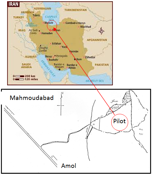 | Figure 1. Human Resources and Agricultural Development Center’s Experimental Fields |
2.2. Procedures and Measurements
This study was carried out in an area of about 11700 square meters (in three experimental plots), which was equipped with underground drainage system. The spacing of the draining pipes with a diameter of 125 mm, was about 15 meters and they were located in a depth of 70 centimeters. To measure the water table, 15 observation wells were drilled to a depth of one meter and on the other hand in order to measure draining discharge, volumetric flow meters were installed at the draining outlets. Figure (2) illustrates the location of the underground drainage system and observation wells schematically.
2.3. General Characteristics of the Region
2.3.1. Soil Texture
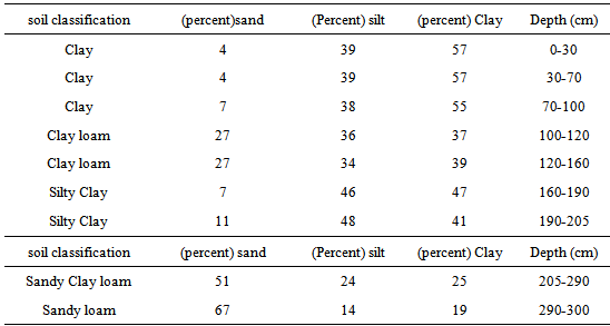
During the measurements of water table drop and draining flow, nine soil samples from different depths were taken adjacent to each observation wells. The results are shown in the following table:Table 1. Soil Texture tests of Haraz center experimental fields
 |
| |
|
Soil texture is lighter, deep in the ground. Paddy soil type reported by Iranian researcher in Rasht, are generally different from the soil texture tested in this study. However it seems that the Mahmoudabad paddy soil has lighter texture.
2.3.2. Hydraulic Conductivity
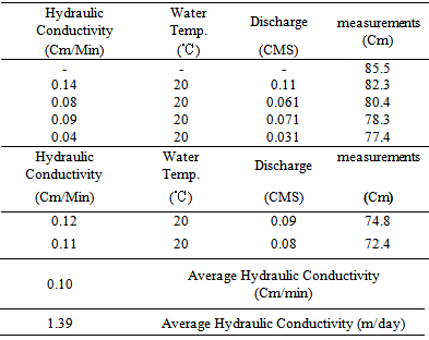
Soil hydraulic conductivity results’ using field measurements, which have been measure in six days are presented in table (2). In this method a 220-liter calibrated tank with a recorder attached to a cork is used.Table 2. Results of soil hydraulic conductivity measurements in Haraz experimental fields using above water table method
 |
| |
|
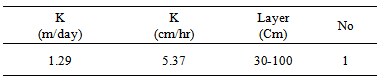
For depth of 30-100 well method was used, the results are as follows:Table 3. Hydraulic conductivity measurement test results for 30 – 100 cm depth using well method
 |
| |
|
Hydraulic conductivity of the soil at the experimental farm makes the water pass through soil pores and enter the underground drain line.
3. Underground Drainage Design Parameters
Underground Drainage systems can be done using steady flow and none steady flow equations. In the first method it is assumed that the draining outflow is equal to rainfall, while in the other, the flow in soil is a function of time and thus the soil water table fluctuates. In this study none steady flow equations were used.
3.1. None-Steady Flow Conditions
In this study, the none-steady condition of Glover-Damm equation was used. In order to determine water table between two pipe drains (ht) at time t=t the following equation is used: | (1) |
Where:dt is the duration in which water table rises from h0 to ht (days), h0 is the primary hydraulic water table at t=t0 (m), ht is the hydraulic water table at t=t (m), μ specific discharge (drainable porosity) (%).
3.2. Measuring the Desired Parameters
To measure the water table fluctuations between drainage lines, 15 wells were drilled in six drain lines and to measure the outflow rate a volumetric contour was used, Figure (2). For this purpose, drain outlets kept closed before the precipitation that caused the rise in water table and after the cessation of the precipitation, drain outlets were opened to measure the outlet discharge and water table depth. The measurements continued to the moment that the outlet discharge was negligible. | Figure 2. Observation wells location among the drainage system lines |
4. Results and Discussions
4.1. Volumetric Contour Calibration
Regarding the common errors on measurements of the volumetric contour at low discharges, the volumetric contour used in the test was calibrated with the volumetric method. Results of the calibration are shown in figure (3). | Figure 3. Volumetric contour calibration using measured volumetric method |
For this purpose contour data were recorded and at the same time drain outflow discharge were measured, results are presented in table (3).
4.2. Discharge Hydrograph
Data recording started immediately after opening the drain outlets, results and time of data recording are presented in table (4).  | Figure 4. Discharge Hydrograph for 3 days period, (05 to 08 December- 2010) |
4.3. Water Table Hydrograph
In order to draw the water table hydrograph, data obtained from the wells drilled between drainage line were used. Well drilled at a distance of 5.57 meters which is shown in red at figure (2), is the middle of the lateral and experimental farm. The distance between this point and four other points are 17.5, 37.5, 77.5 and 97.5 meters respectively. The reaction coefficient is measured at five different linear distances. Water table hydrograph for the five distances of all plots were calculated. Calculated results for the plot on the middle are presented in figure (5).  | Figure 5. Water table Hydrograph for the middle plot of the experimental field |
According to Figure 5, it can be observed that with increasing in distance among wells, h decreases with higher intensity. Also, it can be derived that the values of h decreases as time goes for all well spacing values.
4.4. Assessment the Design Parameters of Underground Drainage System
The logarithmic values of water table between two drains in different longitudinal distance from the lateral are measured in three plots. Figure (6) shows the results of the middle plot and figure (7) is a logarithmic plot of the drain outlet discharge over time. Due to Glover equation, Slope of logarithmic water table plot (or drain outlet discharge) over time, is equal to drainage network response coefficient. It is clear that the drains are closer to ground surface; the higher is the response coefficient. In other words, the observation wells in a distance of 97.5 meters, have higher response coefficient, compared to other observation wells in three other experimental plots. Finally, the average response coefficient of drains on the middle of the drains (57.5 meters) in all the plots are considered to be the response coefficient of the underground drainage system, which is ([0.94+1.36+1.67]/3) or 1.33 1/day. After the determination of the response coefficient of the drainage network, the specific discharge is calculated with the following equation, which, in this study is 4 percent.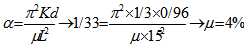 | (2) |
Response coefficient for fields with low response is 0.2 to 0.3 where this coefficient for immediately reaction fields is 2 to 5 (11). As a result, the response coefficient of the Haraz center underground drainage network shows an almost immediate reaction of the field. The reason for this immediate reaction of the field, due to Glover Dam equation can be for the high value of Kd and low value of L or μ. it seems that the close spacing between drains of underground drainage system in the experimental field is the most important reason of the appropriate reaction response. Considering figure (7), the response coefficient, determined by the outlet discharge is 0.95 and difference occurred with this method and the method of discharge measurement, could be the possible errors). The more values of μ coefficient conclude, to greater values of water storage in the soil profile. With the assumption of constant drainage depth, it can be seen that μ and water storage in soil profile has a direct relationship. To get the desirable conditions, greater values for design discharge or closer space for drains should be taken into account.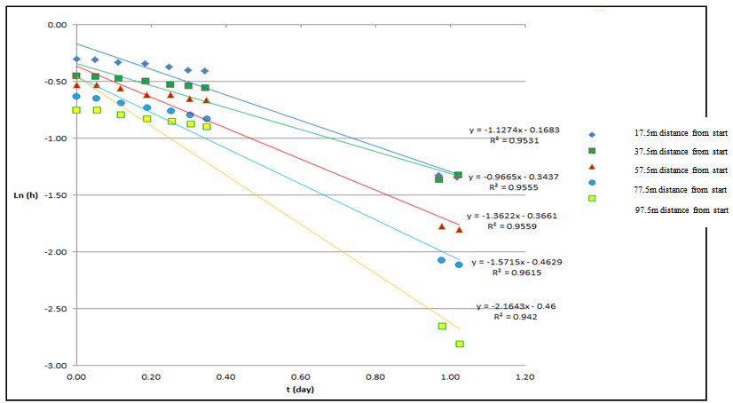 | Figure 6. Logarithmic plot of water table between two drains at different longitudinal distances over time |
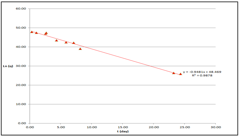 | Figure 7. Logarithmic plot of outlet discharge over time |
The soil texture of the experimental filed was so different from the previous reported paddy fields, and the reason is the close distance to the sea shore. Despite of the drainage problems in the adjacent fields, the experimental paddy fields which were conducted to the study had an acceptable drainage system. Therefore, for the farms that are near to the shore, water table can be affected by the shore condition and well drainage can be a good solution.
5. Conclusions
In this study, the applicability of underground drainage systems in paddy fields has been taken under consideration. The experimental field could present all the characteristics of adjacent agricultural field and the results can easily be generalized in design of drainage systems in the other regions. Findings of this study show that a drainage network system with a space of 15 meters and a depth of 70 centimeter is the ideal drainage system forth is area. In order to get a better result for any region, more field study work should be done. According to the current study, it seems that close space between drains of underground drainage system in the experimental field is the most important reason of the appropriate reaction response. Regarding to this study, applying the non-steady flow conditions can predict the water table efficiently. Comparison of measured values of water table with the values obtained from the equation show good agree of similarity.
ACKNOWLEDGEMENTS
Hereby sincerely cooperate with experimental of the Center for Human Resource Development and Agricultural center, especially Mr. Najafi, the implementation of this research Acknowledgments practice comes perfection.
References
| [1] | Alizadeh, A., 2003, (In Persian), Land drainage, Plan drainage system in agricultural planning. Fifth Edition. Publications Astan Quds Razavi, 448 pages. |
| [2] | Bayboardi, M., 1999, (In Persian), Engineering principles to improve drainage and soil, Eighth Edition, Tehran University Press, 641pages. |
| [3] | Darzi,A., 2005, (In Persian), Evaluation of an underground drainage system in paddy fields using software DRAINMOD, Completed a master, Aboureihan campus, Tehran University. |
| [4] | Ebrahamian, H.,2007., (In Persian) Performance Evaluation of an underground drainage system with rice husk, Case Study: Behshar, Completed a master, Branch campus, Tehran University. |
| [5] | Hann P. K., and Skaggs, R.W., 2003, Effect of parameter uncertainty on DRAINMOD predictions, I. Hydrology and Yield., Transactions of the American Society of Civil Engineers, 46(2): 1061-1067. |
| [6] | Kohler, A., Abbaspour, K.C., Fritsch, M., and Schulin, R. 2001,Functional relationship to describe drains with entrance drainresistance, Journal of Irrigation and Drainage Engineering, American Society of Civil Engineers, 127(6):355-362. |
| [7] | Mansourisaranjiane, F., 2005, (In Persian), Underground drainage system design parameters of the irrigation and drainage projects Cane Development Plan, Completed a master Irrigation and Drainage, Soil and Water Engineering Faculty of Tehran University. |
| [8] | Remidis, A., and dierickx, W., 2003, Evaluation of subsurface drainage performance in Lithuania, Agriculture Water Management, 59: 15-31. |
| [9] | Safwat, A.D., 1998, Performance of some drainage system in the Nile Delta, ASAE Proceedings of the 7th Annual Drainage. |
| [10] | Sands, G., Wiersma, J., Fore,Z., Hurlyt, T., Kandel, H., and Jin, C., 2001, Reducing crop loss due to excess water in northwest Minnesota with subsurface drainage, In The drainage outlet, Minnesota Agricultural Experiment Station, Available at: http://doutlet,coafes.umn.edu/research/projects/reducing_crop_loss.htm. |
| [11] | Smedema, L.K., and Rycroft, D.W., 1983, Land Drainage Planning and Design of Agricultural Drainage System, London, UK: Bats ford. |
| [12] | Tabuchi, T., Hasegawa, D., 2004, Improvement of paddy field drainage for mechanization, Paddy and Water Environment, Tokyo, Japan. |
| [13] | Walker, P.N., and Wells, J.D., 1983, Pipe drainage of heavy soil, field evaluation, American Society of Agricultural and Biological Engineers, 26(1): 0112-0115. |
| [14] | Wenyen, W., Bing S., and zhilu, l., 1994, Drain Spacing calculation considering influence of evaporation, .Journal of Irrigation and Drainage Engineering, American Society of Civil Engineers, 120 (3): 563-572. |
 Abstract
 Reference
 Full-Text PDF
 Full-text HTML