International Journal of Hydraulic Engineering

p-ISSN: 2169-9771    e-ISSN: 2169-9801

2013;  2(5): 115-120

doi:10.5923/j.ijhe.20130205.05

Accurate Explicit Equations for the Determination of Pipe Diameters

Christos Babajimopoulos, George Terzidis

Department of General and Agricultural Hydraulics and Land Reclamation, Aristotle University of Thessaloniki, Greece

Correspondence to: Christos Babajimopoulos, Department of General and Agricultural Hydraulics and Land Reclamation, Aristotle University of Thessaloniki, Greece.

Email:

Copyright © 2012 Scientific & Academic Publishing. All Rights Reserved.

Abstract

The determination of diameter in pipe flow problems requires the use of diagrams or iterative solutions of the Colebrook – White equation. Diagrams are inaccurate because of reading errors and are impossible to use when the whole problem is going to be solved by a computer. Iteration type solutions can be very time consuming when large water distribution networks are involved. In this paper, accurate explicit equations for the determination of pipe diameter are developed. Two equations are presented, a simple and a more complex one. The maximum relative errors in the computation of the diameter, D,for 4x10³Re ≤108 and 10-5ε/D ≤5x10⁻² are 0.36% and 5.65x10⁻³ % respectively. It was found that the complex equation is far superior to other explicit equations available in the literature.

Keywords: Colebrook - White equation, Darcy – Weisbach friction factor, Friction factor explicit formulation, Explicit equation, Pipe diameter

Cite this paper: Christos Babajimopoulos, George Terzidis, Accurate Explicit Equations for the Determination of Pipe Diameters, International Journal of Hydraulic Engineering, Vol. 2 No. 5, 2013, pp. 115-120. doi: 10.5923/j.ijhe.20130205.05.

1. Introduction

Among other problems the following three problems arise in the design of pipe distribution systems: I) determination of discharge, Q; II) determination of the head loss, hf; and III) computation of the pipe diameter, D.
To solve these problems, the following three equations are required:
Continuity equation which states that Q is constant and given by:
(1)
Darcy-Weisbach equation
(2)
Colebrook – White equation
(3)
in which D=internal pipe diameter; V=average velocity; f=Darcy-Weisbach dimensionless friction factor; L=pipe length; g=acceleration of gravity; ε=equivalent sand grain roughness of the pipe wall; Re=Reynolds number (Re=VD/ν); ν=kinematic viscosity.
For smooth pipes, the Colebrook-White equation[6] yields:
(4)
while for large Reynolds numbers (Re→∞) it is asymptotic to the equation:
(5)
Equations (4) and (5) were derived by Karman[25] and Prandtl[18] respectively with a slight modification of the numerical factors to agree with the experimental data of Nikuradse[17]. It should be noted that the roughness ε in Karman and Prandtl’s equations is the diameter of the uniform sand used by Nikuradse to create the artificial roughness in his experimental pipes. Since roughness of commercial pipes is not uniform in size, distribution and shape, Colebrook suggested the “equivalent sand roughness’ which is the roughness ε that would satisfy Eq. (5) for large Reynolds numbers. Colebrook[6] also observed that the experimental data obtained with commercial pipes in the transitional zone can be represented by a continuous curve which is asymptotic to Eqs. (4) and (5). With this important observation Colebrook derived Eq. (3) by using Eqs. (4) and (5) without explanation of the additive property of the terms in the logarithm.
The Colebrook-White equation (3) is implicit in f requiring a numerical iterative procedure for its solution. This complexity does not affect the problem of type I (computation of discharge, Q) because Q can be computed by a closed-form equation:
By computing where the velocity V is estimated by Eq. (2), substituting in the right hand side of Eq. (3), and computing Q from Darcy – Weisbach equation, the following equation is derived for Q:
(6)
The computation of hf and D however requires the estimation of f. Iterative type solutions of Eq. (3) are time consuming, especially when large water distribution networks are involved. The Moody diagram[16] has been used very extensively, especially in the past. The use of this diagram has two main disadvantages: a) accuracy is limited because of reading errors in logarithmic scale; and b) it is impossible to be used in computer computations. An additional way of solving pipe flow problems without the previous disadvantages is the derivation of equations which give f explicitly in terms of the known variables.
There are numerous papers dealing with the explicit formulation of f in type II problems (computation of head loss, hf) when Q, D, ε,ν and L are given e.g. Jain[14]; Swamee and Jain[21]; Barr[1]; Haaland[12]; Romeo et al.[19]; Imbrahim[13]; Sonnad and Goudar[20]; Valiantzas [24]; Clamond[5]; Diniz and Souza[8]; Yildirim[27]; Brkić [3]; Brkić[4]; Danish et al.[7]; Giustolisi et al.[10]; Li et al.[15].
A general review of explicit functions of f and a comparative study among them is given in Yıldırım[26] and Fang et al.[9]. Explicit equations of f, however, which can be used for the solution of type III problems (computation of D) are really scarce.
In diameter estimation problems, the combination of continuity equation (1) and Darcy – Weisbach equation (2) gives:
(7)
where:
(8)
and S=hf/L.
Substitution of Eq. (7) into the Colebrook-White equation (3) gives:
(9)
where:
(10)
Equations (7) and (9) can be used for the computation of D when hf, L, Q, ε and ν are given. The estimation of f in Eq. (9) requires iterative type solutions, since the Colebrook-White equation (3), as it is transformed into (9), is still implicit in f.
It is the purpose of this paper to develop explicit and very accurate equations of f for the solution of pipe diameter problems.

2. Review of Available Solutions for the Estimation of the Pipe Diameter

Swamee and Jain[21] presented an equation which in terms of the parameters T and R (Eqs. (8) and (10)), is written as:
(11)
According to the authors this equation covers smooth turbulent flow, rough turbulent flow and the transition in-between. It is valid for 10-81/R ≤10-3, which corresponds to 3x10⁸Re ≥ 3x10³, and 10-6 T ≤10-2, which corresponds to 2x10⁻⁶ ε /D≤ 2x10⁻². For these ranges, D is estimated with an error ±2%.
Gulyani[11] presented a simple method that takes into account the effect of surface roughness on pipe diameter. For each case under study he proposes two bounding equations which apply for smooth and extremely rough pipes. He estimates then the diameter for a smooth pipe and a factor which depends on the real roughness of the pipe. By multiplying this factor with the diameter of the smooth pipe he receives an approximate value of the real diameter of the pipe.
Swamee and Rathie[22] using the Lambert Function W(x) and Langrange’s theorem derived a rather cumbersome exact equation for the computation of D consisting of a series with infinite terms. According to the authors the use of only three terms ensures a sufficient accuracy for all practical purposes. In terms of the parameters T and R this equation is the following:
(12)
where:
(13)
One of the previous authors in the same issue of the same journal (Swamee and Swamee[23]), presented also the following equation for the computation of the diameter:
(14)
According to the authors, Eq. (14) is valid for 10-81/R<∞, which corresponds to 0≤ Re ≤3x10⁸, and 10-6 T≤10-2, which corresponds to 2x10⁻⁶ ε/D ≤2x10⁻². For these ranges, Eq. (14) was found to yield D within an error of ±2.75%.
Bombardelli and Garcia[2] also investigated the hydraulic design of large diameter pipes studied by the Hazen- Williams formula. This equation, in contrast to the Darcy – Weisbach equation, includes a conveyance coefficient, which is constant for the pipe material and independent of the flow regime. They concluded that the use of the Hazen-Williams equation can lead to serious practical and conceptual implications in otherwise straightforward computations.

3. Proposed Explicit Equations

A data set of 2853 exact values of f was generated by solving numerically the Colebrook-White equation (9) for 4x10³R ≤ 4x10⁷. For each value of R, T was varied in the range 4x10⁻⁶ T ≤ 3x10⁻². The previous ranges of R and T correspond to 104≤Re≤108 and 10-5 ≤ε/D≤5x10-2. The coefficients for the two equations that are presented in this paper were estimated with the Least Squares Method in Matlab.
Absolute relative errors were estimated by the formula:
(15)
where fcw is the value obtained by the Colebrook – White equation.
Depending on the desired accuracy, two explicit equations for f are proposed here. The first equation has the form:
(16)
This equation has a mean absolute error of 1.8%, and a coefficient of determination, r2, greater than 0.999. When f from Eq. (16) is used for the computation of the diameter D according to Eq. (7), the mean absolute error in D is 0.36%.
The second equation is more complex in form, but also even more accurate than Eq. (16):
(17)
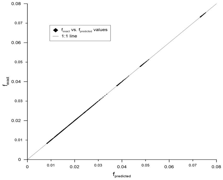
Figure 1. Predicted by Eq. (17) values of f versus exact values of f
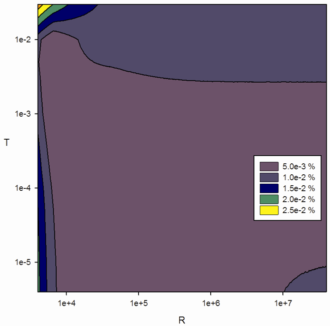
Figure 2. Distribution of relative errors of f estimated by Eq. (17)
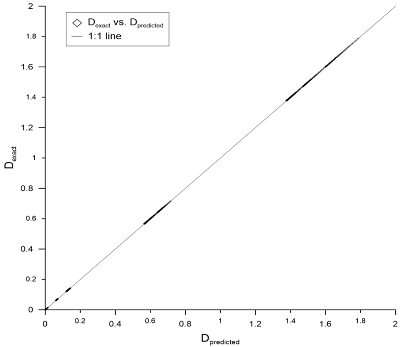
Figure 3. Predicted values of D (m) versus exact values of D. Friction factor f is computed by Eq. (17) and D is computed by Eeq. (7)
Table 1. Errors of the proposed equations in the computation of friction factor, f, and the diameter, D and errors of available in the literature equations
     
This equation has a mean absolute error of 0.028%, and a coefficient of determination, r2, also greater than 0.999. The mean absolute error in D as it is computed by (7) is 5.65x10⁻³. The accuracy of (17) is shown in Figures 1 to 3. Figure 1 shows exact values of f vs. predicted values of f and Figure 2 shows the distribution of the relative errors of f when it is computed by Eq. (17). The values of f are generated for 4x10³ ≤R≤4x10⁷ and 4x10⁻⁶≤T≤0.03. Figure 3 shows exact values of D vs. predicted values of D computed by Eqs. (7) and (17).
A summary of the errors of Eqs. (16) and (17) is given in Table 1. Table 1 shows also the errors of the aforementioned equations available in the literature. It is shown that Eq. (11) of Swamee and Jain[21] and Eq. (14) of Swamee and Swamee[23] give identical errors and they are the least accurate equations. Equation (12) of Swamee and Rathie[22] is substantially better than the previous two equations. It is obvious that equation (17), proposed in this paper, is the most accurate equation of all the previous ones.
To further assess the accuracy of Eqs. (16) and (17), a larger data set of 7957 values was generated by numerically solving the Colebrook – White equation (9) in the range 4*103 Re ≤ 108 and 10-5 ε/D ≤ 5x10⁻². It was determined that the errors never exceeded the corresponding values given in Table 1.

4. Conclusions

An explicit method for the computation of the diameter of pipes in pipe flow problems and in designing water distribution networks is very important. The two equations presented here for the computation of the friction factor, f, and, consequently, for the computation of the diameter, D, are very precise and superior to the ones presented in the literature, and can be used very easily for all practical cases.

References

[1]  Barr, D. I. H. (1977). "Discussion on "Accurate explicit equations for friction factor," by A.K.Jain." J. Hydraul. Div. Am. Soc. Civ. Eng., 103(3), 334-337.
[2]  Bombardelli, F., and Garcia, M. (2003). "Hydraulic Design of Large-Diameter Pipes." J.Hydraul.Eng., 129(11), 839-846.
[3]  Brkić, D. (2011a). "New explicit correlations for turbulent flow friction factor." Nucl.Eng.Des., 241(9), 4055-4059.
[4]  Brkić, D. (2011b). “Review of explicit approximations to the Colebrook relation for flow friction.” Journal of Petroleum Science and Engineering, Vol. 77, Issue 1, April 2011, 34–48.
[5]  Clamond, D. (2009). "Efficient Resolution of the Colebrook Equation." Ind Eng Chem Res, 48(7), 3665-3671.
[6]  Colebrook, C. F. (1939). "Turbulent flow in Pipes, with particular reference to the transition region between the smooth and rough pipe laws." J. Inst. Civil Eng., 11(4), 133-156.
[7]  Danish, M., Kumar, S., and Kumar, S. (2011). "Approximate explicit analytical expressions of friction factor for flow of Bingham fluids in smooth pipes using Adomian decomposition method." Communications in Nonlinear Science and Numerical Simulation, 16(1), 239-251.
[8]  Diniz, V. E. M. G., and Souza, P. A. (2009). "Four explicit formulae for friction factor calculation in pipe flow." Transactions on Ecology and the Wnvironment, 125 369-380.
[9]  Fang, X., Xu, Y., and Zhou, Z. (2011). "New correlations of single-phase friction factor for turbulent pipe flow and evaluation of existing single-phase friction factor correlations." Nucl.Eng.Des., 241(3), 897-902.
[10]  Giustolisi, O., L. Berardi, L., and Walski, T. M. (2011). "Some explicit formulations of Colebrook–White frictionfactor considering accuracy vs. computational speed." Journal of Hydroinformatics, 13(3), 401-418.
[11]  Gulyani, B. B. (2001). "Approximating equations for pipe sizing." Chemical Engineering, 108(2), 105-108.
[12]  Haaland, S. E. (1983). "Simple and Explicit Formulas for the Friction Factor in Turbulent Pipe Flow." J.Fluids Eng., 105(1), 89-90.
[13]  Imbrahim, C. (2005). "Simplified equations calculates head losses in comercial pipes." The Journal of American Science, 1(1), 1-2.
[14]  Jain, K. (1976). "Accurate explicit equation for friction factor." Journal of Hydraulics Division, ASCE, 102(HY5), 674-677.
[15]  Li, P., Seem, J. E., and Li, Y. (2011). "A new explicit equation for accurate friction factor calculation of smooth pipes." Int.J.Refrig., 34(6), 1535-1541.
[16]  Moody, L. F. (1947). "An approximate formula for pipe friction factors." Mech. Engng., 69 1005-1006.
[17]  Nikuradse, J. (1933). "Stroemungsgesetze in rauhen Rohren." Ver. Dtsch. Ing. Forsch., 361 1-22.
[18]  Prandtl, I. (1952). Essentials of fluid dynamics ,Hafner,New York.
[19]  Romeo, E., Royo, C., and Monzón, A. (2002). "Improved explicit equations for estimation of the friction factor in rough and smooth pipes." Chem.Eng.J., 86(3), 369-374.
[20]  Sonnad, J., and Goudar, C. (2006). "Turbulent Flow Friction Factor Calculation Using a Mathematically Exact Alternative to the Colebrook–White Equation." J.Hydraul.Eng., 132(8), 863-867.
[21]  Swamee, P. K., and Jain, A. K. (1976). "Explicit equations for pipe flow problems." J.Hydraul.Eng. ASCE, 102(5), 657-664.
[22]  Swamee, P. K., and Rathie, P. N. (2007). "Exact equations for pipe-flow problems" Journal of Hydraulic Research, 45(1), 131-134.
[23]  Swamee, P. K., and Swamee, N. (2007). "Full-range pipe-flow equations." Journal of Hydraulic Research, 45(6), 841-843.
[24]  Valiantzas, J. (2008). "Explicit Power Formula for the Darcy–Weisbach Pipe Flow Equation: Application in Optimal Pipeline Design." J.Irrig. Drain. Eng., 134(4), 454-461.
[25]  von Karman, T. (1934). "The fundamentals of the statistical theory of turbulence." J. Aero Sci., 4 131-138.
[26]  Yıldırım, G. (2009). "Computer-based analysis of explicit approximations to the implicit Colebrook–White equation in turbulent flow friction factor calculation." Advances in Engineering Software (1992), 40(11), 1183-1190.
[27]  Yildirim, G. (2010). "A MathCAD procedure for commercial pipeline hydraulic design considering local energy losses." Advances in Engineering Software (1978), 41(3), 489.