Bentalha Chakib
Department of Hydraulic Engineering, Abou Bakr Belkaid University, Tlemcen, Algeria
Correspondence to: Bentalha Chakib, Department of Hydraulic Engineering, Abou Bakr Belkaid University, Tlemcen, Algeria.
| Email: |  |
Copyright © 2012 Scientific & Academic Publishing. All Rights Reserved.
Abstract
Stepped spillway is a good hydraulic structure for energy dissipation because of the large value of the surface roughness. The performance of the stepped spillway is enhanced with the presence of air that can prevent or reduce the cavitation damage. The inception point in stepped spillway is the location where the turbulent boundary layer reaches the free surface. From this location air is entrained at the free surface. Chanson developed a method to determine the position of the start of air entrainment. The aims of this research are to validate the relationships developed by Chanson, to compare the velocity profile with one-sixth power law distribution and to present pressure contours and velocity vectors at the bed surface. Within this work the inception point is determined by using fluent computational fluid dynamics (CFD). The volume of fluid (VOF) model is used as a tool to simulate air-water interaction on the free surface thereby the turbulence closure is derived in the k −ε turbulence standard model. The found numerical results agree well with experimental results.
Keywords:
Inception Point, Fluent, VOF Model, Stepped Spillway, Standard k −ε Model
Cite this paper: Bentalha Chakib, Numerical Computation of Inception Point Location for Flat-sloped Stepped Spillway, International Journal of Hydraulic Engineering, Vol. 2 No. 3, 2013, pp. 47-52. doi: 10.5923/j.ijhe.20130203.03.
1. Introduction
Stepped spillway is a good hydraulic structure for energy dissipation because of the large value of the surface roughness. Rice and Kadavy[9] found from experiments on a specific model study of a stepped spillway on a 2.5(H):1(V) slope that the energy dissipated with steps was two to three times as great as the energy dissipated with a smooth surface, the studies of Rajaratman[16] and Christodoulou[11] demonstrated also effectiveness the stepped chute for dissipation of kinetic energy, thereby reducing the required size of the stilling basin at the toe of the dam. The performance of the stepped spillway is enhanced with the presence of air that can prevent or reduce the cavitation damage. The skimming flow regime down stepped chute is characterised by highly turbulence and the water flows as a coherent stream.In the skimming flow regime, air entrainment occurs when the turbulent boundary layer thickness coincides with the water depth[6]. This location is called the inception point (e.g. Figure 1). At the inception point upstream, the flow is smooth and glassy whereas at the downstream of the inception point the flow becomes uniform as the depth of the air-water mixture grows. The diffusion of air bubbles may be approximated by simple analytical model[6]: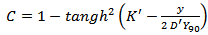 | (1) |
WhereC is the void fraction (or air concentration),tangh is the hyperbolic tangent function,y is the distance normal to the pseudo-invert formed by the step edges,Y90 is the distance where C= 90%D’ is a dimensionless turbulent diffusivity,K’ is an integration constant, and D’ and K’ are function of the mean air content only, where Cmean is the depth averaged air content defined in terms of Y90.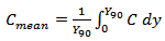 | (2) |
 | Figure 1. Position of the inception in stepped spillway |
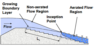
The inception point of aeration of stepped spillways is placed further upstream than on smooth spillways.On smooth spillway, the location of the inception point is a function of the discharge and the roughness of the spillway. Wood et Al[17] proposed an approach for determining the distance between the spillway crest and the inception point. On stepped spillway, the position of the inception point is a function of the discharge, spillway roughness, step geometry and spillway geometry. Chanson[5, 7] developed a method to determine the position of the start of air entrainment with slopes greater or equal than 22°. Boes and Hager[3] also derived a mathematical formula enabling the determination of the distance between the start of the turbulent boundary layer and the inception point.The position of the inception point is important element in determining the energy dissipation. Consequently, this position is a component in the dimensions of the stilling basin. At the downstream of the inception point, the dissipation of energy is very large. Hunt and Kadavy[13] found that the energy dissipation increases linearly from 0 to 30% upstream of the inception point (e.g. Figure 2).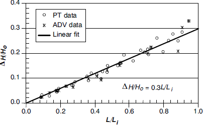 | Figure 2. Relative energy loss versus the observed normalized length (L/Li) obtained by Hunt and Kadavy[14] |
The topic of the flow over stepped spillway was the object of several experimental works, with the development of computational fluid dynamics (CFD) branch, flow over stepped spillway can be simulated to validate experimental results. Chen et al[10], simulated flow over a stepped spillway using the k –ε turbulence model. Benmamar et al.[2] developed a numerical model for the two-dimensional flow boundary layer in a stepped channel with steep slope, which was based on the implicit finite difference scheme. Bombardelli et al.[4] Simulated non-aerated region of the skimming flow in steep stepped spillways using 3D-FLOW. Afshin and Mitra[1] used FLUENT commercial software for examining the performance of the volume of fluid (VOF) and mixture models in simulating skimming flow over stepped spillway. Iman and Mehdi[15] evaluated energy dissipation in stepped spillways by taking into account parameters such as; number of steps, step height , horizontal step length , characteristic height of the step , flow discharge per unit and overall slope of stepped spillway by numerical method.In this study, flow over flat-sloped stepped spillway was simulated by using FLUENT software and VOF model was applied to evaluate air-water flow hydraulic characteristics. The aims of this work are to validate the relationships developed by Chanson, to compare the velocity profile with one-sixth power law distribution, and to present pressure contours and velocity vectors at the bed surface. The found numerical results are compared with the existing experimental results [13, 14].
2. Numerical Model
Fluent computational fluid dynamics (CFD) is used to solve Navier-Stokes equations that are based on momentum and mass conservation of the moving fluid. The standard k − ε model is used to simulate turbulence. Continuity equation: | (3) |
Momentum equation: 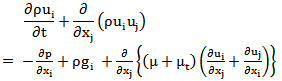 | (4) |
Turbulence kinetic energy equation (k):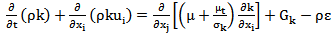 | (5) |
Turbulence dissipation rate energy equation (ε):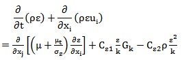 | (6) |
Where, Gk is production of turbulent kinetic energy which can be given as µt is the turbulent viscosity that satisfies
  Cμ=0.09 is a constant determined experimentally;σk and σε are turbulence Prandtl numbers for k and ε equation respectively, σk =1.0, σε=1.3, C1εand C2ε are ε equation constants, C1ε=1.44, C2ε=1.92.The volume of fluid (VOF) method is applied to simulate the free surface between water and air[12].In this approach, the tracking interface between air and water is accomplished by the solution of a continuity equation for the volume fraction of water:
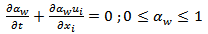 | (7) |
Where, αw is volume fraction of water.In each cell, the sum of the volume fractions of air and water is unity. So, volume fractions of air denote αa can be given as | (8) |
3. Results and Discussion
The geometry of numerical model and boundary conditions are shown in figure 3. The channel was 10.8m long and 1.5 m vertical drop. The channel slope is 14°. The stepped spillway contains 40 steps with 38 mm height and 152mm length by step. 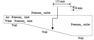 | Figure 3. Boundary conditions and numerical model of a stepped spillway |
In this study, several positions of the inception point are computed and compared with the existing experimental results[13] as well as with those predicted by the formula of Chanson[5]. The latter is a function of unit discharge, gravitation acceleration, channel slope (θ≥22°) and step height: | (9) |
Where:Li* = distance from the crest spillway to the inception pointθ = channel slopeF* = Froude number defined in terms of the roughness height:  q = unit dischargeg = gravitational constanth = step height.Figure 4 illustrates the volume fraction simulated by VOF model for unit discharge equal to 0.11, 0.20, 0.28, 0.42, 0.62, 0.82 m2/s. This figure indicates that the inception point moves toward the basin floor when the discharge increases. For unit discharge equal to 0.82m2/s, no air entrainment occurs along the chute because in high discharges, the boundary layer cannot reach the free surface at little distances, and the non-aerated region dominates large portions of the flow in the spillway. Based on Hunt and Kadavy[13], the inception point is located in basin floor for q=0.82m2/s, the air entrainment in this region may be caused by the hydraulics jump. For unit discharge equal to 0.62, 0.42, 0.28, 0.20, 0.11 m2/s, the inception point is located at 6.4, 4.4, 3.3, 2.5, 1.3 m respectively.
 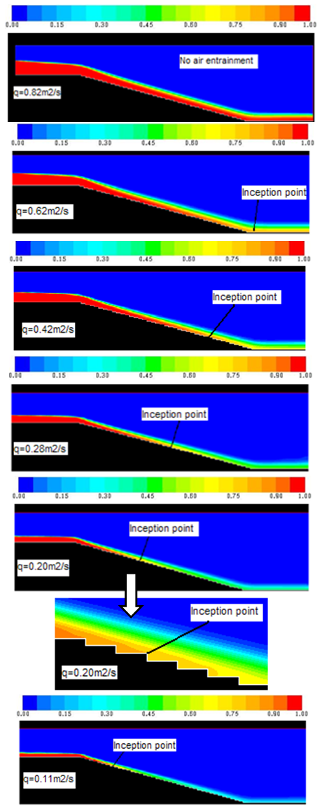 | Figure 4. Numerical computation volume fraction of water for different discharges |
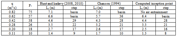
Table 1 summarises the position of the inception point found by Hunt and Kadavy[13], Chanson[5] and by using fluent, for unit discharge equal to 0.11, 0.20, 0.28, 0.42, 0.62, 0.82 m2/s.Table 1. Observed, calculated and computed inception point
 |
| |
|
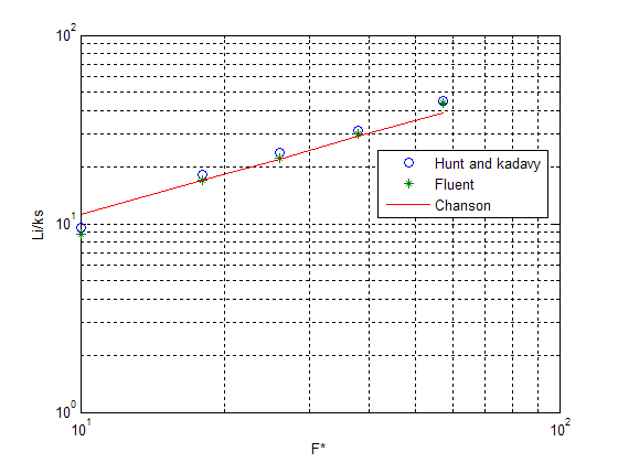 | Figure 5. Normalized Li versus Froude surface roughness, F* |
Table 1 and Figure 5 show good agreement between the predicted, observed and computed inception point locations. Hunt and Kadavy[13] proved that a relationship developed by H. Chanson[5] can be used to determine the inception point location on stepped chute with Froude surface roughness (F*) ranging from 10 to 100. They also proposed new relationships for determining the inception point for F* ranging from 1 to 100 with slopes little or equal than 22°: | (10) |
Figure 6 illustrates the location of the inception point observed by Hunt and Kadavy[13, 14] for q=0.28m2/s.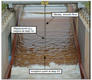 | Figure 6. Inception point at step 22 observed by Hunt and Kadavy for q=0.28m2/s |
The velocity distribution in stepped spillway is shown in figure 7. The velocity is higher in aerated region because the entrained air reduces wall friction; also the fluid is accelerated by the gravity along the chute. The recirculation flow which dissipates the energy in step corner is presented in figure 8. Most of the energy is dissipated by momentum transfer between the skimming flow and the eddy in the interior of the step.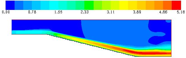 | Figure 7. Velocity distribution along the stepped spillway for q=0.28m2/s |
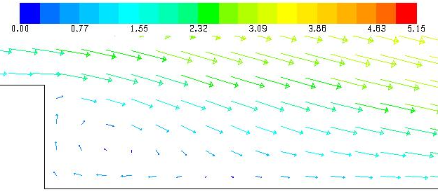 | Figure 8. Velocity vectors on one step for q=0.28m2/s |
The pressure distributions down the steps are important to study the risk of cavitation in stepped channel; figure 9 illustrates the contours of pressure in step corner. This figure indicate that the minimum value of pressure is located in the vertical wall of the step, is due by separation flow between skimming flow and the eddy in this region. Also maximum pressure exists in the horizontal surface of the step. This maximum pressure is caused by the impact of the skimming flow coming from upper step.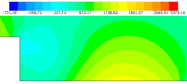 | Figure 9. Pressure contours on one step for q=0.28m2/s |
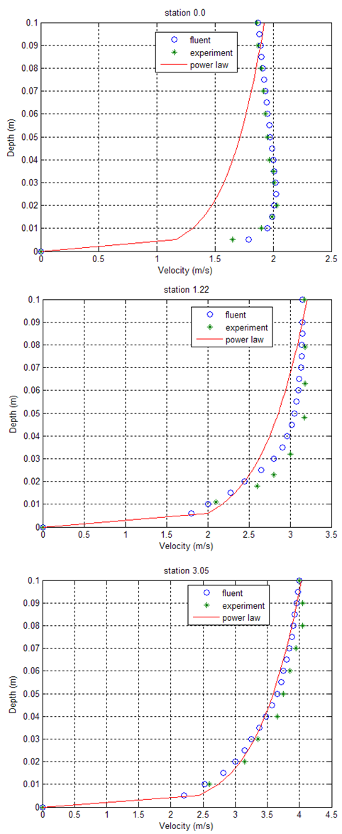 | Figure 10. Comparison of the one sixth power law with a Velocity obtained by simulation and measurement in Hunt and Kadavy[10] |
In figure 10, the one sixth power law with velocity was compared by velocity profiles obtained with fluent and the experimental velocity profiles measured by Hunt and Kadavy[14] at different distances from spillway crest 0.0, 1.22 and 3.05m respectively for q=0.28m2/s. This figure shows good agreement between experiments and simulations. The velocity profiles are uniform at the crest and trend toward a one sixth power law distribution near the inception point. Chanson[8] found from experiments that the velocity profiles tended to follow a one-sixth power law distribution: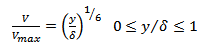 | (11) |
Where Vmax is the free-stream velocity; y is the transverse coordinate originating at the pseudo-bottom and δ is the boundary layer thickness defined as the perpendicular distance from the pseudo-bottom to the point where the velocity is 0.99 Vmax.
4. Conclusions
The hydraulic performance of the stepped spillway is the capability to dissipate more energy than smooth spillways because of the large value of surface roughness.In high velocity flows on stepped channel, air is entrained at the free surface, is caused by the turbulent velocity acting next to the air-water interface. In the skimming flow regime and upstream of the inception point, the flow is smooth and glassy, when the outer edge of the growing boundary layer reaches the free surface, air entrainment starts. Downstream of the inception point the flow becomes uniform as the depth of the air-water mixture grows.In the present numerical study, flow over flat sloped stepped spillway was simulated by using fluent. Free surface was treated by VOF model and turbulence flow was estimated by k-ε Standard Model. Good agreement is found between numerical and experimental results. It was found that the inception point moves toward the basin floor when the discharge increases. This study proved that the formula developed by Chanson[5] can be used to determine the location of the inception point on stepped chute with Froude surface roughness (F*) ranging from 10 to 100. The velocity profile compared favourably with the one sixth power law distribution near the inception point. Minimum and maximum pressure is located in the vertical and horizontal face of step. Lastly, the findings from this research are an indication that the FLUENT software is powerful tool to simulate the air-water flow and to help in the design of stepped spillway together with the physical model.
References
| [1] | Afshin Eghbalzadeh and Mitra Javan, 2012, Comparison of Mixture and VOF Models for Numerical Simulation of Air–entrainment in Skimming Flow over Stepped Spillways .J. of Science Direct. Procedia engineering (28) 657 – 66. |
| [2] | Benmamar,S. Kettab, A. and Thirriot, C., 2003, Numerical simulation of turbulent flow upstream of the inception point in a stepped channel. Proceedings,30th IAHR Congress. Auth, Thessaloniki, Greece: 679-686. |
| [3] | Boes, R. M. and W. H. Hager, 2003, Two-phase flow characteristics of stepped spillways. Journal of Hydraulic Engineering, ASCE, 129(9):661-670. |
| [4] | Bombardelli FA, Meireles I, Matos J, 2010, Laboratory measurements and multi-block numerical simulations of the mean flow and turbulence in the non-aerated skimming flow region of steep stepped spillways. Environ. Fluid Mech 11(3):263-288. |
| [5] | Chanson, H, 1994, Hydraulics of skimming flows over stepped channels and spillways. IAHR, J. Hydr. Res. 32(3):445-460. |
| [6] | Chanson. H, 1997, Air Bubble Entrainment in Free-Surface Turbulent Shear Flows. Academic Press, London, UK, 401 pages ISBN 0-12-168110-6. |
| [7] | Chanson, H. 2000 Characteristics of skimming flow over stepped spillways: Discussion. Journal of Hydraulic Engineering, ASCE 125(4): 862‐865. |
| [8] | Chanson, H., 2002, The Hydraulics of Stepped Chutes and Spillways. Steenwijk, the Netherlands: A. A. Balkema Publishers. |
| [9] | Charles E.Rice and Kem C.Kadavy, 1996, Model of A roller compacted concrete stepped spillway. Journal of Hydraulic Engineering, ASCE, 122(6):292-297. |
| [10] | Chen, Q., G.Q. Dai and H.W. Liu., 2002, Volume of Fluid Model for Turbulence Numerical Simulation of Stepped Spillway Over Flow. Journal of Hydraulic Engineering, ASCE 128 (7): 683-688. |
| [11] | Christodoulou,G.C. 1993, Energy dissipation on stepped spillways. Journal of Hydraulic Engineering, ASCE 119 (5): 644-650. |
| [12] | Fluent, 2006, Manuel and user guide, Fluent Inc |
| [13] | Hunt SL, Kadavy KC., 2009, Inception point relationships for flat-slopped stepped spillways. ASABE Annual international meeting. Reno, Nevada. |
| [14] | Hunt, S. L., and K. C. Kadavy., 2010, Energy dissipation on flat-sloped stepped spillways: Part 1. Upstream of the inception point. Trans. ASABE 53(1): 103-109. |
| [15] | Iman Naderi Rad and Mehdi Teimouri., 2010, An Investigation of Flow Energy Dissipation in Simple Stepped Spillways by Numerical Model. European Journal of Scientific Research. ISSN 1450-216X Vol.47 No.4:544-553. |
| [16] | Rajaratnam, N, 1990, Skimming flow in stepped spillways. Journal of Hydraulic Engineering, ASCE 116 (4): 587-591. |
| [17] | Wood, I. R., P. Ackers, and J. Loveless., 1983, General method for critical point on spillways. Journal of Hydraulic Engineering ASCE, 109(2):308-312 |
 Abstract
 Reference
 Full-Text PDF
 Full-text HTML