-
Paper Information
- Next Paper
- Paper Submission
-
Journal Information
- About This Journal
- Editorial Board
- Current Issue
- Archive
- Author Guidelines
- Contact Us
International Journal of Hydraulic Engineering
p-ISSN: 2169-9771 e-ISSN: 2169-9801
2013; 2(1): 1-13
doi:10.5923/j.ijhe.20130201.01
Prediction of Scour Downstream Regulators Using ANNs
 Abstract
 Reference
 Full-Text PDF
 Full-text HTML
Bakhiet Shenouda 1, Gamal Abouzeid Abdel-Rahim 2, ALI K. A. 3, Norihiro Izumi 4
1Laboratory of River and Watershed Engineering, Nishi 8, Kita 13, Kita-ku, Sapporo, Hokkaido, 060-8628, Japan. Assistant lecturer, Aswan Faculty of Engineering, Aswan University, Egypt
2Professor of Hydraulics, and Water structures, Assiut University, 71516, Egypt
3Dept., of Civil Engineering, Aswan Faculty of Engineering, Aswan University,81542 Egypt
4Department of Civil Engineering, Hokkaido University, Nishi 8, Kita 13, Kita-ku, Sapporo, Hokkaido, 060-8628, Japan
Correspondence to: Bakhiet Shenouda , Laboratory of River and Watershed Engineering, Nishi 8, Kita 13, Kita-ku, Sapporo, Hokkaido, 060-8628, Japan. Assistant lecturer, Aswan Faculty of Engineering, Aswan University, Egypt.
| Email: |  |
Copyright © 2012 Scientific & Academic Publishing. All Rights Reserved.
Regulators is considered one of the main irrigation structures that is used for many purposes. One of the main purposes of regulators is to measure and control the discharge of rivers; also it is used to control the water levels and to generate power. Scour is an inevitable problem that occurs downstream regulators. Different researchers tried to predict scour hole downstream regulators, but their results always gave scour dimensions less than that actually occur. Scour was studied either on solid bed by means of velocity distribution or on movable bed by investigating the topography of the scour hole. In this paper, the scour hole was studied on movable bed by using a new technique rather than the traditional techniques used by other researchers. Due to the complex and unexpected behaviour of water as well as sediment movement downstream regulators, a Back-Propagation Neural Network (BPN) model was developed to predict the dimensions of the scour hole formed downstream regulators, in order to overcome the problem of exclusive and non-linear relationships. A Three layered feed forward neural network using Levenberg-Marquardt algorithm was formulated. The inputs to the (BPN) model were obtained through an extensive experimental program carried out on a trapezoidal channel 0.0001 bed slope. The study covers free and submerged hydraulic jump conditions in both symmetrical and asymmetrical under-gated regulations. It was found that the scour hole dimensions in case of submerged hydraulic jump is always greater than the free one, also the scour hole dimensions in asymmetrical operation is greater than symmetrical one. From the comparison between the experimental results and the predicted ones by the (BPN) model, we found that the scour hole dimensions can be efficiently predicted using (BPN).
Keywords: Back-propagation Neural Network (BPN), Prediction Models, Regulators, Scour
Cite this paper: Bakhiet Shenouda , Gamal Abouzeid Abdel-Rahim , ALI K. A. , Norihiro Izumi , Prediction of Scour Downstream Regulators Using ANNs, International Journal of Hydraulic Engineering, Vol. 2 No. 1, 2013, pp. 1-13. doi: 10.5923/j.ijhe.20130201.01.
Article Outline
1. Introduction
- Most of the existing hydraulic structures such as regulators consist of multi-vents and most problems that occur downstream of such structures are due to the wrong operation of the multi-vents leading to unpredicted velocity distribution which in turn leads to unexpected scour patterns. Due to the existence of piers and abutments as parts of these structures, the flow issuing out of their gates behaves as flow in sudden expanding stilling basin when all gates are working together. Mostly, symmetric flow in sudden expanding stilling basins resulted in symmetric scour downstream of the basin and vice versa[1],[2]. The study of scour hole downstream control structures was studied either by velocity distribution or by investigating the topography of the scour hole on movable bed located after an arbitrary length of rigid floor. Velocity distribution over rigid bed upstream of the movable bed helps in depicting the nature of scour patterns downstream of the rigid bed. Studies on velocity distribution downstream of single vent regulatorsmay be found in[3],[4]. Studies of local scour of alluvial channels near rigid aprons which are based upon the examination of topography of scour holes produced by different hydraulic conditions was studied by different researchers among them[5],[6]. The flow downstream irrigation structures may be free or submerged; however, the submerged flow is the mostly encountered in the field. Many studies are available in the literature about the submerged flow and submerged hydraulic jump characteristics under numerous flow conditions[7]–[13]. Most of these investigations concluded that the length of the roller of submerged hydraulic jump is longer than that of free one; consequently the scour length may be largely extended in case of submerged hydraulic jump rather than free one. Attempts to verify these results were investigated in this study.The study of scour downstream irrigation structures using (ANNs) was studied by many researchers. The underlying reason for the overall superiority of the (ANNs) models to the existing and the proposed formulas is attributed to its ability to capture the highly non-linear relations among the different parameters. Application of (ANNs) in the field of Hydraulic and Water Engineering could be found in[14]–[17]. Applications of (ANNs) to predict scour downstream hydraulic structures such as culvert is presented by[18] and to predict scour at bridge abutment was presented by[19]. Prediction of hydraulic jump characteristics using (ANNs) was introduced by[14],[20]. Application of (ANNs) to predict discharge below sluice gates under free and submerged flow was investigated by[21], and to predict discharge below gate with sill[22]. Detailed information on the subject of (ANNs) may be found in[23]. The aforementioned methods do not give a reliable formula to predict scour hole dimensions downstream regulators to cover all possible ranges, where all formulae obtained from the previous studies give scour hole dimensions less than the actual one. A new technique was introduced in this paper to study the scour hole dimensions downstream hydraulic structures over movable bed both experimentally and theoretically, where all the previous studies on movable bed, predict the scour length by assuming an arbitrary length of rigid apron L, less than the expected scour length, Ls, and they consider that the length of the scour hole Ls, is equal to the length of the rigid floor plus the length of the scour hole formed in the downstream;
 . Actually, this technique gives smaller scour lengths than the actual ones.This paper solves that problem by extending the arbitrary length of the rigid floor, L by the same value of the length of the scour hole Xs formed in the downstream until no scour hole is allowed to form. For this purpose, three millimetres steel sheets with the same channel width and different lengths according to the length of the scour hole Xs, were used to extend the rigid apron length behind the model of the regulators. The study covers different flow scenarios that might occur in the field, where free and submerged hydraulic jumps were investigated, and also both symmetrical and asymmetrical operations were taken into consideration. Based on the previous obtained data from the experimental program, a (BPN) model was created to predict the scour hole dimensions downstream 3-vents regulators. The model is a three layered feed forward neural network which uses Levenberg-Marquardt algorithm. An optimization technique was investigated to the (BPN) model to obtain the perfect prediction model for simulating the scour process. Trial and error method was used to obtain the best network parameters for the best performance of the model. The results of the (BPN) model showed a good agreement with the experimental results with high correlation coefficient.The study reveals that the minimum length of rigid apron to prevent scour Ls is always greater than the sum of the lengths of the arbitrary rigid apron and that of scour hole formed behind it; (L+Xs) for the same flow conditions. Also the scour hole dimensions is found to be greater in case of submerged hydraulic jump than free one, furthermore the dimensions increase in case of asymmetrical operation than symmetrical one.
2. Dimensional Analysis
 | Figure 1. Definition sketch showing the geometry of the scour hole and the different parameters considered in this study |
 | Figure 2. Different parts of the experimental channel |
 | (1) |
 | (2) |
 | (3) |
 is the Froude number,
  is the Reynolds’ number,
  is the shields parameter,
  is the bed shear stress calculated at the separation point between the solid floor and the sand basin, it may be given as[24]:
 | (4) |
 is the friction coefficient obtained from the following formula[24];
 | (5) |
 , is the critical shear stress obtained from shields’ diagram[26], it may be calculated from the following formula:
 | (6) |
 , is the specific weight of soil particles,
  is the specific weight of water and
  is a parameter ranges from 0.04 to 0.1[26].In free surface model studies, the viscous force does not affect the flow field and therefore Re, in (3) may be dropped[27],[28]. In open channel flow[29] found that the gravity starts to affect the flow resistance when Fe equals to 2.49.Reference[30] revealed that the importance of Froude number appears only when roll waves develop to form a state of unstable flow. Hence, (3) reduces to;
 | (7) |
3. Materials and Methods
3.1. Channel
- The investigations reported herein were conducted in a sloped-bed channel of trapezoidal cross section as shown in Fig. 2. Generally the channel has a bed width of 0.84 m and a depth of 0.6 m. It consists of four parts, the first part is trapezoidal with side slope 1:1 and total length of 4.00m, the second part is rectangular which has a length of 1.50 m. This part is the testing section where the model of regulators was installed in it. The third part is trapezoidal with side slopes 1:1 and length of 3.00 m. In this part sand with 0.502 mm diameter was placed with a depth of 20 cm. The fourth part has a trapezoidal cross section with side slopes 1:1 and a sufficient length of 10.00 m to create a uniform flow in the downstream. The uniform water flow depth could be adapted by means of a tailgate installed at the channel end. The flow rate was regulated by a gate valve located on the feeding pipeline and was measured by a calibrated V-notch. Water depths and bed levels were measured by point-gauges. The velocity was measured by a calibrated Pitot-tube.
3.2. Model
- Three sluice gates and two intermediate piers were formed a model of three-vents regulator as shown in Fig. 2. Each gate has 0.24 m width, 0.60 m height and 6 mm thickness with sharp edge. The pier is 60 mm in width, 0.60 m total length, 0.38 m of them behind the gates and it has two 7x8 mm groves to hold the gates in a vertical position. The gates can be lifted and lowered to give the desired under-gated opening height that permits to form free or submerged hydraulic jump conditions on the solid bed.
3.3. Experimental Method
- The experimental program which was carried out to investigate the scour hole dimensions downstream regulators under different flow conditions was divided into two categories:i. First category: In this category, the experiments were performed to determine the total length of the scour hole as the previous studies, where the length of the scour hole equal to the sum of the arbitrary length of the solid floor and the length of scour hole formed in the downstream (L+Xs). The experimental procedures were as follows:1)- The three gates were lifted up to give a certain opening-height, h (case of symmetrical regulation).2)- The downstream portion of the channel was filled with water to a certain limit.3)- The run started with low flow rate, and then gradually the flow rate was increased to the required one.4)- The downstream water depth was adjusted by the tail gate till the formation of free hydraulic jump just behind the gates and between the piers (case of free jump) or the formation of a submerged hydraulic jump between the piers (case of submerged jump) with maximum upstream water depth Y1 not more than 2.2 times the downstream water depth Y2[31].5)- After 4 hours run time[32], the water depths upstream Y1 and downstream the gates Y2, the discharge Q, and the velocity near the bed at the end of rigid floor were recorded. Then the flow was stopped and the scour hole length Xs and its depth ds were measured.6)- The gates opening or the discharge was changed and the procedures from 1 to 5 were repeated.7)- For asymmetric flow, the left hand side vent of the model of the regulator was closed and the same procedures from 1 to 6 were repeated.ii. Second category: In this category, tests were performed to find out the minimum scour length where no tail erosion is encountered on the erodible basin. Three millimeters steel sheets with 0.84 m wide and different lengths were used to extend the rigid apron length behind the model of the regulator as shown in Fig. 3.
 | Figure 3. Definition sketch showing the technique used to extend the rigid floor to prevent the formation of the scour hole |
 | (8) |
 , represents the summation of all possible lengths that can be added to the arbitrary length of the rigid floor to prevent scour. The test procedures in this case were as follows:1)- In symmetrical case and for both the formation of free or submerged hydraulic jump downstream the gates of the regulator, the discharge Q, downstream water depth Y2, and consequently upstream water depth Y1 were chosen.2)- The rigid apron length behind the model was extended gradually; the recorded erosion rate was decreasing till there was no erosion encountered. Then, the minimum length of rigid apron measured from the end of the gates to the beginning of the erodible bed Ls was recorded to the nearest 10 mm. At this moment the velocity near the bed at the end of rigid apron was measured.3)- The gates opening or the discharge was changed, and then steps 1 and 2 were repeated.4)- For case of asymmetrical under-gated regulation, the left hand side vent of the model of the regulator was closed and same procedures from 1 to 3 were repeated.
 3.4. Back-Propagation Neural Network Model (BPN)
- A typical three-layered neural network with an input layer (I), a hidden layer (H) and an output layer (O), Fig. 4 is adopted in this study. Each layer consists of several neurons and the layers are interconnected by sets of correlation weights. The neurons receive inputs from the initial inputs or from the interconnections and produce output by the transformation using an adequate non-linear transfer function in the hidden layer and linear function in the output layer. The transfer functions used in this research are the sigmoid transfer function in the hidden layer expressed by
 , it has a characteristics of
  and the purelin transfer function in the output layer. The training process of a neural network is essentially executed through a series of patterns. In the learning process, the interconnecting weights are adjusted within input and output values. The model parameters were optimized by Levenberg and Marquardt algorithm, which is one of the most common and successful back-propagation algorithms. To make the algorithm fast and easy to learn the non-linearity between the inputs and outputs, it is important to use some processing functions with the inputs as well as the outputs. These processing functions are built-in functions in MATLAB’s Neural Network Toolbox. A MATLAB’s processing functions were applied to normalize the input and output values, which is a requirement ofLevenberg–Marquardt back-propagation algorithm calculation process for (ANNs) modeling.
 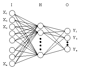 | Figure 4. Structure of an artificial neural network |
 in all possible cases (free, submerged, symmetrical, and asymmetrical case), on the other hand, the output from the model will be the dimensionless minimum length of rigid apron downstream the gates to prevent scour
  , the dimensionless summation of the lengths of rigid apron and that of scour hole formed behind it
  and the dimensionless scour hole depth
  .The (BPN) is the most representative learning model for the artificial neural network. The procedure of the BPN is that the error at the output layer propagates backward to the input layer through the hidden layer in the network to obtain the final desired outputs. The gradient descent method is utilized to calculate the weights of the network and to adjust the weights of interconnections to minimize the output error. The error function at the output neuron is the least mean square (LMS) error function defined as:
 | (9) |
 | (10) |
 is the learning rate and the general form of the
  term is expressed by the following form:
 | (11) |
 | (12) |
 is the output value of sub-layer related to the connective weight
  and
and  is the error signal, which is computed based on whether or not neuron
  is in the output layer. If neuron
  is one of the output neurons, then:
 | (13) |
 | (14) |
 is the value of the hidden layer.Finally, the value of weight of inter-connective neuron can be expressed as:
  | (15) |
 is included into (15).
 | (16) |
 | (17) |
 is the observed value,
  is the predicted value,
  is the mean value of predictions,
  is the mean value of observations and n is the number of data points.The previous steps which was performed to obtain the most appropriate (BPN) model is shown summarized in the flow chart in Fig. 5.
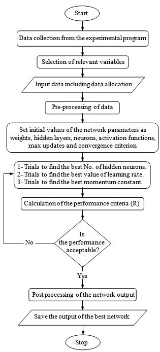 | Figure 5. Flowchart showing the basic steps of building the (BPN) model for the present study |
4. Application and Discussion of Results
4.1. Data Analysis Based on the Experimental Point of View
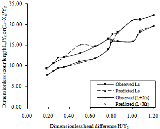
- Most investigations on local scour of alluvial channels near rigid aprons were based upon the examination of the topography of scour holes produced by different hydraulic conditions[33]–[36]. In the present study, another approach is considered, where the scour reach will be represented by both the minimum floor length Ls to prevent scour behind the model of three vents regulator or by the sum of an arbitrary length (L < Ls) besides the length of scour hole Xs. For this reason the analysis of the scour length in the following sections will be represented either by Ls or by (L + Xs). At first, it is important to perform a preliminary check for the experimental results to take decision about the case (free or submerged case) that will be used as an input to the (BPN) model. Fig. 6 indicates the relationship between the dimensionless head difference, H/Y2, and the dimensionless scour length Ls/Y2 or (L+Xs)/Y2 for the free and submerged cases.
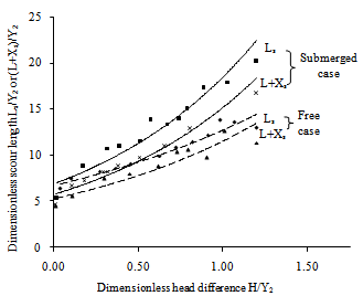 | Figure 6. Variation of Ls/Y2 or (L+Xs)/Y2 with H/Y2 for free and submerged under-gated regulations (symmetrical case) |
 | (18) |
 | (19) |
 | (20) |
 | (21) |
 | (22) |
 | (23) |
 | (24) |
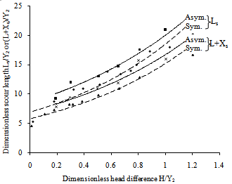 | Figure 7. Variation of Ls/Y2 or (L+Xs)/Y2 with H/Y2 for symmetrical and asymmetrical under-gated regulations (submerged case) |
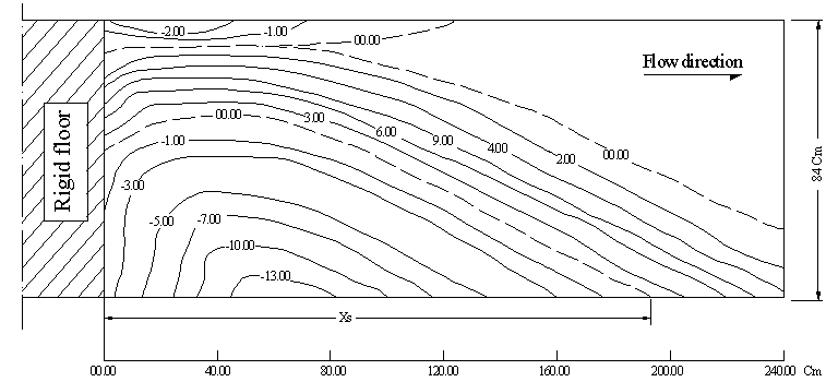
 | Figure 8. Contour lines of the movable bed showing the scour hole profile behind the rigid floor of length, L = 0.60 m for symmetrical under-gated regulation (H = 0.16 m, Q = 21 Lit./s and hg =32mm) |
 | Figure 9. Contour lines of the movable bed showing the scour hole profile behind rigid floor of length, L = 0.60 m for asymmetrical under-gated regulation (H = 0.16, Q = 21 Lit./s and hg =43mm) |
4.2. Determination of the Optimized (BPN) Prediction Model
- To predict scour hole dimensions in all possible cases that have been mentioned earlier, an optimization procedures were implemented to illustrate the applicability of the (BPN) model with different structures to tide predictions. A (BPN) used here is a non-linear system in which parameters affect each other. This section discusses how the neural network structure affects the performance of the forecasting model, which includes the number of neurons in the hidden layer n, the learning rate
 , and the momentum constant
  . The number of the training iterations (Epochs) will be kept constant at 1000 iterations. The input and output pairs of data to the (BPN) model were divided randomly using a suitable function, where we customize the divide process between the training data sets (70%) and test or validation data sets (30%). Several results have been obtained, but we chose the trial which gave high correlation coefficient especially in the test data test, because these data represents the testing of new data to the network that has never seen before.The number of neurons in the hidden layer was selected to vary from 2 to 16 with a constant step of 2 neurons. Table 1 shows the values of correlation coefficient for various neurons structures with constant learning rate of 0.05, constant momentum of 0.4 and constant epochs of 1000. It shows that the quality of simulations improved when the number of neurons is 6 neurons. Thus, the number of neurons in the hidden layer is recommended to be 6 neurons because of its satisfactory prediction performance, where the correlation coefficient for all and test data sets equal to 0.9873 and 0.9702 respectively.
 will significantly affect the convergence of neural network learning algorithm, so it is recommended to try different values of the learning rate. Table 2 indicates the different values of the correlation coefficient with the optimum number of neurons obtained from the previous step, (n = 6) with variable learning rate. It is clear that the suitable learning rate is 0.05 with the optimum 6 neurons obtained from the previous step.
| |||||||||||||||||||||||||||||||||||||||||||||||||||||
 may accelerate the convergence of the training process, so it is preferable to change the momentum constant to obtain the most suitable (BPN) prediction model. Table 3, shows the different momentum values that have been used in this study to obtain the perfect (BPN) model. It indicates that the efficiency of the model is better when the momentum constant is equal to 0.7, where the best performance is achieved with a correlation coefficient of 0.9886 for all data sets and 0.9836 for test data set.
| |||||||||||||||||||||||||||||||||||||||||||||||||||||
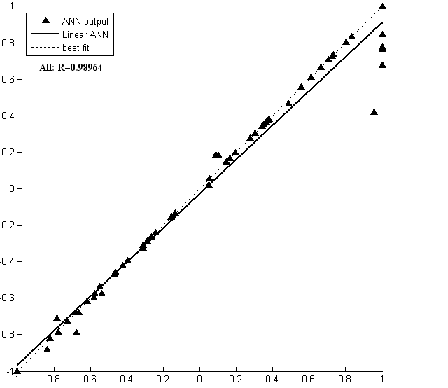 | Figure 10. The BPN model predictions for all data sets |
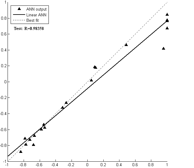 | Figure 11. The BPN model predictions for test data sets |
4.3. Scour Predictions in Case of Symmetrical Operation
- The results of the optimum (BPN) model, obtained earlier with 6 neurons in the hidden layer, learning rate of 0.05 and momentum constant of 0.7, were used to predict the scour hole length in case of symmetrical operation. Shown in Fig. 12, the relation between the dimensionless scour length Ls/Y2 or (L+Xs)/Y2 and the dimensionless acting head H/Y2.
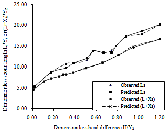 | Figure 12. Comparison between the forecasting results of the BPN model and that of experimental observations for the influence of the head difference on the scour length Ls or (L+Xs) |
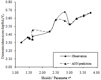 | Figure 13. Comparison between the forecasting results of the BPN model and that of experimental observations for the influence of bed shear stress on the scour depth formed downstream rigid apron having length (L) |
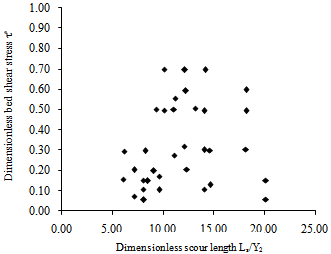 | Figure 14. Variation of Ls/Y2 with the values of τ* |
4.4. Scour Predictions in Case of Asymmetrical Operation
- In the field the operation of regulator may be asymmetrical under-gated regulation especially at the maintenance period, where the emergency gates are closed. For this reason it is practical to investigate the effect of the asymmetrical operation on the scour length behind the regulators. The relation between the dimensionless head difference H/Y2 and the dimensionless scour length Ls/Y2 or (L+Xs)/Y2 is shown plotted in Fig. 16.
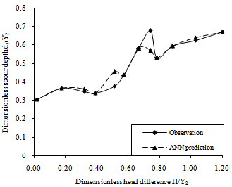 | Figure 15. Comparison between the forecasting results of the BPN model and that of experimental observations for the influence of the head difference on the scour depth formed downstream rigid apron having length (L) |
 | Figure 16. Comparison between the forecasting results of the BPN model and that of experimental observations for the influence of the head difference on the scour length (Ls) |
4.5. Comparison between the Results Obtained from this Study and Other Studies
- Moreover the present results on Ls are depicted in Fig. 17 showing the variation of Ls/Y2 against H/Y2 in comparison with other researchers[39] and different regulators or barrages on the Nile River in Egypt.Apparently, the scour length obtained from the movable bed presented herein is found to be about 3.6 times that predicted from the velocity distribution method presented by[39]. This means that the erosion depends on the amount of turbulence which is not represented by the direct measurements of the velocity distributions.The data in Fig. 17 are quoted from[24]. The scour reaches of Assiut and old Esna barrages have been taken after the recent remodelling of these structures for the protection against the tail erosion noticed downstream of the rigid floor[24]. We can see that the present results of scour length Ls are in agreement with the existing ones for the mentioned structures.
5. Conclusions
- Accurate predictions of scour depth and length downstream control structures such as regulators are essential for the stability of the structure. This article has introduced the problem of scour downstream regulators from both the experimental and theoretical point of views. Furthermore we introduced a new technique for studying the scour hole over movable bed. The study was performed under different flow scenarios, where free, submerged, symmetrical and asymmetrical conditions have been examined to try to cover all possible cases that might occur in the field. Prediction (BPN) model has been implemented to try to study the scour phenomenon using (ANNs). The following conclusions could be derived from this research:1)- Artificial Neural Networks is very efficient tool to predict the dimensions of the scour hole, where we can avoid expensive and time consuming hydraulic model studies for various flow scenarios. Meanwhile it can predict the non-linear relationships between inputs and outputs with high correlation coefficient.2)- The observed and the predicted values of scour depth showed the efficiency of the model to predict scour depth and length in all possible cases, where the correlation coefficient was 0.9886 for all data sets and 0.9836 for test data set for the best prediction (BPN) model. 3)- Scour hole dimensions increase in case of submerged under-gated regulations in comparison to free case. 4)- The minimum scour hole length, Ls with no scour hole allowed, is found to be longer than the length of the arbitrary length of the rigid floor, L plus the length of the scour hole Xs, formed downstream the model, (L+Xs).5)- Asymmetrical under-gated regulation is not recommended as a working regulation otherwise its effect must be taken into consideration during design process or it can be scheduled in case of low discharge periods.
Symboles
- The following symbols are used in this paper: Output value of the sub-layer, ds: Maximum scour depth,d50: Mean particle diameter of bed material, E: error value
 : Friction coefficient, Fe: Froude number, g :Acceleration of gravity,H: Head difference between upstream and downstream water levels,L: Arbitrary length of rigid apron behind the gates (L
 : Connective weight between input and hidden layers,Xs: Length of scour hole, Y: (BPN) output, Y1: Upstream water depth,Y2: Downstream water depth,
 : Momentum constant, γs :Specific weight of soil particles,γw :Specific weight of water,
  : Error signal of the neuron,
 : Parameter,
  : Learning rate of the (BPN),μ :Dynamic viscosity, ρ :Water density, ρs :Soil particles density,τb :Bed shear stress, and; τc :Critical shear stress.
References
| [1] | Negm, A.M., Abdel Aal, G.M., Saleh, O.K., and Sauida, M.F., “Effect of supercritical flow on scour characteristics downstream of sudden expanding stilling basin”, EJEST Journal, Faculty of Engineering, Zagazig University, Vol. 6, No. 1, January, 2002, pp. 129-141. |
| [2] | Negm, A.M., Saleh, O.K., Abdel-Aal, G.M. & Sauida, M.F., “Investigating scour characteristics downstream of abruptly enlarged stilling basins”, Proceedings of the International Conference on Fluvial Hydraulics, River Flow 2002, Sep. 1-4, Belgium, Published by D. Bousmar & Y. Zech, Editors, Swets & Zeitlinger, Lisse, The Netherlands, 2002, (ISBN 90-5809-509-6). |
| [3] | Saleh, O.K., “River training and protection for reach downstream of hydraulic structures”, Ph.D. Thesis, Submitted to Faculty of Engineering, Zagazig University, Zagazig, Egypt, 1995. |
| [4] | Saleh O. K., “Velocity distribution downstream hydraulic jump”, Engineering Research Journal, Vol. 62, April, Faculty of Engineering, Helwan University, Mataria, Cairo, Egypt, 1999, pp.103-114. |
| [5] | Hemaid, H.S.,” Bed erosion at submarine pipelines exposed to unidirectional water flow”, M. Sc. Thesis, Civil Eng. Dept., Assiut Univ., Egypt, 2000. |
| [6] | Youssef, H.,” Anew analytical bridge pier scour equation”, Proc. Of 8th Int. Water Tech. Conf. (IWTC), Alex., Egypt, 2004. |
| [7] | Govinda Rao, N.S. and Rajaratnam, N., “The submerged hydraulic jump”, Journal of Hydraulic Div., Vol. 89, No. HY1, 1963, pp. 139-163. |
| [8] | Rajaratnam, N., “Submerged hydraulic jump”, Journal of the Hydraulic Div., Vol. 91, No. HY4, 1965, pp. 71-96. |
| [9] | Rajaratnam, N., “Hydraulic jump in advances in hydro-science”, Vol. 14 Edited by V.T. Chow, Academic Press, New York and London, 1967, pp. 197-280. |
| [10] | Rajaratnam, N., “Erosion by submerged circular jets” Journal of the Hydraulic Division, Vol. 108, No. HY2, February, 1982, pp. 262-267. |
| [11] | Narasimhan, S., and Bhargara P., “Pressure fluctuations in submerged jump”, Journal of the Hydraulic Div., Vol. 102, No. HY3, 1976, pp. 339 350. |
| [12] | Abdel Alal, G.M., “Modeling of Rectangular Submerged Hydraulic Jumps”, Alexandria Engineering Journal, Vol. 43, No. 6, 2004, pp.865-873. |
| [13] | Negm, A.M., Abdel-Aal, G.M., Elfiky, M.I., and Mohmed, Y.A., “Characteristics of submerged hydraulic jump in radial basins with a vertical drop in the bed”, AEJ, Faculty of Eng., Alexandria University, Egypt, 2002. |
| [14] | Negm, A.M., “Prediction of hydraulic design parameters of expanding stilling basins using artificial neural networks”, Egyptian Journal of Engineering Science and Technology, EJEST, Oct., Vol.5, No.2, 2002, pp. 1-24. |
| [15] | Dibike, Y.B., Solomatine, D. and Abbott, M.B., “On the encapsulation of numerical-hydraulic models in artificial neural network”, J. Hydraulic Research, Vol.37, No.2, 1999a, pp.147-162. |
| [16] | Dibike, Y.B. and Abbott, M.B., “Application of artificial neural networks to the simulation of a two dimensional flow”, J. Hydraulic Research, Vol. 37, No.4, 1999b, pp.435-446. |
| [17] | Dibike, Y.B., Minns, A.W. and Abbott, M.B., “Applications of artificial neural networks to the generation of wave equations from hydraulic data”, J. Hydraulic Research, Vol. 37, No. 1, pp. 81-97, Discussion Vol. 38, No.4, 2000, 1999c, pp.317-318. |
| [18] | Liriano, S.L. and Day, R.A., “Prediction of scour depth at culvert outlets using neural networks”, Journal of Hydroinformatics, Vol. 03, No. 4, Oct., 2001. |
| [19] | Kheireldin, K.A., “Neural network modeling for clear water scour around bridge abutments”, Water Science, Scientific Journal of National Water Research Center, MWRI, El-Qanatir, Egypt, Vol. 25, April, 1999, pp.42-51. |
| [20] | Negm, A.M. and Shouman, M.A., “Artificial neural network model for submerged hydraulic jump over roughened floor”, Proc. 2nd Int. Conf. For Advanced Trends in Engineering (MICATE’2002), April 7-9, Faculty of Engineering, Al-Minai University, Egypt, 2002. |
| [21] | Negm, A.M., Saleh, O.K. and Ibrahim, A.A., “Application of artificial neural networks to predict flow rates below vertical sluice gates”, Engineering Research Journal, Faculty of Engineering, Hellwan University, Mataria, Cairo, Egypt, Vol. 70, Feb., 2002a. |
| [22] | Negm, A.M., "Generalized silled-sluice-gate discharge ann model in prismatic rectangular channels”, Proc. 2nd Int. Conf. For Advanced Trends in Engineering (MICATE’2002), April, 7-9, Faculty of Engineering, Al-Minai University, Egypt, 2002. |
| [23] | Schalkoff, R.J., “Artificial neural networks”, Computer Science Series, McGraw-Hill Co., Inc., New York, 1997. |
| [24] | Ali, N.A.,” The proper location of floor sill with scour reach downstream of heading-up structure”, Jour. Of Eng. Scie. (JES), Faculty of Eng. Assiut Univ., 23(2), July 1995. |
| [25] | Yassin, A.M.,” Design of irrigation structures (2)”, Lec. Note, Civil Eng. Dept., Assiut Univ. 1984. |
| [26] | Leliavesky, S.,” An introduction to fluvial hydraulics”, Constable & Company LTD., London, 1955. |
| [27] | Ali, N. A.,” A contribution to sediment transportation with reference to hydraulic resistance”, M. Sc. Thesis, Civil Eng. Dept. Assiut Univ., 1978. |
| [28] | Khalil, M. B.,” Hydraulic roughness of channels with rippled-bed”, Bulletin of Science & Tech., Assiut Univ., 1969. |
| [29] | Powel,R.W.,”Flow in channel of definite roughness”, Trans., ASCE, (111), 1946. |
| [30] | Rouse, H.,” Critical analysis of open channel resistance”, J. of Hyd. Div., ASCE, Vol. 91 No. HY.4, July 1965. |
| [31] | Ismail, H. and Shalasdh, M. S.,”Study of scour below hydraulicstructures by means of velocity distribution”, Bulletin of Faculty of Eng., Cairo Univ., 1954. |
| [32] | Grade, R. J., Subramabya, K., and Nambudrpad, K. D., “Study of Scour Around Spur Dikes”, J. Hyd. Div., ASCE, 87(6), 1961. |
| [33] | Ali, N.A.,” Scour prediction at submarine pipelined near the sea bed”, Bulletin of Faculty of Eng., Assiut Univ. 24(1), Jan. 1996. |
| [34] | Hassan, M.K.,” Erosion of alluvial bed downstream of a sluice gate”, Ph. D. thesis, Dept of Civil and Structural Eng. (UMIST), U.K. 1985. |
| [35] | Kamil, H.M., and Karim O.,” Simulation of flow around piers”, J. Hydr. Res.(IAHR), 40(2), 2002. |
| [36] | Roudkivi, A.J., and Ettema, R.” Clear-water scour at cylindrical piers”, Jour. Of Hyd. Eng., 109(3), March 1983. |
| [37] | Chatterjee, S.S., and Ghosh, S.N.,” Submerged horizontal jet over erodible bed”, Jour. Of Hyd. Div., ASCE, 106(HY), Nov. 1980. |
| [38] | Bligh, W.G.,” The practical design of irrigation works”, Constable, 2nd edn., London, 1912, found in Ref.[1]. |
| [39] | El-Dardeer, M.,”Different ways of passing water through the gates of regulators and its effect on scour below”, M. Sc. Thesis, Civil Eng. Dept., Assiut Univ., Egypt, 1986. |