-
Paper Information
- Paper Submission
-
Journal Information
- About This Journal
- Editorial Board
- Current Issue
- Archive
- Author Guidelines
- Contact Us
International Journal of Hydraulic Engineering
2012; 1(4): 25-31
doi: 10.5923/j.ijhe.20120104.01
Water Leakage through a Small Opening
 Abstract
 Reference
 Full-Text PDF
 Full-Text HTML
C.-L. Chang , Z. Y. Wu , J. C. Leong
Department of Vehicle Engineering, National Pingtung University of Science and Technology, Taiwan
Correspondence to: J. C. Leong , Department of Vehicle Engineering, National Pingtung University of Science and Technology, Taiwan.
| Email: |  |
Copyright © 2012 Scientific & Academic Publishing. All Rights Reserved.
This paper presents a numerical simulation of a pressurized water leakage through a small opening into an ambient water reservoir. A modified Euler number indicating the relative importance between the forces due to pressure difference and the viscous effect was found good enough to characterize a problem of this nature. The effect of the gap aspect (H/L) ratio was investigated too. Only when the gap aspect ratio is close to unity, the gap flow is found existent in a bi-stable mode. In contrast, the uni-stable mode is possible with the right combination of modified Euler number and gap aspect ratio. More surprisingly, there exists a threshold aspect ratio approximately unity based on this work. Below the threshold aspect ratio, the maximum velocity is only a function of the modified Euler number. However, beyond the threshold aspect ratio, the maximum velocity increases with the gap aspect ratio and the modified Euler number.
Keywords: Leakage Flow, Modified Euler Number, Gap Aspect Ratio, Pressure Gradient
1. Introduction
- The flow behind a gap between two side-by-side bluff bodies has long been studied by Bearman and Wadcock[1], Roshko et al.[2], Zdravkovich[3], Hayashi et al.[4], Kim and Durbin[5] and Miau et al.[6]. If the gap is very small, the flow after the gap demonstrates a bi-stable characteristic. In other words, the flow will stably deflect to either side of the bluff bodies. As the gap increases, the flow goes through a transition from the bi-stable to a uni-stable characteristic. In other words, the steady flow will not deflect to either side of the bluff bodies if the gap is wide enough or, more precisely, the uni-stable characteristic is attained. In the transition, the flow was found flip-flopping between the two bluff bodies in a random manner[5-6].In general, the studies involving this subject were carried out on either cylindrical shapes or flat plates. As one of the pioneering work, Bearman and Wadcock[1] experimentally measured the pressures on two side-by-side circular cylinders at a Reynolds number of 2.5 x 10⁴. Later, Roshko et al.[2] also carried out a similar experiment by measuring the pressure distribution on two triangular cylinders but at a Reynolds number of approximately 2.0 x 10⁴. Both Bearman and Wadcock[1] and Roshko et al.[2] confirmed that the pressure measurements as well as drag coefficients fluctuate between two extreme values when the gap ratio is between 0.1 and 1.0. The gap ratio in these cases was defined as the gap width between the cylinders to the diameter of the cylinders. Years later, Kim and Durbin[5] showed the possibility of controlling the intensity of theflip-flopping flow at a Reynolds number of 3.5 x 10³ and a gap ratio of 0.75 using a splitter plate along the centreline of the gap or acoustic excitations. For flow through the gap between two side-by-side flat plates, Hayashi et al.[4] have found solid evidence, based on their studies corresponding to Reynolds numbers ranging from 0.6 x 10⁴ to 1.9 x 10⁴ and a gap ratio of 1.75, showing that the formation of flip-flopping flow is caused by the formation of shedding vortices trailing the flat plates. For the cases involving flat plate, the definition of gap ratio is similar to the above except replacing the cylinder diameter with the plate thickness. Along the same direction, Miau et al.[6] considered the cases whose gap ratios vary from 1.50 to 1.85 and found that the frequency of flip-flopping flow is proportional to the gap ratio. The problem of fluid seepage through the cracked walls of pressure vessels has been examined quite extensively focusing on the effect of pressure on flow rate[7-10] and the propagation of crack[11-14], but the flow field associated to the opening has not been reported. On the other hand, Wang et al.[15] numerically investigated the patterns of leakage flow through two labyrinth seals. They found that the turbulent kinetic energy reached its maximum at the clearance of the seal. The static pressure dropped rapidly when the fluid flows through the clearance. In the extensive studies mentioned above[1-6], the configuration considered was confined to two bluff bodies placed side-by-side. A stream of flow with a known velocity was forced through the gap in between. With this, the flow phenomena related to Reynolds number and gap ratio were examined closely. Although the possible presence of a flip-flopping flow had made this topic interesting, the authors think that these configurations considered can be extended to cover more engineering applications. In this study, not only does the thickness of the side-by-side flat plates infinitely large but also the length of the gap is considered. In practice, this can be related to a solid wall of a container having a gap though it. If the length of the gap is small, this study simulates the water leakage of a thin wall vessel through a small crack. On the other hand, if the length of the gap is large, this study then simulates the seepage effect associated to a wall with remarkable thickness. For these reasons, it is the pressure difference in this study that drives the flow through the gap. In contrast to the previous studies, a Reynolds number associated to a particular case is unknown. Instead, Reynolds numbers defined based on the maximum velocity within the gap will be estimated for various pressure differences.
2. Formulation
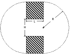
- Figure 1 shows the schematic of the problem. The rectangles connecting to the semicircles on both sides are the solid walls. The gap or opening between these walls is denoted by H. The thickness of the wall (i.e., the length of the gap) is represented by L. The height of these walls is fixed set to be H. Non-slip boundary condition is applied at these walls whereas a prescribed value for pressure is applied along the semicircles. The diameter (= 2R) of these semicircles is arbitrarily chosen as long as their presence will not force unrealistic flow patterns close to the gap. With the given height of the walls and gap width, the diameter of these semicircles is 3H. The only aspect ratio investigated in this study is the one related to the gap or opening which is defined as H/L. In this study, this aspect ratio ranges from 0.2, 0.5, 1.0, 2.0, 5.0, to 10.0.
 | Figure 1. Schematics of the problem |
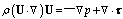
 | (1) |
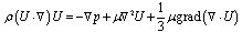
 | (2) |
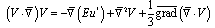
 | (3) |
 | (4) |
 | (5) |
 | (6) |
 | (7) |
 | (8) |
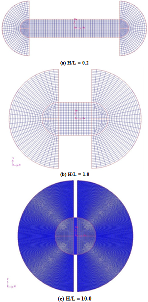 | Figure 2. Distribution of grids for various H/L |
3. Results and Discussions
- The study of a problem involving very fundamental geometries yet significant in terms of engineering applications has been investigated using FLUENT. Since a problem of this fashion has never been investigated before in terms of pressure gradient, it is the responsibility of the present study to examine the feasibility of characterizing this problem using the modified Euler number defined in the previous section. Conventionally, Euler number represents the relative importance between the pressure effect and the inertia effect. In fact, not only is the characteristic velocity scale related to this problem not known at a priory, but also a representative velocity scale is simply not required for problems associated to leakage of highly pressurized tanks. For this reason, a more suitable parameter is proposed in this work. The modified Euler number represents the relative importance between the pressure and viscous effect. A reasonable range of modified Euler number corresponding to practical situations should fall within the order of 108 to 1012. A modified Euler number of 108 can represent water leakage into atmosphere from a tank of 1.3 atm. through a hole of 1 mm. On the other hand, the leakage of a dense fluid from a container is associated a typical modified Euler number in the order of 1012. For instance, water in a tank, whose inner pressure is about 14 atm., leaks into water through a crack of 1 cm wide produces a modified Euler number in the order of 1011. Certainly, as the pressure in the tank or container decreases with time, the corresponding modified Euler number reduces accordingly. Since this work is intended to investigate the steady flow phenomena related to high pressure gradient, current work does not take into consideration of situations of that extreme. Before studying the effects of modified Euler number on the flow patterns, it is perhaps the most important to examine the feasibility and reliability of the modified Euler number and also to ensure its independence of dimensional scale. Figure 3 presents the evidence proving that the approach used in this study is feasible. In Fig. 3(a), H = 0.1 cm whereas in Fig. 3(b) H = 1.0 cm. In order to come out with the same modified Euler number, the pressure in Fig. 3(a) is 100 times greater than that applied in Fig. 3(b). For ease of comparison, the parameters assigned for each case are listed in Table 1. Apparently, the flow patterns for a particular modified Euler number are almost the same regardless of the actual dimensional length scale involved in simulations. In the simulations performed, steady state solutions were assumed attained if the relative errors for two consecutive iterations were less than 10-9. The flow field of most cases skewed either upward or downward even though the geometry is symmetrical. It is remarkable to point out that the gravitational effect is excluded in the calculation. The presence of bi-stable solutions discovered in this work is consistent with what has been reported[1-2]. Hence, the simplification of geometry by assuming an asymmetric boundary condition will lead to incorrect flow distributions for it will always produce a non-biased solution. Obviously, the plausibility of using such an artificial boundary condition requires much more serious thought and justification.
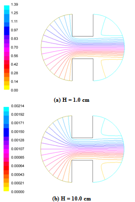 | Figure 3. Distribution of grids for various H/L |
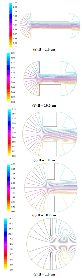 | Figure 4. Distributions of stream function for Eu* = 1010 with various gap aspect ratios |
|
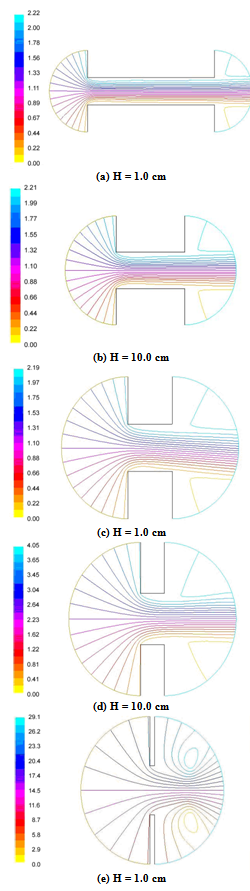 | Figure 5. Distribution of stream functions with H/L = 1.0 but associated to different Eu* |
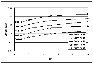 | Figure 6. Variation of maximum velocity with gap aspect ratio for different modified Euler numbers |
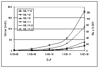 | Figure 7. Variation of maximum velocity with modified Euler number for different aspect ratios |
4. Conclusions
- A numerical simulation of a pressurized fluid flowing through a gap has been successfully performed using FLUENT. It was found that the modified Euler number, defined as the ratio of the force due to pressure difference to the viscous force, is good enough to capture the characteristics of this problem. The flow patterns are almost identical for problems having the same modified Euler number but different dimensions. Also found is that there exists a threshold aspect ratio beyond which the maximum velocity occurred within the flow increases with the gap aspect ratio. If below the threshold aspect ratio, the maximum velocity is independent of the aspect ratio. Based on the present study, the threshold aspect ratio is expected to be approximately unity. Furthermore, the maximum velocity is proportional to the modified Euler number. The proportional constant is found to be a function of the gap aspect ratio if the aspect ratio is greater than the threshold value. Below the threshold aspect ratio, the maximum velocity is merely a function of the modified Euler number. Although this work has only investigated the flow through a gap due to a pressure difference in the laminar regime, it provides result interesting enough for further attentions.
References
| [1] | PW Bearman, AJ Wadcock, "The Interaction between a Pair of Circular Cylinders Normal to a Stream", Journal of Fluid Mechanics, vol. 61, pp. 499-511, 1973. |
| [2] | A Roshko, A Steinolfson, V Chattoorgoon, "Flow Forces on a Cylinder near a Wall or near Another Cylinder", in Proceeding of the 2nd National Wind Conference on Wind Engineering Research, Paper IV-15 , pp. 1–3, 1975. |
| [3] | MM Zdravkovich, "Review of flow interference between two circular cylinders in various arrangements", Journal of Fluid Engineering, Vol. 99, pp. 618-633, 1977. |
| [4] | M Hayashi, A Sakurai, Y Ohya, "Wake Interference of a Row of Normal Flat Plates Arranged Side by Side in a Uniform Flow", Journal of Fluid Mechanics, vol. 164, pp. 1-25, 1986. |
| [5] | HJ Kim, PA Durbin, "Investigation of the Flow between a Pair of Circular Cylinders in the Flopping Regime", Journal of Fluid Mechanics, vol. 196, pp. 431-448, 1988. |
| [6] | JJ Miau, GY Wang, JH Chou, "Intermittent Switching of Gap Flow Downstream of Two Flat Plates Arranged Side by Side", Journal of Fluid Structures, vol. 6, pp. 563-582, 1992. |
| [7] | NW Bagshaw, SB Beck, JR Yates., "Identification of Fluid Flow Regimes in Narrow Cracks", Proceedings of the Institution of Mechanical Engineers, Part C: Journal of Mechanical Engineering Science, vol. 214, pp. 1099-1106, 2000. |
| [8] | S Geoffroy, M Prat, "On the Leak Through a Spiral-Groove Metallic Static Ring Gasket", Journal of Fluids Engineering, vol. 126, pp. 48-54, 2004. |
| [9] | SBM Beck, NM Bagshaw, JR Yates, "Explicit Equations for Leak Rates Through Narrow Cracks", International Journal of Pressure Vessels and Piping, vol. 82, pp. 565-570, 2005. |
| [10] | C Hong, Y Asako, JH Lee, "Estimation of Leak Flow Rates through Narrow Cracks", Journal of Pressure Vessel Technology, vol. 131, 051405, 2009. |
| [11] | B Greyvenstein, JE van Zyl, "An Experimental Investigation into the Pressure - Leakage Relationship of Some Failed Water Pipes," Journal of Water Supply: Research and Technology, vol 56, pp. 117-124, 2007. |
| [12] | AM Cassa, JE van Zyl, RF Laubscher, "A numerical investigation into the effect of pressure on holes and cracks in water supply pipes", Urban Water Journal, Vol. 7, pp. 109-120, 2010. |
| [13] | R Puust, Z Kapelan, DA Savic, T Koppel, "A Review of Methods for Leakage Management in Pipe Networks," Urban Water Journal, vol. 7, pp. 25-45, 2010. |
| [14] | M Ferrante, C Massari, B Brunone, S Meniconi, "Experimental Evidence of Hysteresis in the Head-Discharge Relationship for a Leak in a Polyethylene Pipe", Journal of Hydraulic Engineering, Vol. 137, pp. 775-780, 2011. |
| [15] | W Wang, Y Liu, P Jiang, H Chen, "Numerical analysis of leakageflow through two labyrinth seals", Journal of Hydrodynamics, Ser. B, Vol. 19, pp. 107–112, 2007. |
| [16] | JJ Miau, HB Wang, JJ Chou, "Flopping Phenomenon of Flow behind Two Plates Placed Side-by-Side Normal to the Flow Direction", Fluid Dynamic Research, vol. 17, pp. 311-328, 1996. |