-
Paper Information
- Paper Submission
-
Journal Information
- About This Journal
- Editorial Board
- Current Issue
- Archive
- Author Guidelines
- Contact Us
International Journal of Energy Engineering
p-ISSN: 2163-1891 e-ISSN: 2163-1905
2022; 12(1): 1-14
doi:10.5923/j.ijee.20221201.01
Received: Feb. 26, 2022; Accepted: Mar. 21, 2022; Published: Apr. 15, 2022

Reduction of Carbon Emissions of HVAC Systems: A Case Study of a Pharmaceutical Site in France
 Abstract
 Reference
 Full-Text PDF
 Full-text HTML
Abaubakry M’Baye
University of Bourgogne, Dijon, France
Correspondence to: Abaubakry M’Baye, University of Bourgogne, Dijon, France.
| Email: |  |
Copyright © 2022 The Author(s). Published by Scientific & Academic Publishing.
This work is licensed under the Creative Commons Attribution International License (CC BY).
http://creativecommons.org/licenses/by/4.0/

Heating, ventilation and air conditioning systems (HVAC) are widely present in industry. They permit to maintain strict environmental conditions such as in clean room in pharmaceutical and aerospace industries. They also permit to maintain personal health and comfort (e.g., in offices). This article is a case study in an industrial pharmaceutical site in France. HVAC systems represent 57% of site’s carbon emissions because air must be transported and undergo several different treatments: heating, cooling, dehumidification, and Filtration. Moreover, those systems are generally overdesigned, operate very far to the specification limits and/or regulation are not optimized. To minimize carbon emissions, a specific methodology has been developed for ensuring to make the right choices when implementing a new HVAC or modifying an existing one. This methodology contains 4 steps: reduce quantity of air, reduce air treatment periods, efficient air treatment by design and efficient air treatment by management. Each step includes complex, simple and innovative actions such as electronically commutated motor in place of conventional motor. The methodology developed does not degrade global performance and thermal efficiency of systems and answer to quality, environment, health, and safety requirements. The application of this methodology has permitted to reduce carbon emissions of HVAC systems by 24% in less than 3 years.
Keywords: Carbon emissions reduction, HVAC, Methodology, Best practices, Energy efficiency
Cite this paper: Abaubakry M’Baye, Reduction of Carbon Emissions of HVAC Systems: A Case Study of a Pharmaceutical Site in France, International Journal of Energy Engineering, Vol. 12 No. 1, 2022, pp. 1-14. doi: 10.5923/j.ijee.20221201.01.
Article Outline
1. Introduction
- Energy efficiency is one of the levers to reach carbon emissions reduction. Renewable energy is an example of other levers. Energy efficiency contains different parts: Material and equipment efficiency (i.e., with the highest energy efficiency rating), energy modelling/optimization (i.e., disclose unseen energy efficiency through powerful algorithms [1,2]), energy planning [3] etc. A combination of at least two of those parts help greatly to achieve carbon reduction goals and that’s the approach and contribution of this paper. For reaching energy efficiency, it is key to start by a deep dive analysis of each high consuming equipment/process [4]. In this case study, it has been done during energy audits. Heating, ventilation, and air conditioning (HVAC) systems are generally among the high consuming equipment. “The growing reliance on HVAC systems in residential commercial and industrial environments has resulted in a huge increase in energy usage, particularly in the summers months” [5]. The way an HVAC is designed and used has a high impact on its energy consumption and therefore on its carbon emissions.This paper adds to the literature on HVAC carbon emissions reduction a specific four steps methodology combined to complex, simple and innovative actions. During this case study, the thermal efficiency and the performance of all HVAC have not declined. Indeed, less energy is used but always for the same effects (same temperature, same humidity etc.). For quality critical HVAC systems, validations have been done through a robust validation process (installation qualification, operational qualification, and performance qualification).
2. HVAC Principle of Functioning (Temperature, Pressure and Hygrometry Regulation)
- All HVAC in this case study contains as a minimum the following elements: • A sound trap: It reduces the noise generated by the installation and the air circulation.• A filter: Its role is to stop the particles circulating in the air.• A fan: It ensures the continuous flow of air in the distribution and return networks.• A control flap: It is used to regulate the air flow.• A dehydrator: It has the function of dehydrating part of the air as needed. The other part is bypassed.• A bypass: It allows part of the air not to be treated by an element of the plant (e.g., the dehydrator).• A cold coil: The function of a cold coil is to cool and dehumidify the air.• A hot coil: It is used to heat the air.Figure 1 represents a typical HVAC on the industrial site.
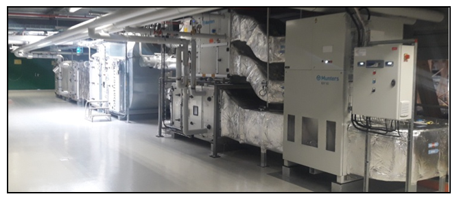 | Figure 1. Overview of a typical HVAC of the case study |
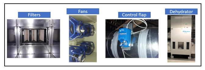 | Figure 2. Pictures of different HVAC elements |
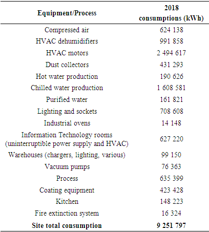
3. Site Electrical Consumptions
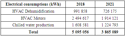
- Several equipment on site use electricity. The electricity is supplied by four transformers (three 1250 kVA oil transformers and one 630 kVA dry transformers). Total site electrical consumption for 2018 is 9 251 797 kWh before application of the HVAC carbon emissions reduction methodology. Actions have been started beginning of 2019.Table 1 contains electrical consumptions of all equipment/process during 2018 (the reference year).
|
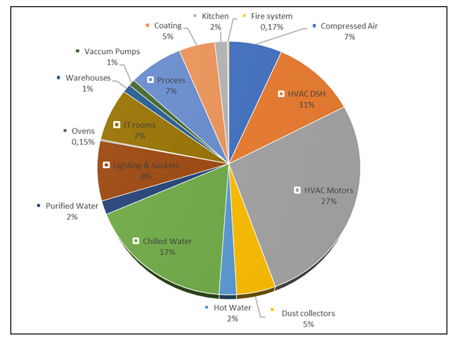 | Figure 3. 2018 site’s electrical consumption repartition in % |
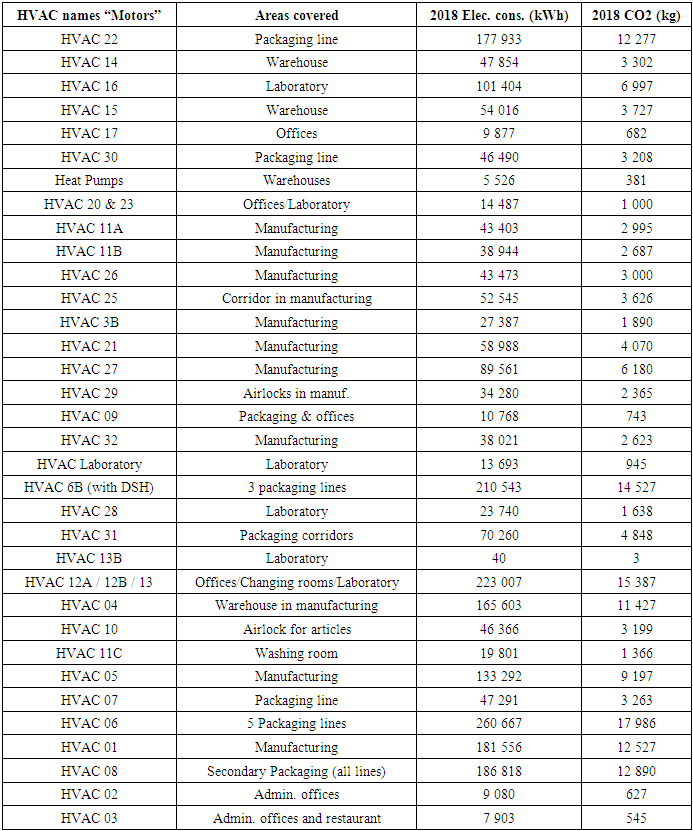
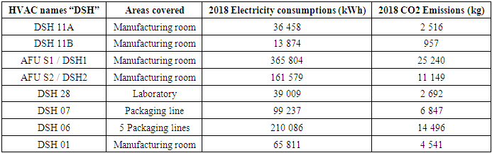
4. HVAC Electrical Consumptions & CO2 Emissions
- HVAC motors are the highest electrical consumers (27% of site’s electrical consumption). Therefore, it is important to know consumption of each system. Table 2 summarises those consumptions.
|
|
5. Methodology
- The methodology used in this case study to reduce the consumption of each HVAC is the following:• 1st step = Reduce quantity of airo Goal is to reduce as much as possible the quantity of air to be treated while respecting all the requirements of the area to be treated (e.g., avoid cross contamination between area).• 2nd step = Reduce air treatment periods o After deep analysis air treatment can be minimized in some situation.• 3rd step = Efficient air treatment by design o This step consists of maximizing the efficiency of the air treatment thanks to an adapted design. • 4th step = Efficient air treatment by managemento This last step is to define and put in place a high-level management during the whole life of the HVAC (e.g., continuous monitoring with a building monitoring system).Figure 4 represents the methodology defined and applied and the associated actions.
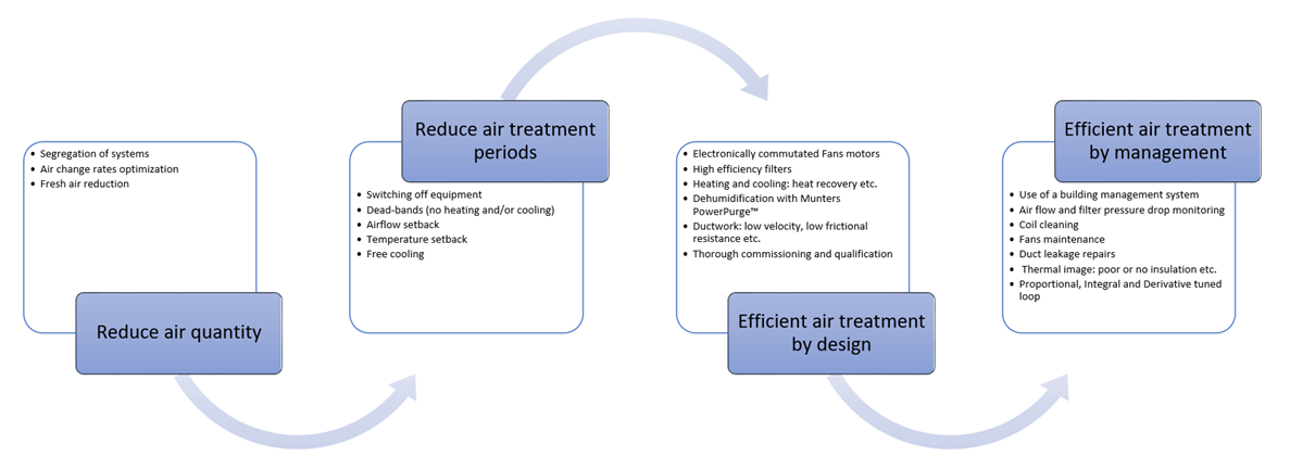 | Figure 4. Flowchart of HVAC research methodology |
6. First Step: Reduce Quantity of Air
6.1. Air Changes Rates
- An air equipment is often overdesigned to attain the requirement in the user requirement specification (e.g., because of quality requirement). Air change rates (ACR) can be reduced in most of the cases while maintaining the environmental conditions (e.g., for product protection). ACR are influenced by: • Initial design conditions• Heat gains in the room• Containment between rooms (pressurization) • Make up air for local extractA good air distribution will also allow colder/heater air to be delivered in smaller quantities for same cooling/heating effect.It is important to exclude fixed large equipment such as vessels from room volume to calculate air change per hour.“The Fan Affinity Law (physics) states that the power used by a fan motor is reduced exponentially as the speed is reduced” [6].In figure 5, we can observe that: • 20% reduction in fan speed = 47% reduction in power• 50% reduction in fan speed = 87% reduction in power
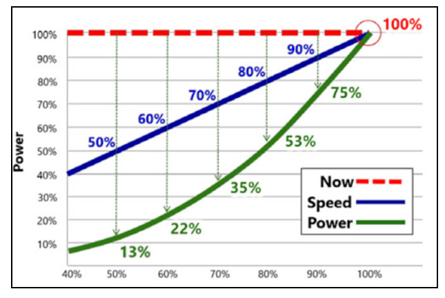 | Figure 5. Affinity fan laws: Power and Air Flow [6] |
 | (1) |
6.2. Fresh Air Reduction
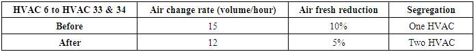
- Fresh air is required for occupant health and for pressurization. For each area, the air fresh air rate is analysed. The aim is to recycle as much as possible the extracted air because it has been already treated. The following element have been considering in reducing fresh air: • Possible pressure cascade losses• Room leakage • Duct leakage• Exhausted air through dust extractIn this case study, fresh air reduction has been applied to HVAC 6. See results in section 10.
6.3. Segregation of Systems
- Implementation of separate air supply systems for areas with different requirements to: • Minimize local re-heat for areas with different temperature requirements• Enable air supply systems to intermittently occupied areas to be switched off or reduced (subject to area classification)• Minimize pressure drops from excessively long or complex distribution ductsIn this case study, segregation of systems has been applied to HVAC 6. See results in section 10.
7. Second Step: Reduce Air Treatment Periods
7.1. Setpoints and Dead-bands (Temperature/Relative Humidity)
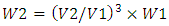
- The principle is to ensure appropriate dead-bands (or offsets) for heating and cooling [8,9]. For reaching that, single setpoint values must be avoided. This will help eliminate unnecessary simultaneous heating and cooling as shown in figure 6.
 | Figure 6. Typical energy efficiency temperature set point and control bands [10] |
7.2. Temperature Setback
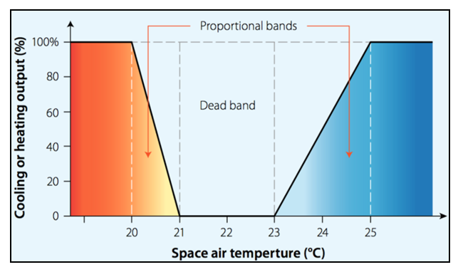
- When rooms are occupied, it is best to have a dead-band control in operation. However, when rooms are unoccupied or not in use a setback can be introduced. Temperature setback is place for nearly 8 years on several HVAC. This action is indicated in this case study for information.As seen in figure 7, this setback widens the dead-band and therefore reduce the demands on the HVAC systems.
 | Figure 7. Room temperature setback control |
7.3. Airflow Setback
- Switching off equipment when not in use is the best energy savings (demand based). Airflow setback is widely deployed in non-critical areas such as administrative areas and cafeterias. Airflow setback can be deployed in production areas when not in use (outside shifts). Nevertheless, it is important to maintain room pressurization where required. Airflow in laboratories is setback during out of working hours but maintain temperatures and relative humidity within limits and maintain a negative pressure where required.A building monitoring system is used for managing setback mode of all equipment. This tool can realize complex sequence of operations. Every week before the new week coming, a quick meeting is set between utilities service in charge of HVAC and production planning service for sharing opening of production areas (for then setting HVAC hours of setback in the building monitoring system).Airflow setback is place for nearly 8 years on several HVAC. This action is indicated in this case study for information.
7.4. Free Cooling
- When conditions are favourable (outside air temperature is below return air temperature), the outdoor air damper is the first stage of cooling [11].During the spring and fall seasons especially, the opportunity to use outdoor air to provide free cooling saves energy while also boosting indoor air quality. To accomplish this sequence air handling unit are equipped with modulating return and outdoor air dampers. Temperature (or enthalpy) sensors are also in place for allowing the building monitoring system to determine which type of air is most appropriate for cooling (outside air for free cooling or return air for mechanical cooling).Free cooling is place in place on many HVAC. This action is indicated in this case study for information.
8. Third Step: Efficient Air Treatment by Design
- Overdesign must be avoided in designing HVAC systems and an optimization of HVAC systems design is the solution to reach that objective [12].
8.1. Motors and Fans Specifications
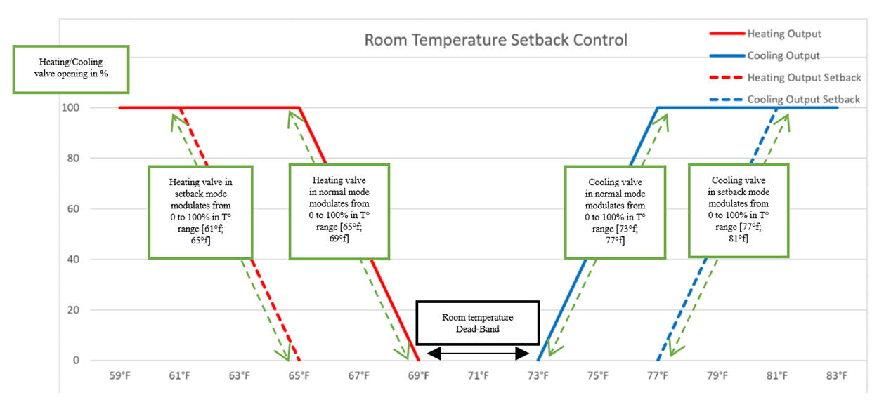
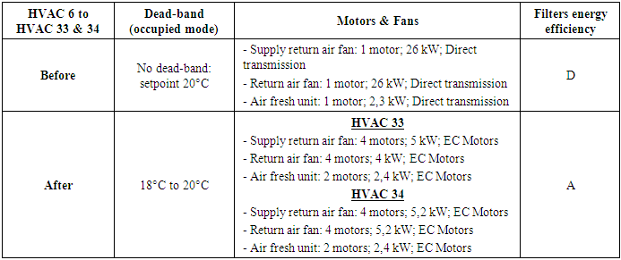
- Fans design should be of the highest efficiency available (technology is advancing quickly). Therefore, the fan is selected to provide maximum efficiency at the actual air flow required, or the most frequent air flow for fans that will operates across a range of airflows. Fans are fitted with backward curved blades. Fan walls consisting of multiple fans are considered in place of large single fans to improve efficiency part load efficiency. Fans are also direct driven with high efficiency motors.All motors are high efficiency Electronically Commutated (EC) motors [13]. An EC motor has the following key attributes:• Brushless Direct Current (DC) motor (rotor and stator)• A permanent magnetic rotor (see technical differences with electromagnet rotor in figure 8)• Alternative Current (AC) is converted to Direct Current (DC) by electronics commutation • An Electronic card modulates the speed of the DC motor
 | Figure 8. Differences between permanent magnet and electromagnet [14] |
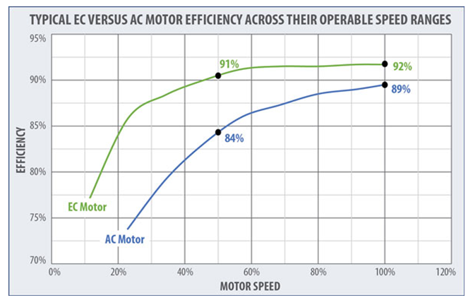 | Figure 9. Typical EC Versus AC Motor Efficiency across operable speed ranges [16] |
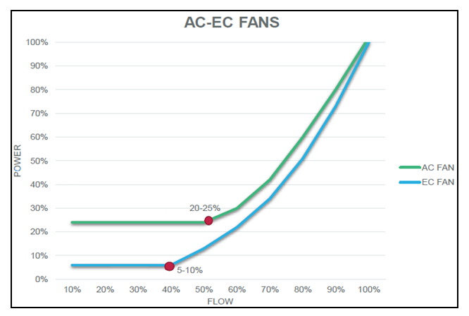 | Figure 10. AC Fans vs EC Fans |
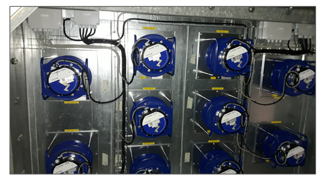 | Figure 11. Example of direct drive multi grid fans with EC motors installed |
8.2. Filters
- Filters are keys element in HVAC [16]. They are used in industrial, commercial, and residential HVAC applications. A filter spends on average 1700 kWh/year. For example, it is:• 3 times more than a dryer,• 5 times more than a class A refrigerator,• 13 times more than an iron, ...It should also be remembered that a high efficiency filter will certainly create good air quality, but also pressure drops synonymous with energy expenditure.It is necessary to conduct a global, energetic, and environmental reflection. It is possible to save energy but not at the expense of filtration efficiency. The ventilation and associated equipment of a building represent up to 70% of its overall energy consumption and are often overlooked.The filtration strategy in this case study is the following: • Maintain/improve current filtration air quality• Change to low energy filtration • Remove low-capacity panel filter• Consider removing panel filters and just having bag filters large capacity• Add pressure/volume controlEnergy classification and standard EN779: 2012Eurovent's energy efficiency classification represents a powerful tool [17], as it allows to know the class of annual energy consumption. Today, all Eurovent member air filter suppliers must affix an energy label (as illustrated in figure 12) on each filter box, rated from A (lowest energy consumption, between 0 and 1200 kWh/year) to G (the highest).
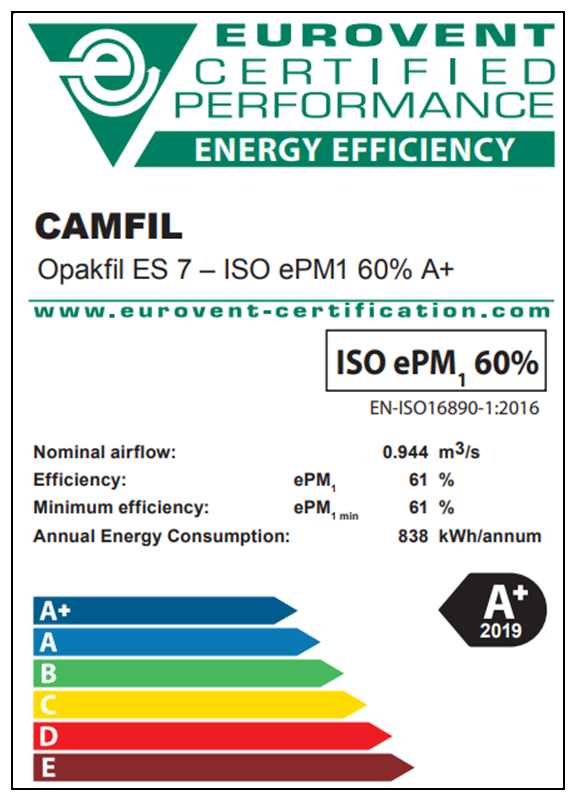 | Figure 12. Example of filters energy efficiency labelling |
8.3. Heating and Cooling
8.3.1. Heat Recovery
- Heat recovered from exhaust air is used to pre-heat fresh air when there is enough temperature or enthalpy difference between supply air and exhaust air streams [18]. This requires supply air and extract air fans to be in the same location.Thermal wheels are the first option. “The overall efficiency of rotary wheel heat recovery is generally much higher than that of any other air-side heat recovery system due to the nature of the heat wheels, which allow heat to transfer from the exhaust stream to the supply stream without having to pass directly through the exchange medium” [19].Plate heat exchangers or heat pipe recovery systems are used where thermal wheels cannot be used.Bypass arrangements are used in installations where required by seasonal climatic conditions.By setting higher discharge air temperatures when demand for cooling decreases, unnecessary reheating of make-up air supply is reduced.
8.3.2. Heating and Cooling Coils
- Heating coils are supplied by hot water from high efficiency hot water boilers and a heat pump. Pre-heat/re-heat coils, batteries and room radiators are also supplied with hot water. Steam or electricity are not normally be used. A conscious design change to use low temperature/hot water heating will facilitate the use of combined heat and power [20] or renewable energy sources in the future.Cooling coils are supplied by chilled water.Variable refrigerant volume systems are always evaluated for buildings with simultaneous heating and cooling loads [21].Coils are designed to minimize air flow pressure drop. Coil tube velocities are limited to improve holding time and increase heat transfer.Hot water and chilled water coils are modulated by two port valves fed by variable flow constant pressure circulation systems to minimize pumping loads.Floating temperature control of central Air Handling Unit heating/cooling plant is link to control of terminal plant to minimize heat/cool conflict.Cooling to dew point only takes place at times when dehumidification is necessary.Temperature probes are installed, and the building monitoring system is designed to detect failed control valves on heating and cooling coils (a frequent cause of significant wastage of energy).
8.3.3. Heating and Cooling Ductwork
- High standards of ductwork insulation are applied.
8.3.4. Decentralized Heating Systems
- Decentralized space heating systems provide an energy efficient solution where demand is intermittent, or service distribution runs are long. This could include localized gas fired air heaters or Low Temperature Hot Water (LTHW) radiators fed from high efficiency gas or oil-fired boilers [22].
8.4. Dehumidification
- The most energy efficient method of dehumidification is evaluated for each application:• Dew point refrigeration• Solid desiccant• Liquid desiccantThe evaluation takes account of humidity and temperature set-point and dead-band requirements against local climatic conditions.For desiccant systems precooling is considered. Regeneration heat is from the most energy source (hot water in this case study). Where hydroscopic products are exposed, low relative humidity air is required. Therefore, we try as much as possible to minimize the room volumes. We also segregate areas to avoid feeding low relative humidity into entire manufacturing spaces.We ensure dehumidification units are used with energy minimization features (i.e., regeneration air to air and heat recovery).Desiccant dehumidifiers are more economical than refrigeration-based dehumidifiers below 45% RH.Liquid desiccant dehumidifier [23]: As seen in Figure 13, a liquid desiccant comprises one absorber mechanism with strong liquid desiccant and one regeneration mechanism with dilute liquid desiccant.
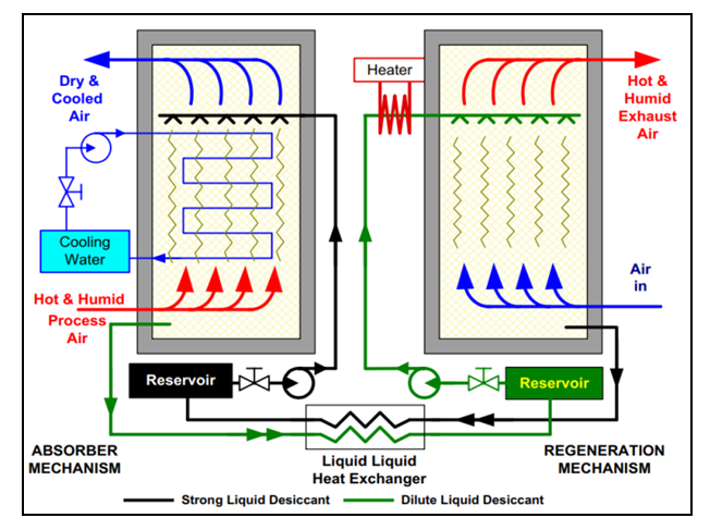 | Figure 13. Liquid desiccant functioning principle [24] |
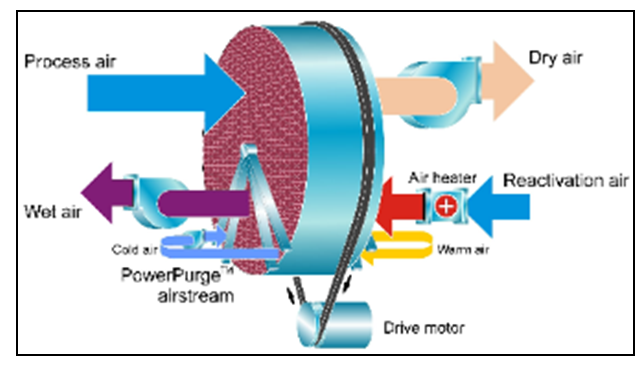 | Figure 14. Munsters rotor principle with PowerPurge™ [25] |
8.5. Ductwork
- Ductworks and fittings are designed and sized for low air velocity (e.g., 10% oversized will deliver 20% less fan pressure for the life of the system). Ductwork and fittings are also designed and installed to provide lowest practicable frictional resistance/losses, with minimum balancing requirements [26]. High efficiency diffusers are used to minimize pressure drop. Ductworks are also designed, installed, and tested to minimize leakage.Supply air and extract fans ductworks are located close together to facilitate heat recovery.
8.6. Installation & Commissioning
- One of the most common issues of high energy use in HVAC is caused by poor or nonexistent commissioning [27]. Fans, filters, ductworks, and fittings including bends, louvers etc. are installed with care to minimize frictional losses and pressure drops. Care is taken during commissioning to ensure that air flows, pressure drops, and fan power is minimized in accordance with the scheme design. A careful and thorough commissioning is done for each HVAC (e.g., commissioning checklist and validation documentation are carefully prepared).
9. Fourth Step: Efficient Air Treatment by Management
- Systems will over time drift from operation set points. A continuous maintenance regime is very important to sustain energy efficiency [28,29]. Consequently, a program of system survey review, maintenance and recommissioning is established for all HVAC.
9.1. Filtration
- Filter pressure drop is monitored by electronic pressure differential indicators. Filters are replaced (with high efficiency filters) regularly to minimize pressure drop.
9.2. System Balancing
- Air flows and pressure drops are measured at appropriate intervals to ensure compliance with the detailed specification (and good manufacturing practices requirements where appropriate).
9.3. Coil Cleaning
- The air side of coils are regularly deeply cleaned and protected using specialist treatment such as Coil-Flo™. This operation permits to reduce air side pressure drop increasing fan loads, and to promote more efficient heat transfer [30]. In HVAC with high fresh air rate, the cleaning frequency is higher.
9.4. Fans
- Allowances are made in the design to ensure eroded/fouled fan blades can be readily removed, obstructions to air intakes cleared and dampers freed etc. during maintenance. Thanks to EC.
9.5. Duct Leakage and Repair
- Supply and extract duct leakage are all identified. Routine inspections are in place and repairs are done as soon as possible. Duct insulations are also repaired as soon as possible.
9.6. Thermal Image
- Thermal Image camera survey of AHU’s, ducts, cold/hot water pipes and fabric is done regularly. All poor or no insulation and all leaking (valves etc.) are fixed quickly.
9.7. Building Management System
- “Building Management System (BMS) is a high-technology system installed in buildings that controls and monitors the building’s mechanical and electrical equipment such as air handling, fan-coil unit, cooling plant systems, lighting, power systems, fire systems, and security systems”. “The objective of a BMS is to achieve more efficient building operation at reduced labor and energy costs and to provide a safer and more comfortable working environment for building occupants” [31].The BMS used in this case study control and monitor: Central HVAC units; Packaged plant; Terminal unit (Variable air volume and fan coil units); Central and dispersed boiler plant; Chillers; Unitary air conditioning systems (roof top units).Regular diagnostics and optimization of the control strategies are in place. The diagnostics will identify energy savings improvements related to: • Set time schedules for occupancy• Room conditions (temperature/relative humidity) at lower end of allowable range• Non-production hours set back overlapping of heating and cooling stages (i.e., eliminate heating/cooling systems “fighting”)• Heating/cooling valves bypassed (in manual)• Heating/cooling control valves at 100%• Set point control tolerances; dead bands; Control is set to manual; Set point is not being achieved• Pressure regimes and filtration pressure drops• Heating and cooling control valve actuators are checked to ensure seats are not passing• Fan speed is set to 100% (not dynamically controlled)
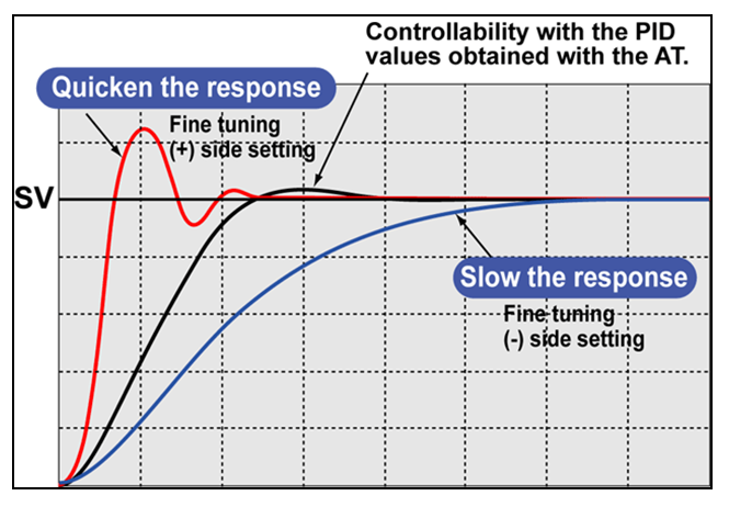
9.8. Proportional, Integral & Derivative Control Loops
- A poor control loops will increase energy consumption.The goal of tuning a PID loop is to make the control stable, responsive and to minimize overshooting [32,33]. These goals, especially the last two, conflict with each other. It is necessary to find a compromise between responsiveness and minimal overshoot as shown in figure 15.
 | Figure 15. PID controls Loop |
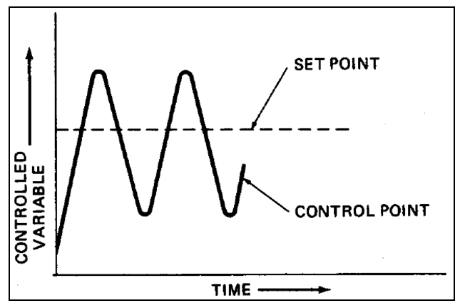 | Figure 16. Poor variable control |
9.9. Verify Performance is Maintained
- System performance will degrade over time and therefore energy consumption will increase as represented in figure 17:• If no monitoring/intervention is made, then most improvements will be undone within 12-24 months.• People love to fiddle with controls – often get over a temporary problem, but then forget to fix the root cause. e.g., put control in manual.A disciplined approach has been introduced to track changes:• Energy impact analysis for all changes by site energy expert.• Routine monitoring (part of routine maintenance practice and metering is a helping).
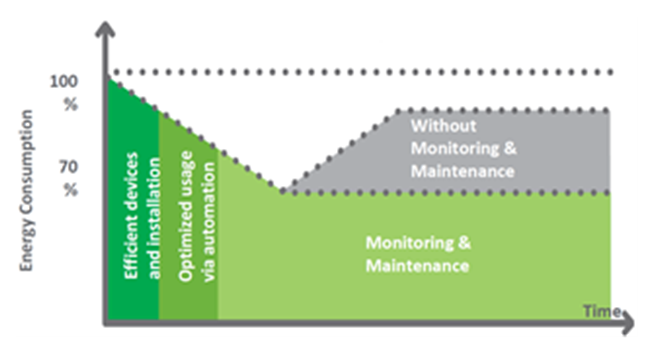 | Figure 17. Energy management impact on consumption over time |
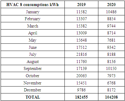
10. Results
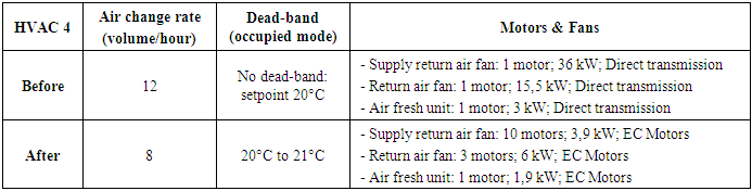
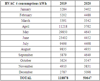
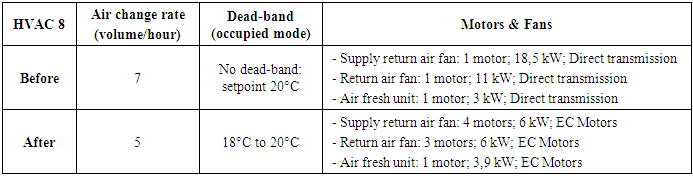
- HVAC 4 is one of the major HVAC and it covers the warehouse in manufacturing area. Table 4 contains the different actions done in 2019 (quarter 4) for reducing its carbon emissions.
|
|
|
|
|
|
|
11. Conclusions
- In industrial environment, HVACs are generally among the high consuming equipment. Without a proper strategy their consumptions can continuously increase and therefore their carbon emissions. The methodology defined and deployed in this case study is a tiered methodology starting by the design and ending by the management. The methodology can be applied to similar industrial sites and even to administrative or commercial buildings fitted with air treatments systems.The application of this methodology has permitted to reduce HVACs carbon emissions by 24% in 3 years while HVAC represents more than 55% of site’s carbon emissions.
Abbreviations
- AC = Alternative CurrentAFU = Air Fresh UnitAHU = Air Handling UnitBMS = Building Management SystemCO2 = Carbon dioxide CHP = Combined Heat and PowerDC = Direct CurrentDSH = DehumidifierEC = Electronically CommutatedHVAC = Heating, Ventilation and Air ConditioningLTHW = Low Temperature Hot Water PID = Proportional, Integral & DerivativeRH = Relative Humidity
ACKNOWLEDGEMENTS
- I wish to thank my family and colleagues for their permanent support and encouragement.