-
Paper Information
- Paper Submission
-
Journal Information
- About This Journal
- Editorial Board
- Current Issue
- Archive
- Author Guidelines
- Contact Us
International Journal of Energy Engineering
p-ISSN: 2163-1891 e-ISSN: 2163-1905
2020; 10(2): 59-66
doi:10.5923/j.ijee.20201002.04

Modelling and Numerical Simulation of Greenhouse Effect in a Solar Collector with a W-Shape Cover
 Abstract
 Reference
 Full-Text PDF
 Full-text HTML
Tene Patrick 1, Edoun Marcel 1, 2, Kuitche Alexis 1
1Laboratory of Energetic and Applied Thermal Process, ENSAI, University of Ngaoundere, Cameroon
2The U.I.T, University of Ngaoundere, Cameroon
Correspondence to: Edoun Marcel , Laboratory of Energetic and Applied Thermal Process, ENSAI, University of Ngaoundere, Cameroon.
| Email: |  |
Copyright © 2020 The Author(s). Published by Scientific & Academic Publishing.
This work is licensed under the Creative Commons Attribution International License (CC BY).
http://creativecommons.org/licenses/by/4.0/

The work presented concerns the modelling of the greenhouse effect in solar thermal collectors with W-shape cover. A mathematical model was used to evaluate the net infrared radiation absorbed, the radiation lost by the absorber and the radiation pathways in the collector. A comparison was made between the three collector configurations: the double-glassed flat collector, semi W-shape collector and W-shape collector. The cover of the W-shape collector has double glass whereby the upper glass is flat, and the lower glass is w-shape. The absorber is also W-shape. The results show that at the maximum of solar radiation, the adsorbed infrared radiation is 678 W.m-2, 620 W.m-2 and 433.2 W.m-2 respectively for the double-glassed flat collector, semi W-shape collector and W-shape collector. The radiation losses are smaller in the W-shape collector (234.3 W.m-2) wherever when the absorber is flat, the radiation lost is greater: 250 W.m-2 and 265 W.m-2 respectively for the double-glazed flat collector, semi W-shape collector. Analysis of the angle factors of the transparent cover and the absorber showed a significant influence on the greenhouse effect in the W-shape collector, when the angle of the W-shape cover increases, the absorbed IR radiation also increases as the radiation losses decrease. This result is validated when the W angle of the absorber is constant. We also saw that, the absorbed IR radiation and the radiation lost at the absorber level grow with the W angle of the absorber.
Keywords: Solar energy, W-shape collector, Infrared radiation, Greenhouse effect
Cite this paper: Tene Patrick , Edoun Marcel , Kuitche Alexis , Modelling and Numerical Simulation of Greenhouse Effect in a Solar Collector with a W-Shape Cover, International Journal of Energy Engineering, Vol. 10 No. 2, 2020, pp. 59-66. doi: 10.5923/j.ijee.20201002.04.
Article Outline
1. Introduction
- The revealed limits of fossil fuels, the threat posed by global warming and the ever-increasing need for global energy have prompted exploration of other so-called renewable energy sources, including solar energy. Considered to be the world’s oldest energy, on which almost all other energy sources depend, it is used either directly or after transformation into other forms of energy (thermal energy, electric energy).The central element of the solar thermal energy applications is the solar thermal collector. It transforms the radiant energy of the sun into thermal energy extracted by the flowing fluid. This energy is used in various applications such as drying, domestic and industrial heating, solar cooling production, etc. [1]. Most of the research is being devoted to the development of solar collectors using water as heat transfer fluid in terms of thermal efficiency. In general, there are few studies on solar collectors using air as heat transfer fluid because, air does not have a better heat exchange efficiency due to its low thermo-physical properties [2]. However, with the current technological development, this field has undergone significant renewal in theory and experiment [2-6]. Thus, several scientific studies have been carried out on these collectors, with the aim of optimizing the useful energy transmitted to air, by acting on the optical (relating to transparent covers) and geometric (shapes and dimensions) properties of the collector, as well as all other parameters that may affect its thermal performance [7-10]. Transparent cover in a collector has the dual function of allowing the maximum amount of solar radiation to pass and avoiding the cooling of the absorber, reducing air convection phenomena and "blocking" emitted infrared radiation [11,12]. Such a device thus represents a real trap to solar radiation, which can be improved by equipping the collector with an additional cover (double cover) or by playing on the properties of the material of the cover [13-14]. It then realizes greenhouse effect, which involves both solar radiation and infrared radiation.Important studies have been carried out in the context of the optimization of flat-sided solar air collectors [15]. In particular, there is an important bibliography on exchange modelling in collectors [16-19] but so far, it has only been concerned with macroscopic phenomena and has only been concerned with sensors whose transparent cover whether simple, double or triple glazing is always flat. Also, in all this work the influence of infrared radiation (greenhouse effect) has always been mentioned superficially. Although mathematical modelling of infrared thermal radiation inside the greenhouse has been developed [20,21], such work with regard to solar air collectors are quite rare.A new solar collector with W-shaped cover form was design and their thermal performance was experimentally characterized [22]. In this article, we have focused our attention on modelling and numerical simulation of the greenhouse effect of that new solar collector.
2. Material and Methods
2.1. Material and Physical Model
- The Fig. 1 shows the W-shape geometry [22].
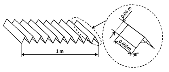 | Figure 1. Representation of the W-shape glass and the absorber form |
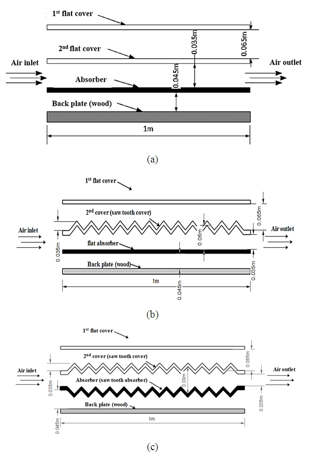 | Figure 2. Physical models: (a) flat plate solar collector, (b) semi W-shape solar collector, (c) W-shape solar collector |
2.2. Concept of Multiple Reflections
2.2.1. Double-glazed Flat Solar Collector
- The useful profile of a double-glazed flat collector can be assimilated to three parallel flat surfaces. What we are interested in are the radiation exchanges between the first glass
 the second glass
  and the absorber
  as shown in Fig. 3. The rays can take a multitude of paths.
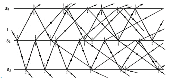 | Figure 3. Possible paths of radiation in the double-glazed flat solar collector |
 is a diffuse emission grey surface, the amount of radiation actually absorbed may be determined [23,24]:
 | (1) |
 | (2) |
 | (3) |
 | (4) |
 | (5) |
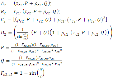
2.2.2. Semi W-shape Collector
- The semi W-shape collector can be assimilated to three surfaces exchanging radiation as shown in Fig. 4. What we are interested in are the radiation exchanges between the flat glass (S1), the W-shape glass (S2) and the absorber (S3).
 | Figure 4. Possible paths of radiation in the semi W-shape solar collector |
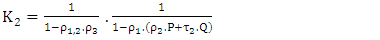
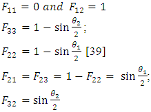
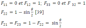 Where θ is the angle of the W-shape sections.In the particular case where (S3) is a diffuse emission grey surface, the amount of radiation actually absorbed is given by equation (1).For this configuration,
  is given by:
 | (6) |
 | (7) |
 | (8) |
 | (9) |
 | (10) |
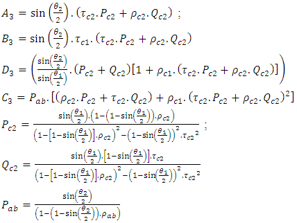
2.2.3. W-shape Collector
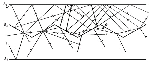
- The W-shape collector can be assimilated to three surfaces exchanging radiation as shown in Fig. 5. What we are interested in are the radiation exchanges between the flat glass (S1), the W-shape glass (S2) and the W-shape absorber (S3).
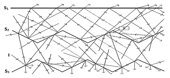 | Figure 5. Possible paths of radiation in the W-shape solar collector |
 Where
Where  and
and  are the angles formed by the W-shape sections of the second pane and the absorber respectively. In the particular case where
  is a diffuse emission grey surface, the amount of radiation actually absorbed is given by equation (1).
  and
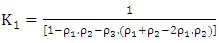
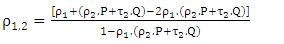
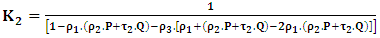
and  are given by the equations (7) and (8).The factor materializing the phenomenon of multiple reflections is given by:
 | (11) |

2.3. Net Infrared Radiation
2.3.1. Different fluxes
- Tn is the absolute temperature of the surface n. Its emissive power, that is the rate of energy emitted per unit of surface, is given by the Stefan-Boltzmann law:
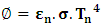 | (12) |
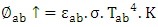
 reaching the absorber is given by:
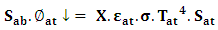 | (13) |
 which represents the infrared emittance of the sky, known to be somewhere between 0.72 (clear sky) and 1 (overcast sky) [25].X takes into account collector configuration (angle factor, roofing transmission coefficients) and multiple reflections.
2.3.2. Flux Emitted by the Transparent Cover
- Flux density descending from the thermal radiation emitted by the transparent cover
 which reaches the absorber is given by:
 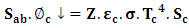 | (14) |
2.3.3. Flux Emitted by the Absorber
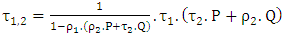
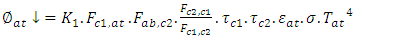
- The radiation emitted by the absorber also gives rise to a descending flux density
 It includes two contributions: the flux density of radiation emitted by the absorber which after reflection at first contact with the cover, is finally returned, and the corresponding flux density which is transmitted during its first contact with the cover but which is finally returned after a certain number of exchanges in different parts of the cover, while taking into account the multiple reflections.
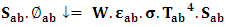 | (15) |
2.3.4. Absorbed Infrared Radiation
- The radiation absorbed by the sensor is then simply deduced:
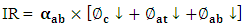 | (16) |
2.4. IR radiation Losses
2.4.1. Different Fluxes
- Ascending thermal radiation fluxes have the following flux densities:
 | (17) |
 | (18) |
 | (19) |
2.4.2. Radiation Losses
- The radiation losses by the absorber are deduced using equation (20):
 | (20) |
3. Results and Discussion
3.1. Profil of Infrared Radiation
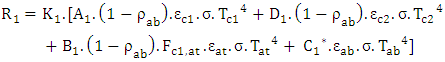
- Infrared radiation absorbed by the double-glazed flat collector takes into consideration the following different fluxesFirst cover:
 | (21) |
 | (22) |
 | (23) |
 | (24) |
 the amount of infrared radiation absorbed is given by the equation (25):
 | (25) |
 Following the same reasoning, the amount of infrared radiation absorbed by the semi saw-teeth collector is given by the equation (26):
 | (26) |
 The amount of infrared radiation absorbed by the saw-teeth collector is given by the equation (27):
 | (27) |
 The Fig. 6 shows the net absorbed IR radiation curves for the three double glazed sensor configurations. The graph also showed the evolution of solar radiation.
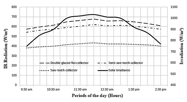 | Figure 6. Infrared Radiation absorbed by the collector |
 but nevertheless reduces the amount of radiation from the atmosphere
  the first cover
  and the amount emitted by the absorber that is returned to it
  The saw-teeth collector has the lowest amount of absorbed IR radiation, approximately 433.2 W.m-2 at 12:00 am. This is due, in addition to the reasons listed above (temperature of the sensor elements and geometry of the second cover), to the geometry of the absorber. The saw tooth geometry of the absorber in this collector configuration significantly reduces the absorbed IR radiation.
3.2. Radiation Losses at the Absorber Level
- The radiation losses at the level of absorber on double-glazed flat collector are given by the equation (28):
 | (28) |
 The absorber radiation losses in case of the semi W-shape collector are given by expression (29):
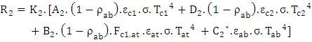 | (29) |
 The radiation losses at the level of absorber of W-shape collector are given by expression (30):
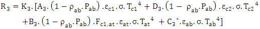 | (30) |
 In Fig. 7, we show the profiles of radiation losses for different configurations: double-glazed flat collector, semi W-shape collector and W-shape collector.
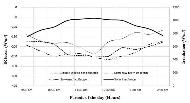 | Figure 7. IR radiation losses at the absorber for different configurations |
3.3. Influences of Angle Factor
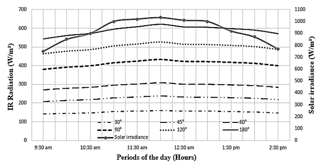
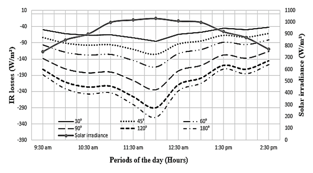
3.3.1. Case of the Semi W-shape Collector
- Fig. 8 and 9 are obtained by varying the angle of the W-shape of collector. In Fig. 8, we show the absorbed IR radiation curves for different angle values, while in Fig. 9 the radiation losses (at the absorber level) for the same angle values.Analysis of the curves shows that the angle value of the glazing tooth has an important effect on the absorbed IR radiation and on the losses of IR radiation in the semi saw-teeth collector. The Fig. 8 shows that absorbed IR radiation increases with the angle of the saw tooth. It is particularly important when the angle of the saw tooth is obtuse. For IR radiation losses (Fig. 9), they decrease when the tooth angle value increases. These results are consistent with those in the literature.
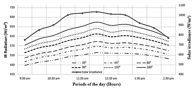 | Figure 8. IR radiation absorbed by the semi W-shape collector for different angle values of the W glass |
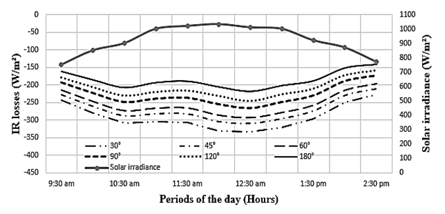 | Figure 9. Radiation losses at the absorber of the semi W-shape collector for different angle values of the W glass |
3.3.2. Case of the W-shape Collector
3.3.2.1. Angle of W-shape Glass
- Fig. 10 and 11 respectively represent the net absorbed IR radiation curves and the radiation loss curves in the W-shape collector for different angle values of the W of the transparent cover when the angle of the W absorber is fixed.Analysis of the curves shows that, when the value of the angle of the absorber tooth is fixed, the variation in the glazing angle has a significant effect on the absorbed IR radiation and on the losses of IR radiation in the saw-teeth solar collector. The absorbed radiation increases with the angle of the glazing (Fig.10). With regard to radiation losses (Fig. 11), they decrease when the tooth angle value increases. However, the variations are not as large as for absorbed radiation.
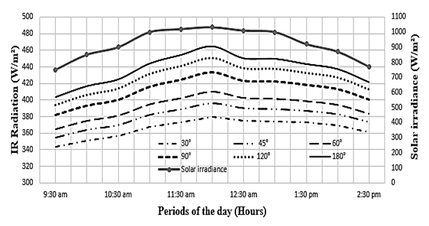 | Figure 10. IR radiation absorbed by W-shape collector for different angle values of the W-glass |
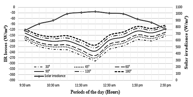 | Figure 11. Radiation losses of the W-shape collector for different angle values of the W glass |
3.3.2.2. Angle of the W-shape Absorber
- In Fig. 12 and 13 respectively, we represent the net absorbed IR radiation curves and the radiation loss curves in the W-shape collector for different angle values of W of the absorber when the angle of W of the transparent cover is fixed.
 | Figure 12. IR radiation absorbed by the W-shape collector for different angle values of the W absorber |
 | Figure 13. Radiation losses of the collector for different angle values of the W absorber |
4. Conclusions
- In this article a mathematical model has been developed to calculate the net infrared radiation absorbed as well as the radiation losses at the absorber level for the semi W-shape and W-shape solar collectors. The results showed that the maximum values of the net absorbed radiation are reached at solar noon, when the solar radiation is maximum in the locality. The maximum loss value is also observed at solar noon for the W-shape solar collector but 30 minutes later for the other two solar collectors. This is due to the inertia of the flat absorbers (double-glazed flat solar collector and W-shape solar collector). From the comparative study, it is apparent that the W-shape solar collector absorbs the least amount of IR radiation (433.2 W.m-2) compared to the other two (678 W.m-2 and 620 W.m-2 respectively for the double-glazed flat and the semi W-shape solar collector). However, the analysis of the radiation losses at the absorber showed that it retains much more heat (234.3 W.m-2 compared to 250 W.m-2 and 265 W.m-2 respectively for the double-glazed flat solar collector and the semi W-shape solar collector), and therefore transmits as much to the coolant. The variation in the angle factors of the transparent cover and absorber showed that, when the angle of the W of the cover increases, the absorbed IR radiation also increases, while the losses of radiation to the absorber decrease; when the angle of the W of the absorber increases (W-shape solar collector), the amount of IR radiation absorbed and the losses of IR radiation to the absorber also increase.
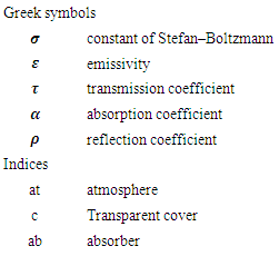
5. Nomenclature