-
Paper Information
- Paper Submission
-
Journal Information
- About This Journal
- Editorial Board
- Current Issue
- Archive
- Author Guidelines
- Contact Us
International Journal of Energy Engineering
p-ISSN: 2163-1891 e-ISSN: 2163-1905
2020; 10(1): 1-9
doi:10.5923/j.ijee.20201001.01

Latent Heat Storage During Melting and Solidification of a Phase Change Material (PCM) Embedded with a Porous Matrix of High Thermal Conductivity
 Abstract
 Reference
 Full-Text PDF
 Full-text HTML
Mehdi Fteiti 1, Amel Alaidrous 2
1Collegue of Preparatory Year, Umm Al Qura University, Makkah Al Mukarramah, Saudi Arabia
2Department Mathematical Sciences, Umm Al Qura University, Makkah Al Mukarramah, Saudi Arabia
Correspondence to: Mehdi Fteiti , Collegue of Preparatory Year, Umm Al Qura University, Makkah Al Mukarramah, Saudi Arabia.
| Email: |  |
Copyright © 2020 The Author(s). Published by Scientific & Academic Publishing.
This work is licensed under the Creative Commons Attribution International License (CC BY).
http://creativecommons.org/licenses/by/4.0/

The objective of the present work is to analyse numerically the effect of embedding a porous matrix (PMX) of high thermal conductivity within a phase change material (PCM) on the heat energy storage and recovery during the melting and solidification of a PCM. Most of the previous work put the insight mainly on the charging process during melting. The present study focuses on both charging and discharging during melting and solidification. Constant heat flux is applied through the left wall of a rectangular storage unit. The other walls are kept thermally insulated. At the end of the heating period, a cooling stage starts to extract the heat through the same wall. The ratio of thermal conductivities  of the porous matrix and the PCM will be taken as a parameter to study the efficiency of the thermal storage. Results are presented in terms of temperature fields, liquid-solid interface progress and plots of latent, and sensible heat storage. The study shows that a significant improvement in the heat storage/recovery can be achieved. For better efficiency, a compromise should be established between the ratio of thermal conductivity and the heating period.
Keywords: Latent heat storage, Thermal conductivity enhancement, Phase change material, Porous media, Natural convection
Cite this paper: Mehdi Fteiti , Amel Alaidrous , Latent Heat Storage During Melting and Solidification of a Phase Change Material (PCM) Embedded with a Porous Matrix of High Thermal Conductivity, International Journal of Energy Engineering, Vol. 10 No. 1, 2020, pp. 1-9. doi: 10.5923/j.ijee.20201001.01.
Article Outline
1. Introduction
- Thermal energy storage TES is a promising alternative for bridging the gap between energy demand and supply during peak periods. Solar radiation, which is an exhaustible clean and renewable source of heat, and heat wasting in industrial processes, can be used as buffering systems. Thermal energy is easily storable by raising the temperature of a storage medium (sensible heat storage SHS) or changing its state (latent heat storage LHS). But, Latent heat storage during melting and solidification is much more attractive because of its high storage capacity. Another advantage, LHS occurs in a small range of temperatures and requires much lower volume. Phase change materials have shown great potential in thermal storage applications. Providing new PCMs with a variety of characteristics is now an attractive field of research. Agyenim & al. [1] presented an overview of different PCMs and their applications in thermal storage systems, operating at low temperatures (below 60°C) suitable for domestic heat storage applications. Different configurations of storage units studied numerically and experimentally are quoted in this paper. A survey on storage materials operating at high temperature (between 120°C and 1000°C) used for industrial applications, was reported by Murat [2]. Recently, Yaxue & al. [3] reviewed the state of the art of PCMs and their applications, where a deep insight was attached to the development of new materials of better storage performance. The major drawback of such PCMs is related to their low thermal conductivity which limits the charge and discharge rates during melting and solidification. Thermal conductivity enhancement (TCE) is crucial to improve the efficiency of LHS systems. During the last decades, different methods of TCE have been proposed to overcome the large thermal resistance of the PCMs, a recent review was given by Liwu & al. [4]. TCE techniques are mainly based on two strategies: The first, consists of the incorporation within the PCM of dispersed high thermal conductivity particles with variable volume proportions [5]. The size of these particles varies from Nano-scales [6] to micro scales [7]. The second strategy is based on the inclusion of different types of fixed structures such as fins, heat pipes, metal foam, strips, and ships. The inclusion of fins is a systematic option inspired from the heat exchangers design and consists of the extension of the surface area between the PCM and the heated fluid [8-9] Sciacolvelli & al. [10] apply Y-shaped fins with different lengths and angle spacing in a shell-and-tube LHS unit and showed that TES may be improved by 24%. Al-Abidi & al. [11] investigated the efficiency of LHS inside a triplex tube experimentally and showed that the charging time is significantly reduced with the application of internal and external fins. The use of heat pipes can be found in [12-13]. Sharifi & al. [14] investigated experimentally and computationally the melting and solidification of PCM surrounding a vertical heat pipe, finned with metal foils in a vertical cylinder. The combination of HP-metal foils shows a better increase of the phase change rates than the use of only one of them. Encapsulation and micro encapsulations of PCMs have been used as TCE techniques both in energy storage and energy building applications [15-16]. The inclusion of a porous matrix as a fixed structure, which is the subject of the present work, was among the earliest TCE techniques. It is easier to consider irregular fixed inclusions like porous structures. Tong & al. [17] studied the enhancement of thermal conductivity numerically by inserting an aluminium matrix in a cylindrical annulus saturated with a water/ice mixture. The study includes the effects of diffusion and natural convection during both melting and solidification, and the Darcy equation was applied for modelling the fluid flow. Results show a marked heat transfer enhancement for small volume fractions, but for further increase of the volume fraction, the enhancement rate does not increase linearly. Xavier & al. [18] considered a porous graphite matrix, a concentrated expanded natural graphite (CENG) to study the solidification of a paraffin/CENG composite. The thermal conductivity was improved from (0.24 K m-1 W-1) for pure paraffin to a range between (4 to 70 K m-1 W-1) depending on the graphite bulk density. The overall solidification time was reduced; nevertheless, an optimization was proposed due to the antagonist behaviours of the thermal power and thermal capacity according to the paraffin/CENG composition. Mesalhy & al. [19] studied, numerically, the melting between two concentric cylinders of a PCM inside a porous matrix of high thermal conductivity. The inner cylinder is heated by a temperature higher than the melting temperature of the PCM while the outer cylinder was kept adiabatic. The problem was solved numerically using the two equations model and the Darcy-Brinkman-Forchiemer formulation. Zhenyu & al. [20] investigated a shell-and-tube LHS unit holding a PCM embedded with a metal foam matrix. The numerical modelling took into account the natural convection and was solved using the enthalpy porosity formulation. They pointed out that heat transfer can be enhanced by more than seven times. Taeil & al. [21] analysed a latent heat thermal energy storage system (LHTES) for concentrated solar power consisting of a tank filled with tubes carrying heat transfer fluid, by using a PCM/Graphite foam composite, the number of tubes is dramatically reduced compared with the case of PCM without Graphite foam. Also, Zhuo & al. [22] investigated the melting of Sodium Nitrate (NaNO3) inside a metal skeleton of Copper where they numerically analysed the effects of heat conduction through the metal structure and natural convection in the liquid PCM. They also studied detailed parameters such as porosity and pore density of the metal matrix on the TES systems, in both melting and solidification processes. In recent work, Sayed & al. [23] studied the performance of a LHTES system made of a porous structure filled with a nano PCM which is a PCM combined with a volume fraction of a high thermal conductivity nanoparticles. The authors investigated the effect of varying the nanoparticles volume fraction and the natural convection on the melting process, but they did not consider the case of solidification. Their results focus on a comparison between a scale analysis and the numerical model proposed. To analyze the effect of pore distribution, Zilong & al. [24] studied the melting of PCM in a porous metal foam characterized by fractal geometry. They found that the dimension of the fractals and their distribution can affect the melting time. Recently, Esapour & al. [25] conducted a numerical investigation of the melting and solidification of a PCM embedded in a porous metal foam in a multi-tube heat exchanger. A recent numerical investigation has been conducted by Jourabian & al. [26] concerning the melting of a PCM in a porous media around two hot cylinders using the lattice Boltzmann method. Most of the previous works show that the enhancement of the thermal conductivity of the porous medium contributes to the increase of the storage performance of LHTES systems. The present study focuses on both the melting and solidification of the PCM and the effect of the thermal conductivity ratio on the performance of the energy storage/recovery processes. Furthermore, the study illustrates the relationship between the heating period and the thermal conductivity ratio and their effect on the sensible and the latent heat storage.
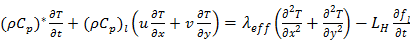
2. Problem Definition and Modelling
- Consider a two-dimensional rectangular domain of width L and height H (Fig.1), filled with a porous structure (solid matrix) and saturated with a PCM. Initially, the solid matrix and the PCM are supposed to be in thermal equilibrium at the melting temperature of the PCM. A constant and uniform heat flux Q will be applied on the left vertical wall of the cavity, while the remaining walls are kept insulated. The mathematical formulation of the problem is based on the volume averaging approach [27]. The Darcy-Brinkman model and the enthalpy-porosity formulation [28] have been adopted to describe the flow in porous media with one energy equation for the whole domain. The following approximations have been considered: - Thermo-physical properties are assumed to be constant in both liquid and solid phases, except for the density which is supposed to obey the Boussinesq assumption in order to take into account the natural convection.- The fluid in the liquid phase is assumed to be newtonian and the flow is unsteady and laminar.- Viscous dissipation is negligible.- Thermal equilibrium condition is adopted between the PCM and the porous structure.- No-slip boundary conditions for the velocities at the walls are implemented.
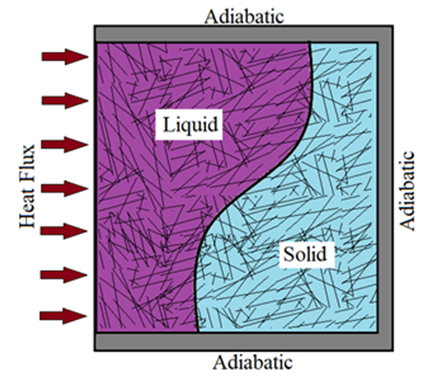 | Figure 1. Physical domain |
 | (1) |
 | (2) |
 | (3) |
 | (4) |
 is the porosity of the domain,
  the permeability of the porous medium,
  is the effective thermal conductivity of the PCM/PMX medium,
  is the thermal expansion of the liquid PCM, and
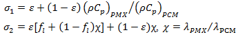
  is the local liquid fraction of the melted PCM.The effective heat capacity and the effective thermal conductivity are calculated in terms of the porosity as follows:
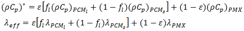 | (6) |
 and
and  Where
Where  and
and  is a reference heat flux.In dimensionless form the following equations are obtained:
 | (7) |
 | (8) |
 | (9) |
 | (10) |
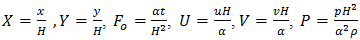
 is a parameter that represents the ratio between the thermal conductivity of the porous matrix and the PCM.The dimensionless parameters in the equations (7)-(9) are defined in the nomenclature. These parameters are the Rayleigh number
  the Prandtl number
  the Stefan number
  and the Darcy number
  Boundary conditions:
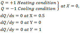
3. Numerical Validation
- The numerical method used to solve the governing equations (7-10) is the control-volume finite element method CVFEM. This method was historically introduced by Baliga & Patankar [29] for handling convection-diffusion problems. The discretization by the CVFEM allows to take six neighbouring points around each central point of the domain. The obtained discretised equation can be written in the following form:
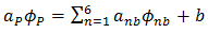 | (11) |
 is a general variable that can be
  . The total implicit scheme was used for the time discretization and the SIMPLER algorithm for the pressure-velocity coupling. The resulting algebraic system was solved by the TDMA line by line solver. The term Ck in the source terms of the momentum equations (8) and (9) corresponds to the enthalpy-porosity formulation defined by Brent & al. [28]:
 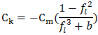 Where fl is the liquid fraction, Cm is a parameter depending on the morphology of the porous medium and is taken equal to 106; b=0.001 is introduced to avoid division by zero. To track the phase change front during the melting or the solidification, the update of the liquid fraction is determined by the following approach:
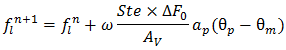 Where
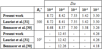
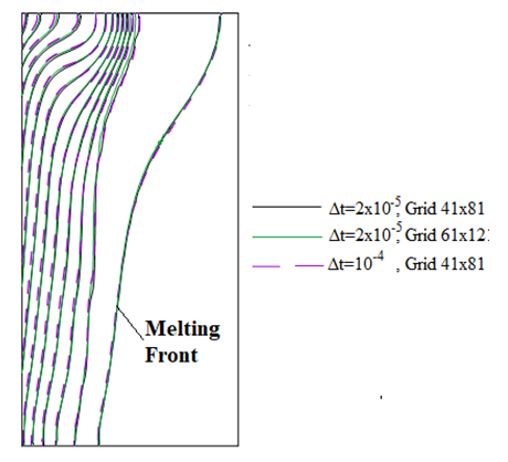
Where  is the area of the control volume, and is an under relaxation coefficient. The numerical method was first tested for the case of natural convection in a square enclosure, filled with a porous medium saturated with air, without considering the phase change. The vertical walls of the enclosure are subject to a horizontal temperature gradient while the bottom and the top walls are thermally insulated. The obtained results are presented in Table 1, in terms of average Nusselt number. Comparison with the numerical results obtained by Bennacer & al. [30] and Lauriat & al. [31] shows a good agreement. A second validation was performed to examine the capabilities of the numerical method to handle phase change problems. The numerical test consists of the melting of a pure metal (Gallium) in a square cavity of width L=8.89 cm and height H=0.635 cm. The left side of the cavity is subject to a hot temperature TH=38°C and the right wall is subject to a constant temperature 1°C below the melting temperature of the gallium Tm=28°C attempting to minimize subcooling effects. The horizontal walls are maintained adiabatic.
|
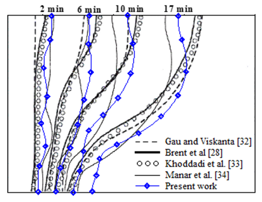 | Figure 2. Interface location at different times |
 | Figure 3. Isotherms at the dimensionless time τ=0.04 and the Melting front at τ=0.06 |
4. Numerical Results and Discussion
4.1. Effect of Thermal Conductivity Enhancement
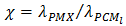
- The problem of melting inside a rectangular cavity heated by constant temperature on one vertical side and cooled on the opposite side has been extensively studied. In the present study, we consider the case where the cavity is heated by a uniform heat flux on one vertical side, while the opposite side is adiabatic. In addition, the study includes both melting and solidification inside a porous structure. The cavity is first subjected to a positive heat flux during a heating period τH. At the end of this period, a cooling stage starts, during which latent heat is extracted by solidification. To examine the effect of thermal conductivity enhancement, a simulation was first performed for a PCM-alone (n-octadecane) and then for a PCM embedded within a porous structure (Expanded Graphite). Thermophysical properties of n-octadecane and expanded graphite are listed in Table 2. Several dimensionless parameters govern the problem: the Rayleigh number Ra, the Prandtl number Pr, the Stefan number Ste, the porosity ε and the Darcy number Da. The parameter on which we focus in the present study is the ratio between the thermal conductivity of the material structure and the PCM (
 ). To ensure that the condition of thermal equilibrium between the solid matrix and the PCM will be satisfied, so a model of one equation can be used, intermediate values of χ have been considered (χ≈102). The dimensionless time was taken as the product of the Fourier and the Stefan numbers,
  which is a characteristic parameter for the time in the solid-liquid phase change problems.
|
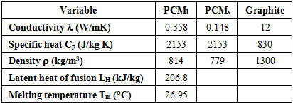
 for the PCM-EGR mixture, the shape of the isotherms shows that the melting is dominated by natural convection, also the liquid-solid front is more in advance compared to the case of pure PCM. At this same instant for the pure PCM, conduction heat transfer is still dominant, the isotherm lines are parallel and the liquid fraction thickness shows that the melting is progressed with a lower rate. At the dimensionless time τ=0.118, just before the end of the heating time (τH=0.12), for the PCM-EGR, the disappearance of the liquid-solid front and the shape of the isotherm lines indicate that the PCM is wholly turned into liquid. The acceleration of melting is then clearly apparent with the inclusion of the porous matrix. The isotherm values show also an increase of temperature of the storage medium which means that the melted domain is superheated. While for the pure PCM, the melting front is still at its early stage (Fig. 4-a).
  | Figure 4. Temperature contours and liquid-solid front for pure PCM (a) and PCM-EGR mixture (b) |
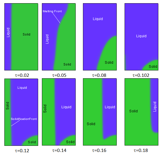
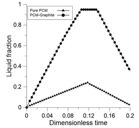 | Figure 5. Liquid fraction during melting and solidification |
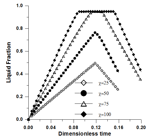 | Figure 6. Liquid fraction versus time. Effect of the thermal conductivity ratio. Ra=2x10⁶, Pr=50, Ste=0.1, ε=0.95 and Da=10-2 |
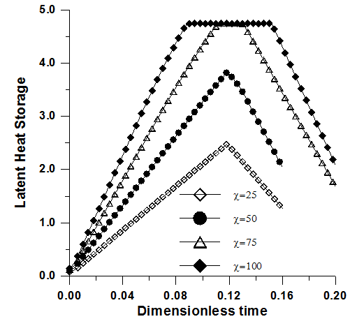 | Figure 7. Latent heat versus time. Effect of the thermal conductivity ratio. Ra=2x10⁶, Pr=50, Ste=0.1, ε=0.95, χ=75 and Da=10-2 |
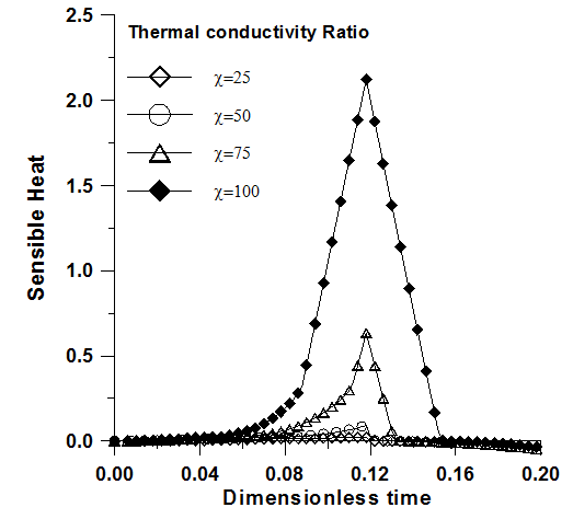 | Figure 8. Sensible heat versus time. Effect of the thermal conductivity ratio. Ra=2x10⁶, Pr=50, Ste=0.1, ε=0.95, χ=75 and Da=10-2 |
 | Figure 9. Liquid and solid fractions during the melting and solidification of a PCM-PMX composite. Ra=2x10⁶, Pr=50, Ste=0.1, ε=0.95, χ=75 and Da=10-2 |
4.2. Effect of the Heating Time
- To examine the effect of the heating period on the energy storage and recovery, the following parameters are maintained constant (Ra=2x10⁶, Pr=50, Ste=0.1, ε=0.95, Da=10-2 and χ=75) and the heating period is modified. Fig. 10 illustrates the latent heat fraction history for the heating periods τH=0.1, 0.12 and 0.13. For τH=0.1, the latent heat fraction doesn’t reach the maximum storage capacity and it starts to decrease immediately after the application of the cooling periods. For the heating periods τH=0.12 and τH=0.13, complete melting is achieved before the end of the heating time. The plots of the latent heat fraction show a stationary state (plateau) as mentioned earlier. During the stationary state, the absorbed heat is stored inside the medium in sensible form. Fig. 11 shows that the amount of sensible heat increases with the extension of the heating periods. This effect is generally undesirable in the heat storage system because the latent heat is much more important than the sensible heat storage.
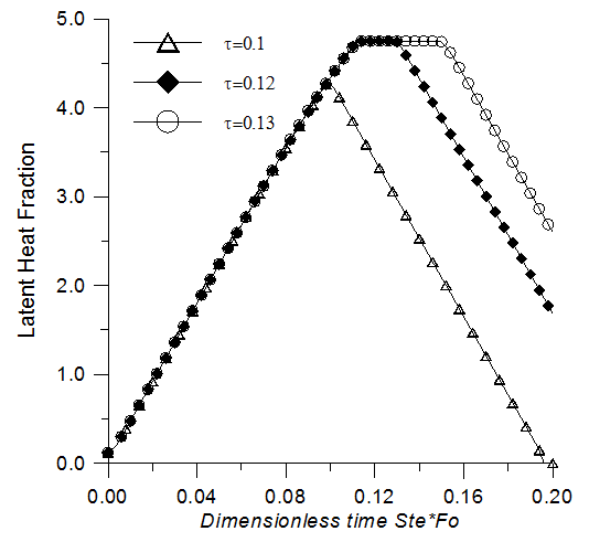 | Figure 10. Latent heat storage versus time, effect of the heating period |
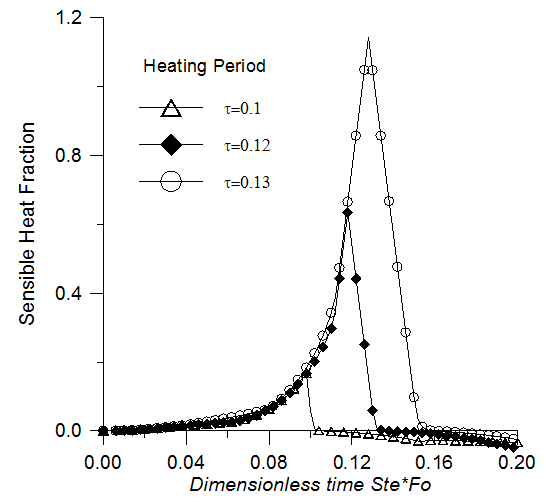 | Figure 11. Sensible heat storage versus time. Effect of the heating time |
5. Conclusions
- This paper presents a numerical investigation of the melting and solidification of a PCM embedded with a porous structure of high thermal conductivity. The enthalpy-porosity formulation and the thermal equilibrium approximation have been adopted in the problem modelling. It was found that the increase of the thermal conductivity contributes to the enhancement of the melting and solidification rates of the PCM and then the heat storage and recovery rates. It was also found that when the heating period exceeds the full melting time, the sensible heat storage will be increased. The growth of sensible heat storage during the charging period is a drawback because it causes the delay of solidification, then the recovery of latent heat, which is more targeted in heat storage systems because of its higher density.
ACKNOWLEDGEMENTS
- Authors are grateful to the King Abdul-Azizi City for Science and Technology (KACST) for supporting this research project.
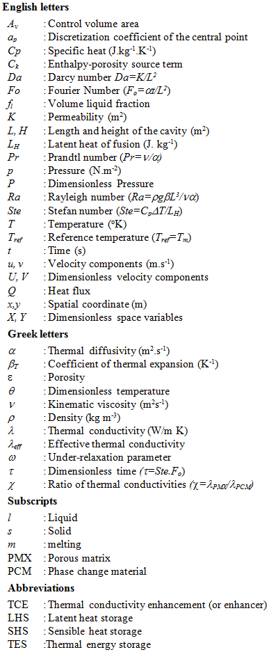
Nomenclature