-
Paper Information
- Paper Submission
-
Journal Information
- About This Journal
- Editorial Board
- Current Issue
- Archive
- Author Guidelines
- Contact Us
International Journal of Energy Engineering
p-ISSN: 2163-1891 e-ISSN: 2163-1905
2019; 9(1): 12-24
doi:10.5923/j.ijee.20190901.03

Numerical Study of an Exhaust Heat Recovery System Using Corrugated Tube Heat Exchanger with Modified Twisted Tape Inserts
 Abstract
 Reference
 Full-Text PDF
 Full-text HTML
Vamsi Mokkapati, Chuen-Sen Lin
Mechanical Engineering Department, University of Alaska Fairbanks, Fairbanks, AK, USA
Correspondence to: Chuen-Sen Lin, Mechanical Engineering Department, University of Alaska Fairbanks, Fairbanks, AK, USA.
| Email: |  |
Copyright © 2019 The Author(s). Published by Scientific & Academic Publishing.
This work is licensed under the Creative Commons Attribution International License (CC BY).
http://creativecommons.org/licenses/by/4.0/

In most rural villages in Alaska, power is generated by diesel generators and fossil fuels are burned for power and heating. Due to the extremely isolated conditions of most of these villages i.e., no road infrastructure, the costs of fuel, travel, system installation and maintenance (no technicians on-site) are very expensive. The primary goal of this work is to investigate gas-to-liquid heat transfer performance of a concentric tube heat exchanger with twisted tape inserted in corrugated tube and its modifications, and evaluate the impact on engine performance, economics, and reduced CO2 through exhaust heat recovery (exhaust contains 1/3 of energy of fuel consumed) of a heavy duty diesel generator (120ekW rated load), such as are being used in rural Alaska communities. This type of heat exchanger is expected to be inexpensive to install, require only minimal maintenance, and provide effective heat transfer, with minimal effect on exhaust emissions of diesel engines. Most previous research of corrugated concentric heat exchangers has investigated liquid-to-liquid or gas-to-gas heat transfer in corrugated tubes, not gas-to-liquid heat transfer. For this study, the SolidWorks Flow Simulation computer program is used. To validate program reliability, simulation results obtained through this software are compared with renowned correlations and field measurements. Simulations are then conducted for the corrugated concentric heat exchanger with twisted tape and its modifications to determine the optimal design. Twisted tape modifications include perforated twisted tape, dual twisted tape, twisted tape with cuts, serrated twisted tape, and twisted tape with rod. The maximum enhancement in the rate of heat transfer is found in an annularly corrugated tube heat exchanger, with a twisted tape with rod inserted. The enhancement is limited by the requirement of pressure drop constraint of the exhaust gas passing through the heat exchanger. This exchanger transfers about 279.3%, 126.17%, and 35.1% more heat compared to plain tube, annularly corrugated tube heat exchangers without twisted tapes, and annularly corrugated tube heat exchangers with plain twisted tape. Based on optimal results for a 120 kWe diesel generator, installing an annularly corrugated tube heat exchanger with a plain twisted tape insert can save 2,266 gallons of fuel annually; with a rod twisted tape insert, an annual savings of up to7622 gallons is attained. This is a savings of approximately 4252 gallons more than the presently installed heat recovery system can attain. In addition, CO2 emissions are reduced by up to 43 metric tons annually.
Keywords: Heavy duty diesel generator, Exhaust gas, Exhaust heat recovery, Concentric tube heat exchangers, Corrugated tube, Twisted tape with rod
Cite this paper: Vamsi Mokkapati, Chuen-Sen Lin, Numerical Study of an Exhaust Heat Recovery System Using Corrugated Tube Heat Exchanger with Modified Twisted Tape Inserts, International Journal of Energy Engineering, Vol. 9 No. 1, 2019, pp. 12-24. doi: 10.5923/j.ijee.20190901.03.
Article Outline
1. Introduction
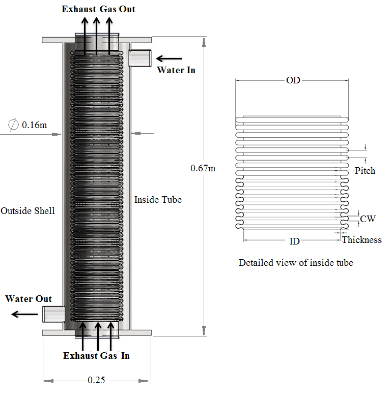
- Most small communities in cold regions use diesel generators for their major power supply and burn fossil fuels for both power generation and space heating. The heat dissipated into the atmosphere from diesel generator exhaust can amount to about one third of the fuel energy used. Normally, part of this heat can be captured with a heat exchanger (HEs), then used to help meet community heating and power needs. In Alaska, there are about 180 rural villages which have been using independent off-grid diesel generators for many decades, and most of them are not equipped with exhaust heat recovery systems. Because these villages are not on any road system and therefore very isolated, most of them do not have readily available or on-site maintenance technicians and engineers to address maintenance issues when they arise. Added to this are high shipping costs for parts and equipment and cumbersome and costly travel for technicians. A heat recovery system which can meet the needs of an efficient, low-cost, low-maintenance system is a vertically installed concentric tube heat exchanger (CHE) with a simple structure, which has been tested to capture the exhaust heat of a 120kW diesel generator (Figure 1) and no evidence has been found in fuel specific emissions and maintenance. The inner tube of this heat exchanger (HE) is for exhaust flow and is an annularly corrugated tube (ACT) rather than a plain tube, thereby providing a better heat transfer rate. The heat exchanger is installed vertically to reduce soot accumulation. The water exiting the engine jacket is further heated in the current heat recovery system and supplied for space heating. The advantages of using jacket water for heat recovery are an economical installation, no need for additional pumping power, and no extra thermodynamic loop costs. The purpose of this work is to further improve the effectiveness of heat recovery by using heat augmentation techniques. A literature review has been conducted on concentric tube heat exchangers (CHEs). The general geometry of a CHE is depicted in Figure 1. The inner tube can be of varying configurations, such as plain tube, corrugated tube (of various types), and corrugated tube with twisted tape insert (of various modifications). Plain tubes and corrugated tubes are widely used in heat transfer applications.Researchers conducted numerous experiments and numerical simulations on various CHEs using a wide range of corrugated tubes and twisted tapes individually to study liquid-to-liquid and air-to-air heat transfer performance, and proved that twisted tapes increase thermodynamic efficiency. Some of the work using different types of swirl generators was also covered in the literature review. The advantages of CHEs for engine exhaust heat recovery are the low cost and short pay-back period, less exhaust pressure drop, and minimal maintenance requirements for heat transfer surfaces that are exposed to corrosive or soot-forming fluids.Al-Fahed et al. [1] conducted experiments using oil as the working fluid for plain, micro-fin and twisted-tape insert tubes, and concluded that heat transfer increases with increased twist ratio. Saha et al. [2] investigated the effects of regularly spaced twisted tape elements in laminar and turbulent flow regimes, and reports that the heat transfer increased by 20-40%. Ray and Date [3] conducted numerical analysis by inserting a twisted tape in a square duct and developed correlations for friction factor and the Nusselt number. They report that there is a fair agreement between the simulated and experimental results. Garcia et al. [4] conducted an experimental study on heat transfer in a plain tube with wire coil inserts in laminar-transition-turbulent regimes and states that the heat transfer rate can be increased by up to 200%, keeping pumping power constant.Eiamsa-ard et al. [5] conducted experiments and report that the Nusselt number is improved by 160% over plain tube by using full-length twisted tape, and 179% by inserting helical tape with and without rods [7] inside the tube. Naphon and Sriromruln [6] conducted experiments by inserting coiled wire in plain tube and found that there is a significant effect of swirl in enhancing the rate of heat transfer.Chang et al. [8] investigated heat transfer experimentally in a tube with broken twisted tape inserts and report that thermal performance is improved by up to 0.9-1.8 times over those tubes fitted with smooth twisted tape. Heat transfer behavior with conical ring and twisted tape inserts was investigated experimentally by Promvonge and Eiamsa-ard [9], and they report a 367% enhancement in heat transfer over plain tube. Promvonge [10], states that heat transfer is enhanced about 1.2-1.3 times when square wire coil is inserted in a circular tube. Promvonge [11] conducted experiments to investigate air flow friction and heat transfer characteristics in a round tube fitted with both coiled wire and twisted tape, and obtained 200-350% enhancement in heat transfer.Bharadwaj et al. [12] conducted experiments on spirally grooved tube with twisted tape and report a 140% heat transfer enhancement over the plain tube. Rahimi et al. [13] also conducted numerical simulations with various twisted tapes, compared them to classical twisted tape, and observed an enhancement in the heat transfer coefficient of approximately 31%. Eiamsa-ard et al. [14] performed numerical simulations of swirling flow in circular tube with twisted tape and report that the mean heat transfer rates are about 73.6% higher than those of plain tube. Instead of changing the type of swirl-generating device, Thianpong et al. [15] changed the tube type and conducted experiments on a dimpled tube with classical twisted tape. They observed an enhancement of 1.66 to 3.03 times that of plain tube. Similarly, inserting twisted tapes in corrugated tube is expected to augment the generated swirl of plain tube and improve the rate of heat transfer.Mashoofi et al. [16] conducted a numerical study of the effect of axially perforated twisted tapes on the thermal performance enhancement of a double tube HE with plain tubes and found a reduction in pressure drop and heat transfer rate, compared to regular twisted tapes for high Reynolds numbers. Bahttacharyya et al. [17] performed a numerical investigation of heat transfer characteristics in a plain tube fitted with inserted twisted tapes. The investigation was done using a range of entrance angles of the twisted tapes and with various Reynolds numbers (100 to 20000), and found that higher entrance angles yield a higher heat transfer rate and pressure drop. Kurhade et al. [18] investigated heat transfer and friction factor properties experimentally using copper wavy twisted tape inserts in a plain inner tube of the HE, for a Reynolds number varying between 5000 and 17000. The investigation found that the Nusselt number value increased by 172% and the friction factor increased by 32.11%, compared to a tube without inserts. Prasad et al. [19] experimentally investigated the effects of applying AL2O3 nanofluid on the heat transfer rate and friction factor of a double tube HE. The investigation exhibited an enhancement in the heat transfer coefficient and friction factor, with an increase in volume concentration of the nanoparticle. Tamna et al. [20] conducted an experiment on heat transfer enhancement by inserting double-twisted tapes, together with 30° V-shaped ribs into a single pipe having a constant wall heat-flux with a Reynolds number from 5300 to 24000. Air is used as the test fluid flowing inside the pipe. The results show the increasing trend of Nusselt number and friction factor with the Reynolds number and relative rib height of the twisted tapes. Nanan et al. [21] experimentally investigated heat transfer enhancement by increasing helically twisted tapes to induce co- and counter-swirl flows (the corresponding tapes are symbolized as co-HTT and c-HTT) for fully developed turbulent flow, with a Reynolds number ranging between 6000 and 20000 under uniform wall heat flux conditions. Under similar conditions, the use of co-HTT results in a lower Nusselt number and friction factor but a higher thermal performance factor than that of c-HTT. The work also developed empirical correlations for Nusselt number, friction factor and thermal performance factor as functions of Reynold number, Prandtl number, and twisted tape pitch. Mokkapati and Lin [22] conducted a numerical study of an exhaust heat recovery system using an annularly corrugated tube heat exchanger with twisted tape inserts of various twist tape pitch, pitch ratio, and number of twists for a 120kW heavy duty diesel generator. The results showed that the heat exchanger can annually save 2250 gallons of fuel and $11,330 in fuel costs, and can reduce CO2 emissions by 23 metric tons annually. The expected payback period is about 1 month. Hasanpour et al. [23] studied heat transfer augmentation in perforated, V-cut, and U-cut twisted tapes experimentally and numerically and report that V-cut twisted tape enhances the Nusselt ratio about 2 times in a corrugated tube with plain twisted tape, while the lowest friction factor ratio with a perforated twisted tape had a range of 0.7-0.85. Nakhchi et al. [24] performed a numerical investigation on a rectangular-cut twisted tape insert and concluded that an increase in cut length ratio from 0.25 to 0.75 contributes to an increase in the Nusselt number by up to 33.26%. Shaojie Zhang et al. [25] evaluated the performance of a double-pipe heat exchanger fitted with self-rotating twisted tapes and plain twisted tape, and demonstrated that the rotating behavior of twisted tapes is another major factor for enhancing the heat transfer of heat exchanger tube with minor increase in the pressure drop. All the studies cited above, along with the present study, are summarized and presented in Table 1.
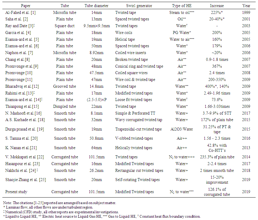 | Table 1. Related studies from the literature |
2. Diesel Exhaust Heat Recovery System
2.1. Current System
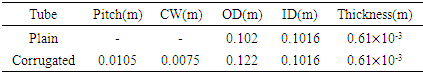
- The idea is tested in a power plant in Ruby, Alaska, using a vertically installed concentric tube heat exchanger with annularly corrugated tube as inner tube for exhaust. The outside tube is plain tube, with jacket water exiting the diesel engine jacket to capture exhaust heat for space heating. The heat recovery system is attached to a John Deere G4045-T300-HF458 Tier 3, 2010 model year, 1800RPM, 120ekW diesel generator (Fig. 1) [26]. The installation is proven to be retrofittable and inexpensive.
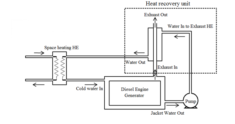 | Figure 1. Schematic diagram of the system |
|
 | Figure 2. Exhaust Heat Recovery Unit |
2.2. Proposed System to Improve Heat Transfer Performance
- The goal of the present work is to maximize the heat recovery rate by optimizing the design of the twisted tape. The controlled variables are the Reynolds number, ranging from 41,000 to 74,000 of exhaust. The constraints are the physical size of the heat exchanger, twist ratio, and exhaust back pressure change.
3. Annularly Corrugated Tube Heat Exchanger with Twisted Tape Inserts and Modified Twisted Tape Inserts
- To find ways to improve the heat transfer rate of the heat recovery system, a variety of twisted tapes inserted in the corrugated tube heat exchanger are investigated. The modifications need to be retrofittable and cost-effective. Their effect on emissions, maintenance, and pumping power must be negligible. Inserting twisted tape in the present heat recovery system has an almost negligible effect on all aspects mentioned earlier. The combined effect of the twisted tape and corrugations in the tube are expected to improve the swirls of exhaust and the rate of heat transfer. The above drawing represents a PTT, found to be the best configuration out of four types of PTTs [22]. Therefore, the modified twisted tapes (MTT) are designed with the same dimensions. To select the optimal MTT insert, 5 different MTT styles with different profiles are modeled and tested by being inserted into the ACT HE. The pitch (0.15m) of the twisted tape is inversely proportional to the number of twists (Fig. 3).
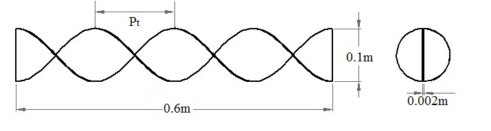 | Figure 3. Twisted tape dimensions |
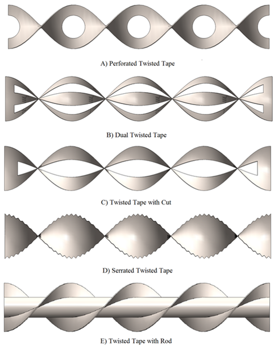 | Figure 4. Modified twisted tape swirl generators |
4. Mathematical Modelling
- Predicting the relationship between the heat transfer and swirling of the fluid inside the tubes is the main goal of the simulations. Figure 5 depicts simulations performed for an annularly corrugated tube (ACT) heat exchanger, both with various twisted tapes inserted and without. Included for reference is a simulation for a plain tube heat exchanger. The assumptions and boundary conditions for all simulations are listed below:
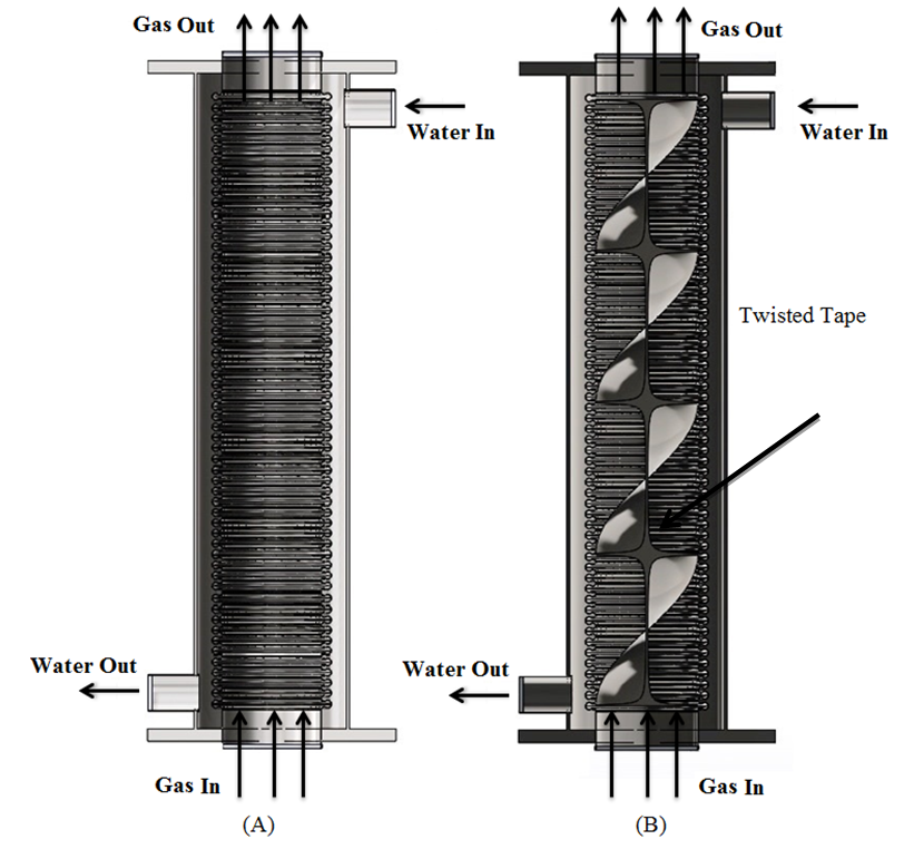 | Figure 5. Cross-sectional view of (A) ACT heat exchanger (B) ACT heat exchanger with twisted tape |
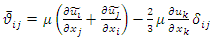
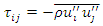
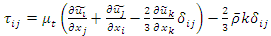
4.1. Governing Equations
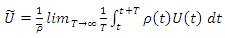
- The SolidWorks CFD package is used to perform the numerical analysis. The CFD package employs the Favre Averaged Navier Stokes (FANS) equations to model the velocity, pressure fields, and other aspects. For three-dimensional modelling, a combination of the law of conservations of mass, momentum and energy is used. The package is also suitable to use for highly turbulent flow cases [28], which is the density weighted time averaging Navier Stokes equation. • Classical time averaging for density and pressure, known as Reynolds averaging
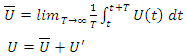 | (7) |
 | (8) |
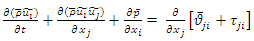
 T = Constant Time intervalFavre Averaged Navier Stokes (FANS) [29] equations, i.e., conservation equations can be written as follows:Continuity equation
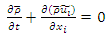 | (9) |
 | (10) |
 | (11) |
 | (12) |
 | (13) |
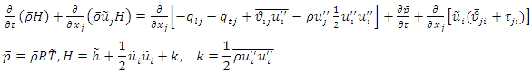 | (14) |
 = Static enthalpy, k = Turbulence kinetic energy,
  =Laminar heat flux vector and
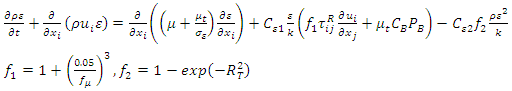
  = Turbulent heat flux vector. The k-ε turbulence model is used to model the turbulent regime for the present study.For turbulent kinetic energy (k)
 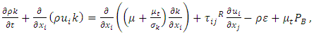 | (15) |

 | (16) |

 | (17) |
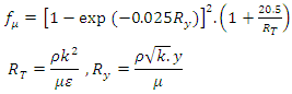
 are defined empirically.
4.2. Validation
- The numerical simulations are performed to validate the heat transfer coefficient obtained from simulations with the existing correlations for the Nusselt number. The agreement in the results of the experiment between the numerical analysis results and correlations results of Nusselt number values are within the 10% difference on the tube side. Fig. 6 shows the comparison between the numerical analysis, Dittous-Boelter’s correlation, Gnielinski’s correlation, and Petukhov’s correlation [27]. Dimensionless parameters use the Nusselt number (Nu), Reynolds number (Re), and Prandtl number (Pr).
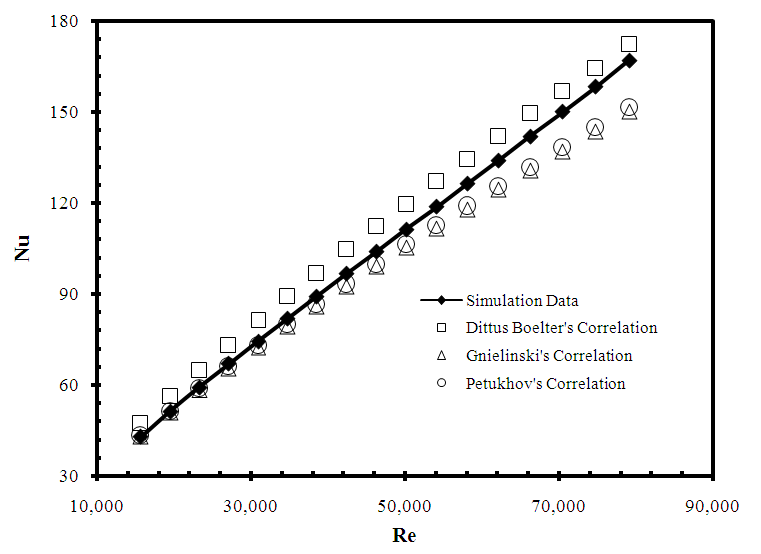 | Figure 6. Comparison of simulation results with existing correlation predictions |
- Nusselt number
 | (1) |
 | (2) |
 | (3) |
 | (4) |
 | (5) |
 Petukhov’s correlation
  | (6) |

4.3. Simulation Procedure
- The basic flow equations are derived using the finite volume method and following an integral approach. The conservative equations are discretized and solved throughout the model. The rate of increase in the quantity is equal to the sum of difference in the flux quantity and generation.
 | (18) |
4.4. Mesh Independent Study
- Three different meshes with total cells numbering 387705, 538467 and 924491 respectively are initially considered, and a mesh independent study is performed to verify the results. The results of heat transfer rate are compared and the discrepancies between the results are less than 0.5% (Fig. 7).
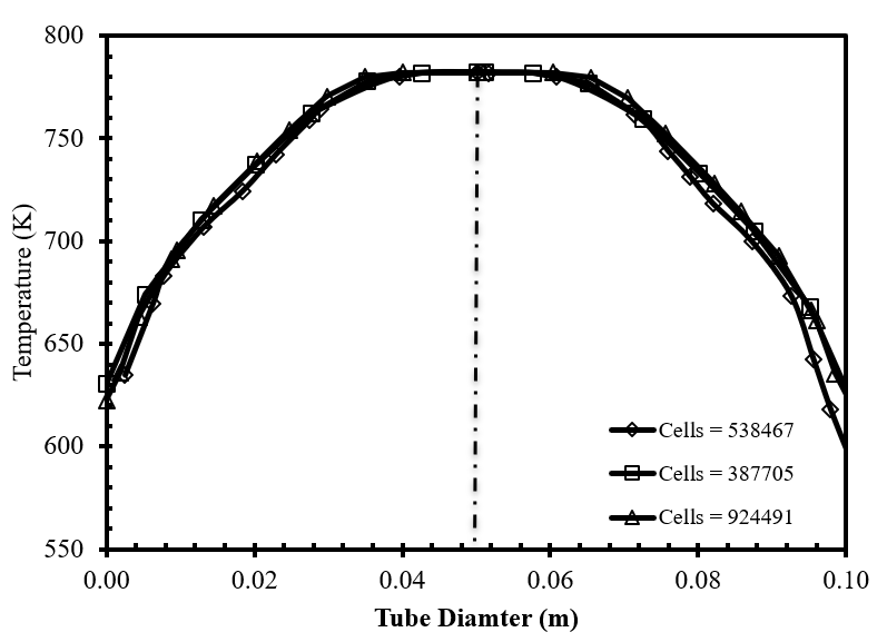 | Figure 7. Mesh Independent Study |
5. Numerical Simulations and Discussion of Results
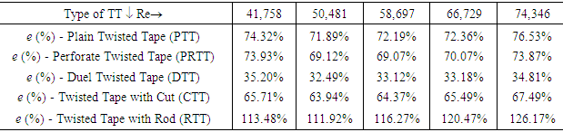
- To design the optimal modified twisted tape (MTT) for exhaust heat recovery application, simulations are conducted on the corrugated tube over a range of Reynolds numbers (Re) and with various types of MTT’s (see Fig. 4). The results are also compared to investigate enhancement in the heat transfer coefficient (Nu) and rate of heat transfer (Q). The Reynolds number range for the gas in the inner tube is from 41,758 to 74,346. Five styles of MTTs are designed for this study, each with a different profile, and each is expected to generate a different level of swirl. The graph in Figure 8 shows the simulation results for an ACTHE with modified twisted tapes, in terms of Nusselt number and Reynolds number. We can clearly see that the twisted tape with rod has the highest heat transfer coefficient.
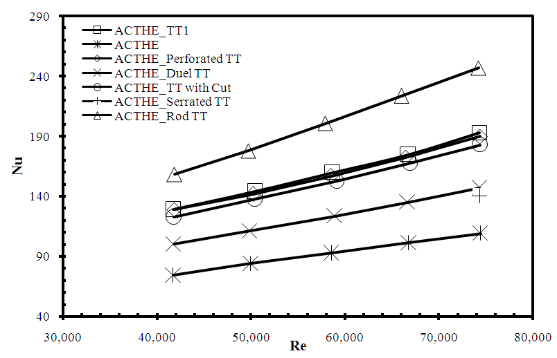 | Figure 8. Nusselt number versus Reynolds number for ACT and ACT with modified TTs |
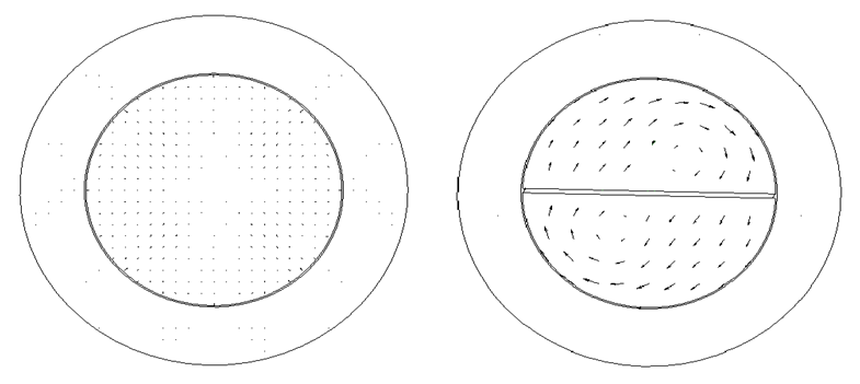 | Figure 9. Velocity vectors inside ACT and ACT with PTT at tube exit |
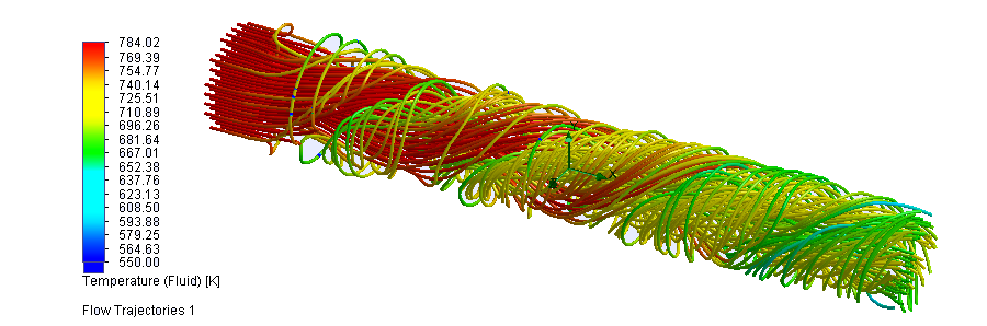 | Figure 10. Flow trajectories and temperature distribution of the gas inside ACT with PTT |
|
6. Economic Analysis
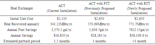
- In the village of Ruby, equipping the existing power plant diesel generator with ACT vertical HE would lead to a recovery of 11.48kW of heat from the diesel engine exhaust. The current cost of an ACT HE unit is $2,215; the approximated cost for the twisted tape with rod (RTT) is $500 (estimated by a local machine shop). Simulation results show that using RTT with a pitch of 0.15m can enhance the heat recovery rate by up to 126.17%.The cost of the twisted tape = $500The total system cost = $2,715 (i.e., unit cost + tape cost = $2,215 + $500)Heating value for the fuel at 75% boiler efficiency = 101,250 BTU/galTotal heat recovery rate of ACT HE = 11.48kW = 39,171.36BTU/hr Heat recovered per year = 39,171.36
 × 24
× 24  × 363
× 363  = 341.22MBTU/yrBased on a fuel cost of $5.00 per gallon, common for rural Alaska villages, the estimated payback period for an ACT heat exchanger with RTT is less than 1 month and requires practically no maintenance. The economic analysis is summarized in the first row of Table 4.
|
7. Conclusions
- A study to improve the effectiveness of a diesel exhaust heat recovery system (concentric tube heat exchanger) in the Ruby, Alaska diesel-fired power plant is conducted. The improved system consists of the original heat exchanger with a modified twisted tape inserted. The goal of the present work is to maximize the heat recovery rate by optimizing the design of the twisted tape insert with minor modifications. The physical size of the heat exchanger, twist ratio, and exhaust back pressure change are the constraints. In this study, the outer tube is a plain tube and the inner tube is an annularly corrugated tube with plain and modified twisted tape inserts. The following paragraphs summarize the findings of this study.1. The twisted tape insert is found to significantly improve heat transfer of the plain tube heat exchanger. Of all the twisted tape tested (TT1, TT2, TT3 and TT4), the lower pitch TT1 (also used as PTT ~0.15m) has the greatest effect on heat transfer enhancement, about 35.5%. This particular TT is modified and used for simulations in the corrugated tube. [22]2. The heat transfer rate in a corrugated tube heat exchanger with a twisted tape insert is 67% more than heat transfer in corrugated tube alone. When the same twisted tape is inserted into the plain tube heat exchanger, the heat transfer rate increases by approximately 35.3%. This clearly shows that corrugated tube promotes the effect of swirl over plain tube. [22]3. The corrugated tube heat exchanger with an MTT inserted has a significantly higher heat transfer rate than the corrugated tube with PTT. This is an improvement of about 126.17% in ACT with RTT, as compared to ACT, and 35.2% in ACT with RTT as compared to ACT with PTT.4. Using ACT HE with twisted tape can save up to 7622 gallons of fuel per year, a savings of 4252 gallons over that of the presently installed heat recovery system. Emissions of CO2 are reduced by up to 43 metric tons annually.5. The payback period for the proposed exhaust heat recovery system is less than 1 month, in comparison with the currently installed set-up, which is 1.5 months.6. The pressure drop of the exhaust gas in this heat recovery system is about 0.62psi (4.34kpa), showing that inserting twisted tape has minimal effect on engine performance.Based on this study, the proposed exhaust heat recovery system with RTT is simple, relatively inexpensive, easy to maintain, and has no practical effect on fuel specific exhaust emissions. In addition, it has a positive economic effect when applied to the Ruby diesel power plant. If this system were to be implemented in all diesel generators in rural Alaska villages, the potential effect could be a savings of up to $5.4 million annually, based on 370,000 MW-h power consumption in 2007 [32].
ACKNOWLEDGEMENTS
- The authors would like to gratefully acknowledge the support of Alaska Center for Energy and Power, Mechanical Engineering Department, College of Engineering and Mines at University of Alaska Fairbanks.
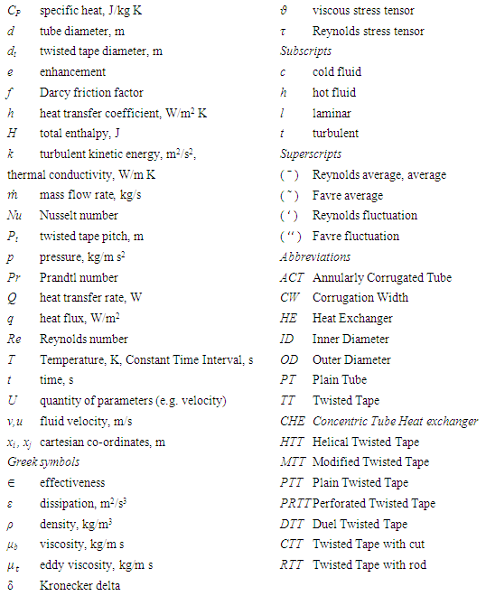
Nomenclature