-
Paper Information
- Paper Submission
-
Journal Information
- About This Journal
- Editorial Board
- Current Issue
- Archive
- Author Guidelines
- Contact Us
International Journal of Energy Engineering
p-ISSN: 2163-1891 e-ISSN: 2163-1905
2018; 8(4): 93-96
doi:10.5923/j.ijee.20180804.02

Enhancing 5G Patch Array Antenna Gain Using DNG Metamaterial
 Abstract
 Reference
 Full-Text PDF
 Full-text HTML
Hesham Wasel, Zhang Guoping
College of Physical Science and Technology, Central China Normal University, Wuhan, China
Correspondence to: Hesham Wasel, College of Physical Science and Technology, Central China Normal University, Wuhan, China.
| Email: |  |
Copyright © 2018 The Author(s). Published by Scientific & Academic Publishing.
This work is licensed under the Creative Commons Attribution International License (CC BY).
http://creativecommons.org/licenses/by/4.0/

This article investigates how to enhance the gain of an edge feed rectangular patch array antenna for 5G application using two novel double negative metamaterial (DNG). After designing a unit cell at same frequency (28 GHZ) to the patch array antenna, we scale the unit cell to 10x5 and 5x4. By placing these metamaterial structures at a distance of 6mm in front of the patch array antenna, the gain was significantly improved as compared to the conventional edge feed antenna without metamaterial. The DNG metamaterial has a complex shape on one side of dielectric medium and a wire on other side. The first metamaterial is composed of 2.5 mm × 2.5 mm FR-4 with 0.254 mm thickness and dielectric constant of 4.3 and the second design is composed of 3 mm x 3 mm Rogers RO4460 with 0.254 mm thickness and permittivity 6.15. The antenna consist of Rogers/RT5880 material with dielectric constant of 2.2. Scattering parameters as well as permittivity, permeability and refractive index are determined from the Simulation of DNG structure using Computer simulation technology (CST) in microwave studio (MWS). This is a novel and promising design approach in the world of 5G communication to enhance the gain of antenna due to its simplicity, compatibility and characteristics of double-negative material.
Keywords: Negative Permittivity, Negative Permeability, Resonators, Double negative (DNG) material, Negative Refractive Index
Cite this paper: Hesham Wasel, Zhang Guoping, Enhancing 5G Patch Array Antenna Gain Using DNG Metamaterial, International Journal of Energy Engineering, Vol. 8 No. 4, 2018, pp. 93-96. doi: 10.5923/j.ijee.20180804.02.
Article Outline
1. Introduction
- Metamaterials are artificially engineered materials that are designed to interact and control electromagnetic waves. In 1968, Victor Veselago first noted that materials that exhibit both negative permittivity and negative permeability simultaneously are called double-negative (DNG) metamaterials, materials [1]. Microstrip edge feed patch array antennas has low weight, low cost, easy to fabricate and integrated for 5G communication as well as other microwave devices [6]. Due to these advantages, microstrip edge feed patch array antennas can be used in mobile radio and wireless communication systems, radars, spacecraft, satellite, missile applications, etc. 5G antenna miniaturization will plays an important role in wireless communication systems. Although microstrip edge feed patch array antennas are of small thickness, their transverse dimension is in the order of half wavelength. Therefore, they are not small enough in their transverse dimension. Several different techniques have been proposed in order to reduce the size of the patch array antenna e.g. making slots in the patch [6] or using shorting posts [3]. Using a substrate with a high dielectric constant increases the flow of surface waves, which results in the gain reduction and deterioration of the radiation efficiency [5]. Also, the characteristic impedance in a high permittivity medium is rather low, so it causes difficulties in impedance matching. In order to deal with these problems and increase the gain of an antenna, metamaterial structures are used for miniaturization of the antenna. The primary electromagnetic properties of metamaterials are determined from the unit cell which is much smaller than wavelength. The constitutive parameters of metamaterials such as permittivity (ε) and permeability (μ) are used to explain their electromagnetic properties [9]. The first DNG metamaterial was fabricated experimentally by Smith and his colleague in UCSD [2]. Further researcher has proposed a rectangular “U-shaped” metamaterial Anik Mallik et al. [4], their findings exhibits double-negative characteristics at frequency range of 5, 6 and 11 GHz for different array configurations. This paper proposed DNG metamaterial combined with a patch array antenna which resonate at 28GHz suitable for 5G application. This was done by placing the DNG metamaterial structure in front of the patch at a small millimetre distance as the substrate is investigated, its return loss and radiation pattern were compared with the conventional patch antenna with the same dimension. The gain of the antenna was significantly increased from 9.9dB to 11.3 dB and 12.4 dB. Computer Simulation Technology (CST) Microwave Studio software was used to obtain the reflection and transmission parameters of the unit cell and to monitor the resonance frequency. These parameters obtained was used to determine the effective permeability (µ) and permittivity (ε) for the proposed configurations.
2. Design of DNG Metamaterial Unit Cell
- A schematic view and the design parameters of the proposed double-negative unit cell structure are presented in figure 1 and 2. The design of the structure is based on copper split resonators. CST Microwave studio was used to design double negative structure. A complex shape of copper having different length and height, but same width are used on dielectric medium (substrate) at the front, whereas a single rectangular wire of same length and width are used on other side of dielectric medium (back). The substrate used here is FR4 having a dielectric constant (εr) of 4.3 and the thickness of substrate is 0.254 mm. Figure 1 and 2 show our first and second structure of metamaterial unit cell respectively.
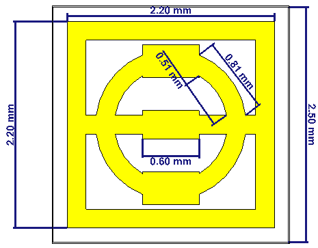 | Figure 1. Complex shape of metamaterial unit cell |
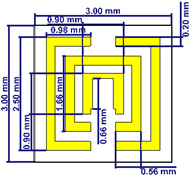 | Figure 2. Second design of metamaterial |
3. Results
- During the simulation process, the proposed DNG Metamaterial model is placed between two waveguide ports at both left and right of Y-axis. Port 1 is placed at positive Y-axis and Port 2 is towards negative Y-axis. The wave is excited from which we calculated the complex S11 (Transmission/reflection of port 1 to 1) and complex S21 (Transmission/ Reflection of port 1 to 2) parameters. The X-Plane is defined as a Perfect Electric Boundary (PEB) while Z-plane is defined as a Perfect Magnetic boundary (PMB).
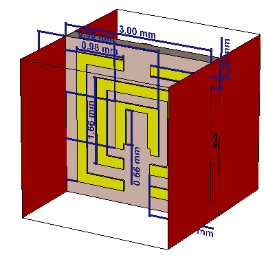 | Figure 3. Proposed metamaterial cell |
4. Results of Patch Array Antenna without Metamaterial
- In this part, we start to design a microstrip patch antenna array consist of two elements to increase the gain of antenna with minimum size and this array resonant at 28 GHz. The gain of the antenna is 9.9 dB. The range of frequency is between 27 to 29 GHz with minimum S11 value at 28 GHz equal to -45 dB. We can notice also the dimension of microstrip antenna in the figure 4.
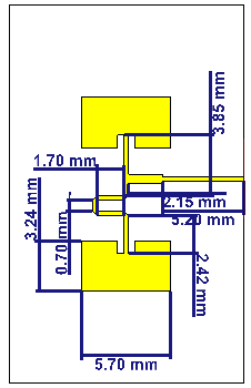 | Figure 4. Edge feed patch array antenna |
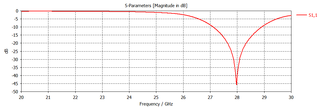 | Figure 5. S11 parameter of patch array antenna |
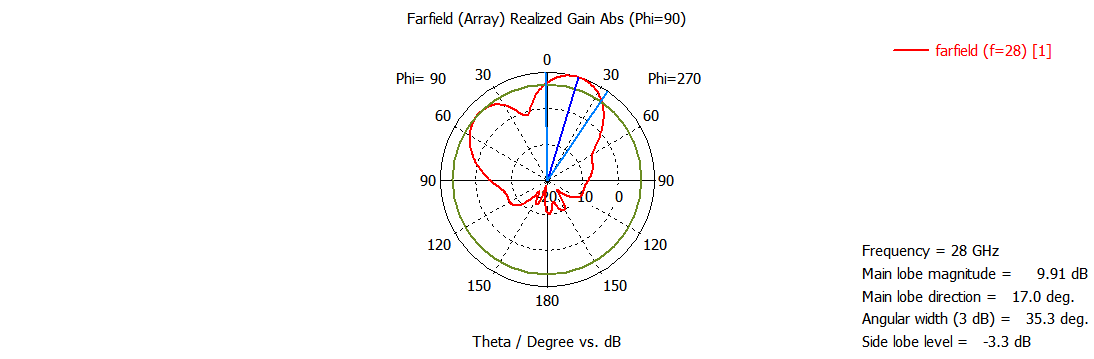 | Figure 6. Polar plot of patch array antenna |
5. Simulated Results of Patch Array Antenna with First Metamaterial Unite Cell
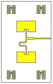
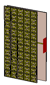 | Figure 7. Edge feed patch array antenna with Metamaterials |
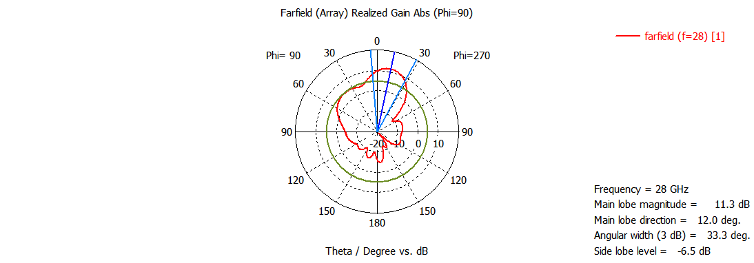 | Figure 8. Polar plot of patch array with metamaterial |
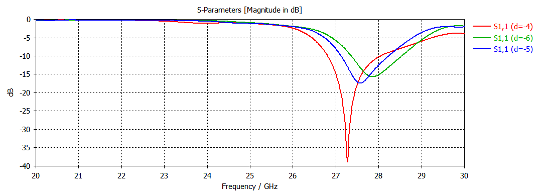 | Figure 9. S11 parameters for different distance d |
6. Second Design
- By using the second design of metamaterial, the gain increased from 9.9 to 12.4 dB. Figure 10 shows the structure of new design.Putting this structure on the patch array will increase the gain to 10.2 dB. Showing the structure in figure 10 and the result in figure 11.
 | Figure 10. Combination between patch array and metamaterial shape |
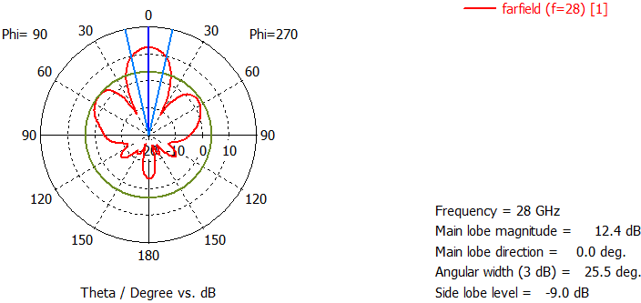
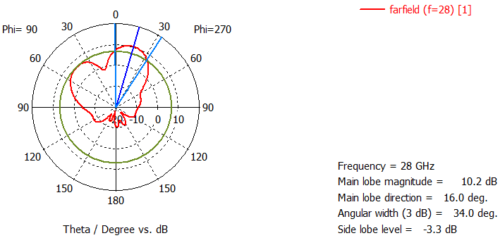 | Figure 11. Polar plot of combination shape |
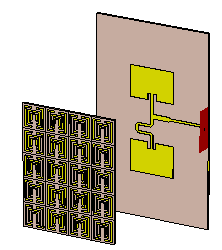 | Figure 12. Antenna model with metamaterial array |
 | Figure 13. Polar plot for the model |
7. Discussion
- Comparing the simulated values for return loss for the two DNG metamaterial shows a significant difference. From the simulation result of the antenna without metamaterial in figure 4, shows an impedance bandwidth from 27.1 to 28.9 GHz. However, the simulated results of the antenna with DNG metamaterial exhibits a much improved impedance bandwidth which depends on the distance between the antenna and metamaterial structure. This results shows that, the simulated antenna’s and radiation patterns, in the E and H planes at 28 GHz, shows variations in the far field gain of 12.4 dB and 9.9 dB for antenna with and without DNG metamaterial respectively. To enhance patch array antenna performance for 5G, it is important to understand the impact of the size of the DNG metamaterial unit cell structure serving as a lens on the radiation patterns and antenna performance [10]. To ensure the effect of the periodic structure size and to obtain the optimum return loss and radiation parameters, a parametric study on the antenna loaded with metamaterial lens at specific separation and different dimensions for the periodic structure are carried out [7-11]. Antenna gains are measured within the entire frequency band [10]. Comparing the two metamaterial design, one can notice that the second metamaterial shape has low number of unit cell with high gain and a better choices from the first one.
8. Conclusions
- At 28 GHz the simulated structure possesses simultenous negative permittivity and permeability having left handed properties. Findings from this research indicates that the unit cell structure can be used widely to improve diverse antenna gain for 5G. The combination of the DNG metamaterial unit cell structure with the patch array antenna has proof to enhance the gain and radiation of the antenna.From the two proposed double negative metamaterials, we recommend the second design to be the best choice to enhance a broad-bandwidth and high-gain of 12.4dB. The simulated design of the patch array antenna using the metamaterial concept has shown to have low loss, high gain and low voltage standing wave ratio.