M. Marouf Wani
Mechanical Engineering Department, National Institute of Technology, Srinagar, India
Correspondence to: M. Marouf Wani, Mechanical Engineering Department, National Institute of Technology, Srinagar, India.
| Email: |  |
Copyright © 2018 The Author(s). Published by Scientific & Academic Publishing.
This work is licensed under the Creative Commons Attribution International License (CC BY).
http://creativecommons.org/licenses/by/4.0/

Abstract
This paper presents the results of the computational research investigations, with design and operating parameters, for the possible turbo-charging of the conventional naturally aspirated multi-cylinder spark ignition engine used for medium load automotive applications. The computational thermodynamic investigations were done in the professional internal combustion engine simulation software AVL BOOST. The software solves the conservation equations for mass, energy and momentum for different components of the modeled engine using numerical methods. First the engine was modeled for its naturally aspirated version. The engine mapping, for this baseline engine, was done with the commercially available petrol and ethanol fuels. Next the engine was modeled for its turbocharged and intercooled version. The results were computed for the octane number requirements for both petrol and ethanol fuels for the turbocharged version of the engine to eliminate any possibility of knock. The results for the octane number requirements for petrol and ethanol were computed under variable speed and variable air-fuel ratio operation. The investigations were also done by changing the start of combustion timing which corresponds to optimization of new MBT timing for the turbocharged version of the engine with possible suitable fuels. It was observed from the results that the octane number of the commercial petrol has to be upgraded from 98 to 170 in order to use it in the turbocharged version of the spark ignition engine over its entire range of speed and load. It was also observed that octane number of commercial ethanol needs to be upgraded from 108 to 160 so that the engine could be run over its entire range of speed and load. This type of modifications in the engine design and the use of high octane number rated petrol and ethanol can boost the power of the petrol based engine by 140% and the ethanol based engine by 122%. The turbocharged version of the spark ignition engine operated with commercial ethanol fuel is possible for high speed applications only with normal combustion.
Keywords:
Turbo-charging, Spark Ignition Engine, Ethanol, Octane Requirement, Power Boosting, Downsizing
Cite this paper: M. Marouf Wani, Computational Thermodynamic Requirements for Possible Turbo-charging of a Spark Ignition Engine with Petrol and Ethanol Fuels, International Journal of Energy Engineering, Vol. 8 No. 3, 2018, pp. 53-61. doi: 10.5923/j.ijee.20180803.01.
1. Introduction
The concept of turbo-charging is used in the compression ignition engines for boosting its power or downsizing its displacement volume. This design modification helps in replacing the spark ignition engine by the economical compression ignition engine in automotives within the available bonnet space. While trying to adopt this technology for improving the design based performance characteristics of spark ignition engines it was observed that in order to have the knock free combustion with this category of engines the octane number of the commercial spark ignition engine fuels like petrol and ethanol should be increased.Heywood, in his authored text book, writes that attempts to boost the output of a given size spark ignition engine by an inlet air compression device that increases air pressure and temperature will aggravate the knock problem, since the end gas pressure and temperature will increase. However the higher output for a given displacement volume will decrease engine specific weight and volume. Also for the same maximum power, the smaller turbocharged engine should offer better fuel economy at part load. At a given part-load torque requirement, the mechanical efficiency (lower frictional loss) of the smaller turbocharged engine is higher. The variables that are adjusted to control knock in turbocharged SI engine are: compression ratio, spark retard from optimum, charge air temperature (inter-cooling), and fuel-air equivalence ratio. Most turbocharged SI engines now use a knock sensor and ignition-timing control system so that timing can be adjusted continuously to avoid knock without unnecessary retard. Turbo-charging the naturally aspirated 2.3-dm3 engine results in a 36 percent increase in maximum engine torque under certain conditions. In a vehicle context, the low-speed part-load advantage of the smaller size but equal power turbocharged engine should result in an average fuel economy benefit relative to the larger naturally aspirated engine. Knock is a phenomenon that is governed by both engine and fuel factors; its presence or absence in an engine depends on the antiknock quality of the fuel. [1]Indra F in his paper discusses the progress in the Development of Turbo-Charged Spark Ignition Engines for Passenger Cars. He observed that good results can be obtained with forced-induction engines incorporating four valves per cylinder. The most suitable applications are primarily in the performance car category, or for fast touring saloons.He further observed that the higher output levels necessitate the use of inter-cooling, sophisticated ignition and injection systems, heat resistant materials and more efficient cooling, all of which make turbo-charged engines more expensive. [2]Mohanan etal developed the computer simulation methodology for conducting the studies on a methanol fueled turbocharged multi-cylinder automotive spark ignition engine using the concepts of thermodynamics for evaluating its performance and emission characteristics. The computational studies were done with gasoline and methanol as two alternative fuels for two cases involving the original manifolds and the modified manifolds fitted with the turbocharger. The matching of the turbocharger with the engine was also studied. The results showed an increase in power output, lower nitrogen oxide and carbon monoxide emissions and improved brake specific energy consumption for the methanol fueled engine as compared to the gasoline version for both the original and modified engine designs operating on naturally aspirated and turbocharged conditions. The available experimental results validated the accuracy of the engine modeling based computational thermodynamic methodology. [3]Bromberg etal conducted experimental and computer simulation based research investigations for the octane requirement of a turbocharged spark ignition engine in various driving cycles under a wide range of speed and load. The methodology for the experiments involved the use of high octane PRF fuels and gasoline-ethanol blends after carefully defining the octane limits under different operating conditions. The above results were used for engine-in-vehicle simulations for calculation of the octane requirements of the models for a passenger car and a medium duty truck under various driving cycles. The authors also conducted the parametric studies for analyzing the effects of spark retard, engine downsizing at fixed vehicle performance, and vehicle types, on engine efficiency, fuel economy, and ethanol consumption. It was concluded that the high octane fuel (e.g., E85) effectively suppresses knock, but the octane ratings of such fuels are much above what is required under normal driving conditions. In view of above the authors further optimized the octane requirement of the engine itself over its full range of operation under each practical driving cycle for a turbocharged engine. The authors concluded that the average octane ratings of fuel needed in real-world driving were in the 60-80 RON range. The maximum RON required was 90-100. Downsizing and vehicle loading in trucks increased octane requirement substantially. Simulating the results for engine’s under required octane based fuels produced by varying the amount of ethanol in the mixture of a dual fuel system, it was observed that it can significantly increase the average engine brake efficiency (about 30% increase) and fuel economy (about 26%) depending on driving details. The above increased ethanol substitution could be brought down by retarding the spark timing by 5 crank angle degrees without compromising with the efficiency. [4]Bourhis etal conducted research investigations on a tubocharged spark ignition engine in a dual fuel mode to optimize the octane number requirement of the fuel by varying the fuel properties and the engine fuel injection parameters. The methodology involved the utilization of the concepts about knock in spark ignition engines that the efficiency of spark ignition engines is limited towards high loads by the occurrence of knock, which is linked to the octane number of the fuel. Further running the engine at its optimal efficiency requires a high octane number at high load, whereas a low octane number can be used at low load. The occurrence of knock can be avoided by adjusting the octane number (RON) of the fuel injected in the combustion chamber by developing the concept of “Octane on Demand” (OOD). The logic explained above will help to operate the engine which will practically have best possible thermal efficiency for each cycle at the corresponding operating load for that particular cycle. The above concept was implemented by a dual fuel injection strategy involving a low-RON base fuel and a high-RON octane booster. The ratio of fuel quantity on each injector is adapted to fit the RON requirement function of engine operating conditions. As per the authors this OOD concept entails a good characterization of the octane requirement needed to run the engine at its optimal efficiency over the entire map. To achieve the best fuel combination concept the authors performed the engine testing on direct and indirect injection multi-cylinder engine by using the fuel combinations involving three different octane boosters namely ethanol, reformate and a blend of butanol isomers (SuperButolTM)) with two base fuels namely a very low-RON naphtha-based fuel (RON 71) and a non-oxygenated gasoline (RON 91)). The above dual fuel injection based OOD concept was tested by using both GDI and PFI mixture preparation techniques. Results reveal that the injection configuration has quite a low effect on the octane booster demand (to keep the engine at its optimal combustion phasing). Ethanol is confirmed to be a remarkable octane booster, for its high latent heat of vaporization and its favorable sensitivity (defined as RON – MON). It is also shown that the base fuel, compared to the high octane fuel, has a weaker effect on the octane booster requirement, promoting the use of a less processed naphtha-based low-RON fuel (71) as a base fuel. 0D-simulation results, based on experimental data, reveal that a consumption around 25 %v/v of octane booster on the WLTP cycle is sufficient to keep the engine running on its optimal efficiency with a 71 RON base fuel. This leads to about 4% CO2 savings over the WLTP cycle (the more loaded the driving cycle, the larger the CO2 gains). [4]Amer etal conducted simulation tests on a single cylinder direct injection spark ignition (DISI) engine to investigate the effect of fuel properties, like octane number, on its knock characteristics under turbocharged conditions. In addition fuel effects on particulate emissions at part-throttle were measured. The methodology used involved the use of different fuels having RON in the range of 95 and 105. Different configurations of Turbochargers for raising the inlet air pressure up to 3.4 bar absolute were also used in simulating the results. The authors concluded that with the boosting levels tried in the investigations there is potential for downsizing a 3.2-liter engine to 1.5 liters using a 2-stage turbo-charger. The authors further conducted vehicle based simulations after incorporating the above engine based achievements and observed that it reduces the fuel consumption of the vehicle by 16% with the base fuel of 95 RON which increases up to 19% with a fuel of RON of 99.6. [5]Francesco Catapano etal. conducted experimental investigations to study the effects of air fuel mixing and combustion behavior of gasoline ethanol blends in a GDI wall guided turbocharged multi-cylinder optical engine. They observed that the addition of ethanol in gasoline allowed an improvement of engine performance in terms of IMEP, COV, IMEP and emissions. [6]Thiago etal conducted computer simulation studies on a turbocharged spark ignition engine using ethanol. The engine gave the satisfactory results. [7]Alberto etal conducted simulation studies on a directly injection turbocharged spark ignition ethanol engine. The results showed that the ethanol has higher knock resistance than petrol. Further it was concluded that the direct injection and turbo-charging are the key features of high efficiency and high power density ethanol engines [8].Jose etal conducted experimental investigations for exploring the limits of a downsized ethanol direct injection spark ignited engine in different configurations in order to replace high displacement gasoline engines. It was concluded that 28% of fuel consumption reduction was achieved by means of an extreme downsizing. 53% of downsizing was reached by using cutting edge technologies like using a twin stage compressor for achieving a larger pressure ratio. A significant decrease in the engine emissions was also achieved. [9]Hulser etal conducted investigations on the origin of pre-ignition in a highly boosted SI engine using biofuels namely tetrahydro2methylfuran (2MTHF) and 2methylfuran (2MF), in addition to the conventional ethanol and petrol fuels. The primary objective was to investigate the influence of molecular biofuel structure on the locations of preignition in a realistic, highly charged SI engine at low speed by state-of-the-art optical measurements. It was concluded that the pre-ignition tendency of these fuels decreases with increasing RON. Further as compared to other bio-fuels ethanol reveals a relatively high pre-ignition tendency, although its octane numbers (RON and MON) are particularly high. [10]Thewes etal conducted experimental investigations for analyzing the Effect of BioFuels on the Combustion in a Downsized DI SI Engine. In this study the fuel influence of several biofuel candidates on homogeneous engine combustion systems with direct injection is investigated.The results reveal Ethanol and 2Butanol are the two most knock resistant fuels. Hence these two fuels enable the highest efficiency improvements versus RON95 fuel ranging from 3.6% 12.7% for Ethanol as a result of a compression ratio increase of 5 units. Tetrahydro2methylfuran has a worse knock resistance and a decreased thermal efficiency due to the required reduction in compression ratio by 1.5 units. In general, 1Butanol and 2Butanol emit higher amounts of HC emissions in all operation points combined with significantly increased particle emissions at high loads indicating a worse mixture formation. [11]Zhang etal conducted experiments on the study of the lifecycle based optimized use of ethanol gasoline blends for turbocharged engines. The study involved a lifecycle (well to wheel) analysis to determine the CO2 emissions associated with ethanol blended gasoline in optimized turbocharged engines. The study involves a more accurate assessment on the best achievable CO2 emission of ethanol blended gasoline mixtures in future engines. The results showed that the engine downsizing technology can yield a CO2 reduction of up to 25.5% in a two stage downsized turbocharged engine burning the optimum sugarcane based fuel blend. [12]Baratta etal conducted experimental investigations on a 4 cylinder turbocharged spark ignition production engine to assess its performance and emissions with three fuels namely CNG and CNG/Hydrogen Blends (15% and 25% in volume of H₂). The methodology involved the modification of the engine into a dedicated CNG engine. The first part of the experimental investigations were carried out at MBT timing under stoichiometric conditions. The experiments were conducted at constant speed under variable load operation first followed by constant speed operation at variable load. Investigations were also conducted by varying the spark timings and relative air-fuel ratios and at the same time maintaining the speed and load constant. The cyclic and cylinder to cylinder variations were also investigated by recording pressure traces. It was concluded that the addition of hydrogen demands retarding the spark timing for developing maximum brake torque under stoichiometric conditions. The addition of hydrogen resulted in lowering the brake specific fuel consumption due to higher heating value of hydrogen. This ultimately increased the fuel conversion efficiency of the engine. There was reduction in total hydrocarbon emissions and CO emissions with increased substitution of hydrogen under duel fuel operation. However the NOx emissions were increased. The addition of hydrogen resulted in an increase in the lean operation limit of the engine with respect to CNG operation. There was significant cylinder-to-cylinder variations with all the fuels under consideration due to non uniform spatial distribution of fuels among various cylinders which in turn affects the effectiveness of the cooling system and the uniform air/fuel mixture distribution. [13]
2. Theoretical Basis [14]
2.1. The Cylinder, High Pressure Cycle, Basic Equation
The calculation of the high pressure cycle of an internal combustion engine is based on the first law of thermodynamics: | (1) |
where = change of the internal energy in the cylinder.
 = piston work.
 = fuel heat input.
 = wall heat losses
 = enthalpy flow due to blow-by
 = blow-by mass flowThe first law of thermodynamics for high pressure cycle states that the change of internal energy in the cylinder is equal to the sum of piston work, fuel heat input, wall heat losses and the enthalpy flow due to blow-by.In order to solve this equation, models for the combustion process and the wall heat transfer, as well as the gas properties as a function of pressure, temperature, and gas composition are required.Together with the gas equation
 | (2) |
Establishing the relation between pressure, temperature and density, Eq. 2 for in-cylinder temperature can be solved using a Runge-Kutta method. Once the cylinder gas temperature is known, the cylinder gas pressure can be obtained from the gas equation.
2.2. Combustion Model
2.2.1. Air Requirement and Heating Value Stoichiometric Air-Fuel Mixture
The following equation for the stoichiometric air requirement specifies how much air is required for a complete combustion of 1 kg fuel: | (3) |
2.2.2. Lean Mixture
For lean combustion, the total heat supplied during the cycle can be calculated from the amount of fuel in the cylinder and the lower heating value of the fuel.
2.2.3. Rich Mixture
In rich air fuel mixture combustion, the total heat supplied during the cycle is limited by the amount of air in the cylinder. The fuel is totally converted to combustion products even if the amount of air available is less than the amount of stoichiometric air.
2.2.4. Heating Value
The lower heating value is a fuel property and can be calculated from the following formula: | (4) |
2.3. Heat Release Approach
2.3.1. Vibe Two Zone
The rate of heat release and mass fraction burned is specified by the Vibe function given by equation No.5 below.The first law of thermodynamics is applied separately to the burned and unburned mixture while assuming that the temperatures of these two mixtures is different. | (5) |
 | (6) |
 | (7) |
The integral of the vibe function gives the fraction of the fuel mass which was burned since the start of combustion: | (8) |
2.4. Gas Exchange Process, Basic Equation
The equation for the simulation of the gas exchange process is also the first law of thermodynamics: | (9) |
The variation of the mass in the cylinder can be calculated from the sum of the in-flowing and out-flowing masses: | (10) |
2.5. Piston Motion
Piston motion applies to both the high pressure cycle and the gas exchange process.For a standard crank train the piston motion as a function of the crank angle α can be written as: | (11) |
 | (12) |
2.6. Heat Transfer
The heat transfer to the walls of the combustion chamber, i.e. the cylinder head, the piston, and the cylinder liner, is calculated from: | (13) |
In the case of the liner wall temperature, the axial temperature variation between the piston TDC and BDC position is taken into account: | (14) |
 | (15) |
For the calculation of the heat transfer coefficient, the Woschni 1978 heat transfer model is used.
2.7. Woschni Model
The woschni model published in 1978 for the high pressure cycle is summarized as follows: | (16) |
C1 = 2.28+0.308.cu/cmC2 = 0.00324 for DI enginesFor the gas exchange process, the heat transfer coefficient is given by following equation: | (17) |
C3 = 6.18+0.417.cu/cm.
2.8. Fuel Injector
The fuel injector model is based on the calculation algorithm of the flow restriction. This means that the air flow rate in the fuel injector depends on the pressure difference across the injector and is calculated using the specified flow coefficients.For the injector model, a measuring point must be specified at the location of the air flow meter. In this case the mean air flow at the air flow meter location during the last complete cycle is used to determine the amount of fuel. As is the case for continuous fuel injection, the fuelling rate is constant over crank angle.
2.9. Pipe Flow
The one dimensional gas dynamics in a pipe are described by the continuity equation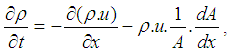 | (18) |
the equation for the conservation of momentum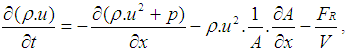 | (19) |
and by the energy equation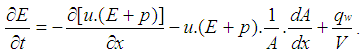 | (20) |
The wall friction force can be determined from the wall friction factor  :
: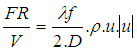 | (21) |
Using the Reynold’s analogy, the wall heat flow in the pipe can be calculated from the friction force and the difference between wall temperature and gas temperature: | (22) |
During the course of numerical integration of the conservation laws defined in the Eq.20, Eq.21 and Eq.22, special attention should be focused on the control of the time step. In order to achieve a stable solution, the CFL criterion (stability criterion defined by Courant, Friedrichs and Lewy) must be met: | (23) |
This means that a certain relation between the time step and the lengths of the cells must be met. The time step to cell size relation is determined at the beginning of the calculation on the basis of the specified initial conditions in the pipes. However, the CFL criterion is checked every time step during the calculation. If the criterion is not met because of significantly changed flow conditions in the pipes, the time step is reduced automatically.An ENO scheme is used for the solution of the set of non-linear differential equations discussed above. The ENO scheme is based on a finite volume approach. This means that the solution at the end of the time step is obtained from the value at the beginning of the time step and from the fluxes over the cell borders.
2.10. Knock Model
2.10.1. Ignition Delay and Octane Number Requirement
AVL Boost uses the following equation based model proposed by Hires etal. for the calculation of ignition delay in combustion. | (24) |
where τiD = ignition delayON = Octane Number RequirementA = 17.68 msB = 3800 Ka = 3.402n = 1.7
3. Results and Discussions
3.1. Effect of Speed on Octane Requirement
The Fig.1 below shows the effect of speed on the octane demand of the spark ignition engine under turbocharged conditions. It is seen that the octane number requirement for both the fuels petrol and ethanol is highest at lower speed and decreases with increase in speed.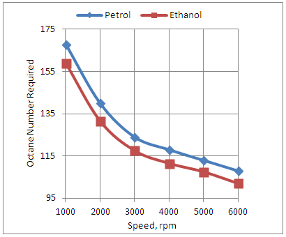 | Figure 1. Effect of Speed on Octane Number Requirement |
It is seen further that in order to boost power from a spark ignition engine by using a turbocharger, the octane number of commercial petrol upgraded from 98 to 170 and similarly the octane number of commercial ethanol has to be upgraded from 108 to 160.But these two changes in the octane numbers of petrol and ethanol could result in a minimum of 140% increase in power output of the petrol engine and a minimum of 122% increase in the power output of the ethanol based engine when compared with the naturally aspirated versions of the same engine being operated with the corresponding fuels.This also means that for the same baseline power output, as produced by the naturally aspirated version of the spark ignition engine under consideration, the displacement volume required for the turbocharged version will be reduced to its half approximately.
3.2. Effect of Spark Timing on Octane Number Requirement
The Fig.2. below shows the effect of start of combustion timing on the octane demand of the turbocharged spark ignition engine for both petrol and ethanol fuels. The start of combustion timing corresponds to the spark timing of the engine in both the cases after including a delay period in it. It is seen that the octane demand of the engine with both petrol and ethanol increases with advancing the start of combustion timing. It is clear from the graphs that the octane number of both commercially available petrol and ethanol need to be upgraded if the spark timing of the turbocharged engine under consideration is advanced.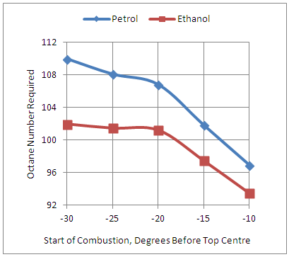 | Figure 2. Effect of Start of Combustion on Octane Number Requirement |
3.3. Effect of Air-Fuel Ratio on Octane Number Requirement
The Fig.3 below shows the effect of air-fuel ratio, which corresponds to constant speed and variable load operation, on the octane demand of the turbocharged spark ignition engine.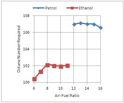 | Figure 3. Effect of Air-Fuel Ratio on Octane Number Requirement |
It is seen from the graph that at the operating speed of 6000rpm, the turbocharged version of the spark ignition engine can be operated over its entire range of load with the commercially available ethanol having octane number of 108.The turbocharged engine can run successfully over its entire range of load or air-fuel ratio for both the fuels petrol and ethanol with the octane number ratings of 170 and 160 respectively as computed earlier with variable speed operation.
3.4. Effect of Optimizing the Spark Timing on Engine Power Output
The Fig.4 below shows the effect of start of combustion timing, which corresponds to the spark timing of the engine with a certain delay period, on the power output of the turbocharged spark ignition engine. It is clear from the graph that the spark timing corresponding to the maximum brake torque timing, has to be optimized again for the turbocharged version of the spark ignition engine in order to take full advantage of the high octane number rated petrol and ethanol used for the turbocharged version of the engine under consideration. Also the optimized maximum brake torque timing gets advanced with the high octane number based petrol and ethanol for the turbocharged engine as compared to its naturally aspirated version. As seen from the graph this also results in further increase in power output of the turbocharged engine.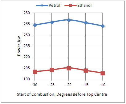 | Figure 4. Effect of Start of Combustion on Power |
4. Conclusions
1. The results suggest that a turbocharged spark ignition engine operated with ethanol fuel can be used for high speed applications only. This is possible if the engine is operated in its turbocharged version at speeds higher than 4000rpm with ethanol as its fuel. At lower speeds the turbocharger has to be bypassed by the exhaust gas moving out of the engine by using an arrangement like a waste gate system. In other words at speeds below 4000rpm the engine has to be operated as a naturally aspirated engine.2. The turbocharged multi-cylinder spark ignition engines can be used as an alternative technology for diesel based turbocharged compression ignition engines within the limitations as mentioned in conclusion at S.No1. 3. For example, at present the turbocharged diesel passenger car engine of about 100Kw power output operate at about 4200rpm because of inertia loads involved with its design. [15] But if these are replaced by the turbocharged spark ignition engines to be operated with ethanol fuel the rated speed can successfully go up to 5500rpm because the design based inherent inertia loads are much lower with spark ignition engines as compared to compression ignition engines. 4. Also a petrol based 1.7 litres spark ignition engine producing a power of 100Kw and used for small sports car applications is operated at a speed of 7200rpm, which is already a speed on higher side. [15]The turbocharged version of the same engine when operated with ethanol fuel under similar high engine operating speed conditions will help to downsize its displacement volume required by about 4-5%.
ACKNOWLEDGEMENTS
Author is thankful to AVL Austria and its unit AVL India Ltd Gurgaon for providing BOOST engine simulation software with free license for academic purposes.
Appendix-A
Nomenclaturea = speed of soundA = pipe cross-sectionAeff = effective flow areaAi = surface area (cylinder head, piston, liner)AFCP = air fuel ratio of combustion productsAgeo = geometrical flow areac = mass fraction of carbon in the fuelcV = specific heat at constant volumecp = specific heat at constant pressureC1 = 2.28+0.308.cu/cmC2 = 0.00324 for DI enginesCm = mean piston speedCu = circumferential velocitycu = circumferential velocityD = cylinder boreD = pipe diameterdmi = mass element flowing into the cylinderdme = mass element flowing out of the cylinderdvi = inner valve seat diameter (reference diameter) = blow-by mass flowe = piston pin offsetE = energy content of the gas
 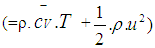 f = fraction of evaporation heat from the cylinder chargeFR = wall friction forceh = mass fraction of hydrogen in the fuelhBB = enthalpy of blow-byhi = enthalpy of in-flowing masshe = enthalpy of the mass leaving the cylinderHu = lower heating valuek = ratio of specific heatsl = con-rod lengthm = shape factor
 = mass flow ratemc = mass in the cylindermev = evaporating fuelmpl = mass in the plenumn = mass fraction of nitrogen in the fuelo = mass fraction of oxygen in the fuelp = static pressureP01 = upstream stagnation pressurePc,o = cylinder pressure of the motored engine[bar]Pc,1 = pressure in the cylinder at IVC[bar]ppl = pressure in the plenumpc = cylinder pressurep2 = downstream static pressureqev = evaporation heat of the fuelqw = wall heat flowQ = total fuel heat inputQF = fuel energyQwi = wall heat flow (cylinder head, piston, liner)r = crank radiusR0 = gas constants = piston distance from TDCt = timeT = temperatureTc,1 = temperature in the cylinder at intake valve closing (IVC)Tc = gas temperature in the cylinderTwi = wall temperature (cylinder head, piston, liner)TL = liner temperatureTL,TDC= liner temperature at TDC positionTL,BDC= liner temperature at BDC positionTw = pipe wall temperatureT01 = upstream stagnation temperatureu = specific internal energyu = flow velocityV = cylinder volumeV = cell volume (A.dx)VD = displacement per cylinderw = mass fraction of water in the fuelx = relative stroke (actual piston position related to full stroke)x = coordinate along the pipe axisα = crank angleαo = start of combustionΔαc = combustion durationαw = heat transfer coefficientρ = densityμσ = flow coefficient of the portψ = crank angle between vertical crank position and piston TDC position
 =wall friction coefficientΔt = time stepΔx = cell length
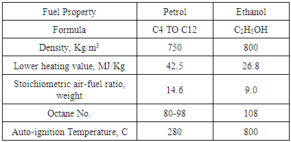
Table 1. Physical and Chemical Properties of Petrol and Ethanol [16]
 |
| |
|
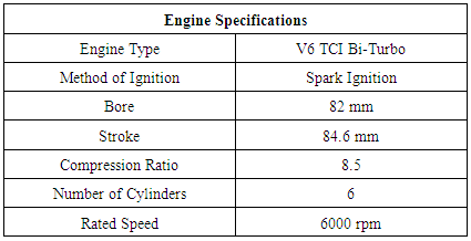
Table 2
 |
| |
|
References
| [1] | Heywood John B., “Fundamentals of internal combustion engines” McGraw Hill International Publication, 1989. |
| [2] | Indra, F., "Progress In The Development Of Turbo-Charged Spark Ignition Engines For Passenger Cars," SAE Technical Paper 845041, 1984. |
| [3] | Mohanan, P. and Gajendra Babu, M., "A Simulation Model for a Methanol Fueled Turbocharged Multi-Cylinder Automotive Spark Ignition Engine," SAE Technical Paper 912417, 1991. |
| [4] | Jo, Y., Bromberg, L., and Heywood, J., "Octane Requirement of a Turbocharged Spark Ignition Engine in Various Driving Cycles," SAE Technical Paper 2016-01-0831, 2016. |
| [5] | G. Bourhis; J.P. Solari; R. Dauphin and L. D. Francqueville “Fuel Properties and Engine Injection Configuration Effects on the Octane on Demand Concept for a Dual Fuel Turbocharged Spark Ignition Engine.” SAE Technical Paper 2016-01-2307, 2016. |
| [6] | Francesco Catapano, Paolo Sementa, Bianca Maria Vaglieco, “Air fuel mixing and combustion behavior of gasoline ethanol blends in a GDI wall guided turbocharged multi-cylinder optical engine”, Elsevier journal of Renewal Energy, Volume 96, Part A, October 2016. |
| [7] | Vieira, T., Baeta, J., and Sodré, J., "Computer Simulation of Turbocharged SI Engine Running on Ethanol," SAE Technical Paper 2014-36-0366, 2014. |
| [8] | Alberto Boretti, “Towards 40% efficiency with BMEP exceeding 30 bar in directly injected, turbocharged, spark ignition ethanol engines”, Elsevier journal of Energy Conversion and Management, Volume 57, May 2012. |
| [9] | José Guilherme Coelho Baêtaa, Michael Pontoppidanb, Thiago R.V. Silvaa, “Exploring the limits of a downsized ethanol direct injection spark ignited engine in different configurations in order to replace high displacement gasoline engines”, Elsevier journal of Energy Conversion and Management, Volume 105, 15 November, 2015. |
| [10] | Hülser, T., Grünefeld, G., Brands, T., Günther, M. et al., "Optical Investigation on the Origin of PreIgnition in a Highly Boosted SI Engine Using BioFuels," SAE Technical Paper 2013-01-1636, 2013. |
| [11] | Thewes, M., Muther, M., Brassat, A., Pischinger, S. et al., "Analysis of the Effect of BioFuels on the Combustion in a Downsized DI SI Engine," SAE Int. J. Fuels Lubr. (1):274288, 2012, doi:10.4271/2011-01-1991. |
| [12] | Bo Zhang, S. Mani Sarathy, “Lifecycle optimized ethanol gasoline blends for turbocharged engines”, Elsevier journal of Applied Energy, Volume 181, 1 November, 2016. |
| [13] | Baratta, M., D'Ambrosio, S., and Misul, D., "Performance and Emissions of a Turbocharged Spark Ignition Engine Fuelled with CNG and CNG/Hydrogen Blends," SAE Technical Paper 2013-01-0866, 2013. |
| [14] | AVL LIST Gmbh, AVL BOOST Theory, Version 2009.1. |
| [15] | Hoag Kevin L., “Vehicular Engine Design” SAE International Publication. |
| [16] | Richard Bechtold, “Alternative Fuels Guide Book”, SAE International Publication. |

 Abstract
 Reference
 Full-Text PDF
 Full-text HTML