-
Paper Information
- Previous Paper
- Paper Submission
-
Journal Information
- About This Journal
- Editorial Board
- Current Issue
- Archive
- Author Guidelines
- Contact Us
International Journal of Energy Engineering
p-ISSN: 2163-1891 e-ISSN: 2163-1905
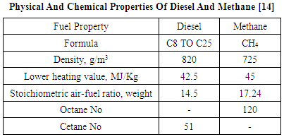
2018; 8(2): 30-39
doi:10.5923/j.ijee.20180802.02

Thermodynamic Potential for Reducing the GHG (CO2) Emissions from a TCI CI Engine by Using Methane 80% and Diesel 20% in the Dual Fuel Mode
 Abstract
 Reference
 Full-Text PDF
 Full-text HTML
M. Marouf Wani
Mechanical Engineering Department, National Institute of Technology, J&K, Srinagar, India
Correspondence to: M. Marouf Wani, Mechanical Engineering Department, National Institute of Technology, J&K, Srinagar, India.
| Email: |  |
This work is licensed under the Creative Commons Attribution International License (CC BY).
http://creativecommons.org/licenses/by/4.0/

This paper presents the results of computational research investigations on the thermodynamic potential of green house gas (GHG - CO2) emissions reduction from a 6 cylinder TCI diesel engine used for medium duty automotive applications by using methane 80% and diesel 20% as an alternative fuel to conventional neat diesel. Methane was used as a replacement for the commercially available CNG having physical and chemical properties very close to it. The results were computed in the professional thermodynamic internal combustion engines simulation software AVL BOOST. The software has been designed by coding the conservation laws for mass, energy and momentum for engine as an open and closed thermodynamic system. The 1-Dimensional Navier Stokes equation known as momentum equation is solved by using the numerical finite volume method (FVM). The results were first generated for the engine in the neat diesel mode. Next the simulations were repeated with methane 80% and diesel 20% dual fuel mode operation. The methane is supplied along with air and the combustion is initiated with 20% diesel injected directly into the engine cylinder. The results showed that the GHG emissions were reduced by about 35.8% at 1000rpm to about 36.57% at 4000rpm. in the methane 80% and diesel 20% dual fuel mode operation as compared to the neat diesel operation. Also the mass fraction of the GHG emissions in the exhaust gas was reduced by about 6.66% in the methane 80% and diesel 20% dual fuel mode as compared to the neat diesel fuel mode.
Keywords: GHG, Engine, Diesel, Methane
Cite this paper: M. Marouf Wani, Thermodynamic Potential for Reducing the GHG (CO2) Emissions from a TCI CI Engine by Using Methane 80% and Diesel 20% in the Dual Fuel Mode, International Journal of Energy Engineering, Vol. 8 No. 2, 2018, pp. 30-39. doi: 10.5923/j.ijee.20180802.02.
Article Outline
1. Introduction
- The emissions from the compression ignition engines with neat diesel and methane 80% and diesel 20% dual fuel modes are GHG (CO2), CO, Soot and NOx. The concentration of these pollutants from the internal combustion engines depends upon the engine design and operating conditions. The changes in the engine operating conditions from the rich mixture side to the stoichiometric mixture and further towards the leaner operation of the engine also changes the concentration of pollutants from the engines. As seen from the combustion based chemical equations the maximum GHG emissions will be produced from engines under stoichiometric combustion conditions. As we use rich mixtures the CO and HC emissions increase with a possible increase in the power and torque output also. Again using leaner mixtures the CO and HC emissions are reduced. The NOx emissions produced from the nitrogen and the oxygen of the air are highest near the stoichiometric mixture conditions and drop down towards both rich as well as the lean side of the mixture. In order to design engines suitable for present and future emissions regulations additional thermodynamic devices like catalyst are used. The pollutants like CO and HC need oxidation type of catalytic convertor while as the pollutants like NO and NO2 (NOx) need reduction type of catalytic convertor. Since almost all of these pollutants are present in the exhaust gas of the engine, a combination of oxidation and reduction known as the Redox type of a catalyst is used in exhaust gas manifolds of engines. The NOx emissions are also brought down by the EGR or exhaust gas recirculation method. Further the engine pollutants and emissions can be controlled and brought down by using suitable fuels having lesser number of carbon atoms in their molecular structure as compared to conventional fuels like diesel and petrol. Some of these alternative fuels are CNG, LPG, H2, ethanol and methanol etc. Representing the commercial diesel by cetane and the commercial CNG by methane we have the following chemical equations for their combustion stoichiometry in the neat fuel modes.C16H34 + 24.5(O2 + 3.773N2) = 16CO2 + 17H2O + 92.4385N2CH4 + 2(O2 + 3.773N2) = CO2 + 2H2O + 7.546N2It is seen from these stoichiometric combustion related equations that one molecule of cetane produces 16 molecules of GHG or CO2 as compared to 1 molecules of the GHG or CO2 produced in the neat methane mode. The following will be the stoichiometric combustion equations with 20% substitution of methane for the diesel fuel in the conventional diesel engine. 0.8CH4 + 0.2C16H34 + 4.1(O2 + 3.773N2) = 2.4CO2 +3.4H2O + 15.46N2GHG or (CO2) emissions with the 80% substitution of methane is brought down from 16 molecules with neat diesel to 2.4 molecules with 80% methane substitution. The Bosch GmbH edited the book “Diesel Engine Management” which reads that with complete combustion, the hydrocarbons in the fuel’s chemical bonds are transformed to carbon dioxide (CO2). Its proportion is also dependent on the operating point. Here again, the proportion depends on the engine operating conditions. The amount of converted carbon dioxide in the exhaust gas is directly proportional to fuel consumption. Thus the only way to reduce carbon-dioxide emissions when using standard fuels is to reduce the fuel consumption. Carbon dioxide is a natural component of atmospheric air, and the CO2 contained in automotive exhaust gases is not classified as a pollutant. However, it is one of the substances responsible for the greenhouse effect and the global climate change that this causes. In the period since 1920, atmospheric CO2 has risen continuously, from roughly 300 ppm to approximately 450 ppm in the year 2001. This renders the effort to reduce carbon-dioxide emissions and fuel consumption more important than ever. [1]F. Mundroff et. al., conducted research investigations on direct injection type of internal combustion engines for both gasoline and diesel fuels. It was concluded that direct injection technology reduces the CO2 emissions by reducing the fuel consumption of the engine. [2]Adlercreutz L., et. al., conducted theoretical research investigations on optimizing the combustion concept for CNG combustion on a single cylinder research engine. The overall goal was to reduce the CO2 emissions in g/Kwh by 50% compared to modern gasoline engine, while trying to maintain the performance and characteristics of the engine. It was concluded that downsizing the engine and increasing its specific performance reduced the CO2 emissions by 45% at full load and 25-34% on part load. [3]Johnson T., wrote a review on CO2 emissions and fuel consumption reductions and the technologies involved from vehicles in the road transportation sector. Regarding the CO2 emissions reduction he writes that a plan was proposed by the United Nations for upwards of 80% CO2 reductions from the 1990 levels by 2050. Engine technology trends are indicating nominally 15% reductions using advancements in currently utilized technologies. Many of the reductions will come from the use of direct injection technology in gasoline engines and downsizing diesel and gasoline engines for more specific power. [4]Okmoto K., et. al., conducted experimental investigations on spark ignition engines used in vehicles for reducing the CO2 emissions as per Japanese 10-15 mode test. A new hybrid fuel technique was adopted in which a fuel additive was used with gasoline to act as a friction modifier. It was found that the fuel economy was improved by 2.4% with a 2.4% reduction in carbon dioxide emissions from vehicles. Further the improvements in engine power and vehicle acceleration were also observed. [5]Bach C., estimated that the 20% of all CO2 emissions originate from road traffic. He further conducted studies on the natural gas hybrid passenger cars in order to reduce the CO2 emissions. It was concluded that the use of Hybrid NGVs reduces the CO2 emissions partly because of lower carbon content of the natural gas. [6]Mueller W., et. al., conducted experimental investigations with a new family of three way catalyst (TWC) in order to reduce the CO2, HC, CO and NOx emissions from gasoline engines. It was concluded that the modifications in the catalyst design and its tuning with the engine performance was able to reduce the CO2 emissions from the experimental engine. [7]Warey A., et. al., conducted analytical investigations on the possible reduction of CO2 emissions by replacing the state of the art four stroke diesel engines by the two stroke engines for light duty vehicle applications. They developed 1-D models for a loop scavenged two stroke diesel engine and an opposed piston two stroke diesel engine, based on these models and the in-house vehicle models, projections were made for the CO2 emissions for a representative light duty vehicle over the New European Driving Cycle and the Worldwide Harmonized Light Vehicles Test Procedure. It was concluded that the loop scavenged two stroke diesel engine had about 5-6% lower CO2 emissions, while the opposed piston diesel engine had about 13-15% potential benefit. [8]Chiara Guido, et. al., conducted experimental investigations on a 2.0 L Euro 5 compliant diesel engine in NG/Diesel based dual fuel mode. The effect of engine control parameters like CNG substitution ratio, diesel pilot injection strategies, EGR, boost pressure was investigated for possible reduction of GHG emission along with the reduction of other pollutants. It was concluded that there was more than 10% reduction of CO2 emissions besides a significant reduction in THC (Total Hydrocarbon) emissions. [9]Mufaddel Dahodwala, et. al., conducted computational investigations on advanced after treatment system and two advanced engine models to in order to develop technical knowhow to meet the phase 2 GHG and ultra-low NOx emission standards for heavy duty diesel engines. The advanced after treatment system included DOC, an SDPF, a standalone SCR and an ammonia slip catalyst calibrated against the experimental data. The engine models comprised the advanced technologies like downsizing, down-speeding, variable compression ratio, cylinder deactivation and turbo-compounding. The results indicated that with appropriate selection of engine and after treatment technology packages the 2027 Phase 2 GHG emission standards and the proposed 2024 ultra-low NOx emission standards could be achieved simultaneously. [10] Wang Z., et. al., conducted detailed studies on a 6 cylinder turbocharged intercooled diesel/natural gas dual fuel heavy duty engine at low loads. Testing was done with single injection timings and multiple injection timings and the mass ratios. The results showed an overall higher thermal efficiency and a lower emission level can be achieved with multiple injections as compared to conventional single injection mode. [11] Napolitano P., et. al., conducted experimental investigations on a dual fuel Diesel-CNG based light duty 2L Euro 5 automotive diesel engine. Comparison of the conventional diesel and dual fuel combustion modes of the engine was done to analyze its performance and emissions characteristics under dynamic and steady state operation. The results confirmed the reduction in smoke, CO2 and total hydrocarbon emissions in the diesel-CNG dual fuel mode. [12]
2. Theoretical Basis [13]
2.1. The Cylinder, High Pressure Cycle, Basic Equation
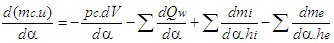
- The calculation of the high pressure cycle of an internal combustion engine is based on the first law of thermodynamics:
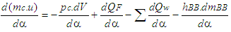 | (1) |
 = change of the internal energy in the cylinder.
  = piston work.
 = fuel heat input.
 = wall heat losses
  = enthalpy flow due to blow-by
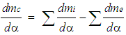
  = blow-by mass flowThe first law of thermodynamics for high pressure cycle states that the change of internal energy in the cylinder is equal to the sum of piston work, fuel heat input, wall heat losses and the enthalpy flow due to blow-by.In order to solve this equation, models for the combustion process and the wall heat transfer, as well as the gas properties as a function of pressure, temperature, and gas composition are required.Together with the gas equation
 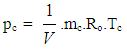 | (2) |
2.2. Combustion Model
- Air Requirement and Heating Value modeling is given below.
2.3. Stoichiometric Air-Fuel Mixture
- The following equation for the stoichiometric air requirement specifies how much air is required for a complete combustion of 1 kg fuel:
 | (3) |
2.4. Lean Mixture
- For lean combustion, the total heat supplied during the cycle can be calculated from the amount of fuel in the cylinder and the lower heating value of the fuel.
2.5. Rich Mixture
- In rich air fuel mixture combustion, the total heat supplied during the cycle is limited by the amount of air in the cylinder. The fuel is totally converted to combustion products even if the amount of air available is less than the amount of stoichiometric air.
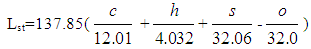
2.6. Heating Value
- The lower heating value is a fuel property and can be calculated from the following formula:
 | (4) |
2.7. Heat Release Approach
- Vibe Two ZoneThe rate of heat release and mass fraction burned is specified by the Vibe function given by equation No.5 below.The first law of thermodynamics is applied separately to the burned and unburned mixture while assuming that the temperatures of these two mixtures is different.
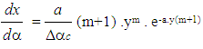 | (5) |
 | (6) |
 | (7) |
 | (8) |
2.8. Gas Exchange Process
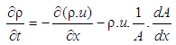
- Basic EquationThe equation for the simulation of the gas exchange process is also the first law of thermodynamics:
 | (9) |
 | (10) |
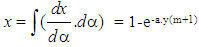
2.9. Piston Motion
- Piston motion applies to both the high pressure cycle and the gas exchange process.For a standard crank train the piston motion as a function of the crank angle α can be written as:
 | (11) |
 | (12) |
2.10. Heat Transfer
- The heat transfer to the walls of the combustion chamber, i.e. the cylinder head, the piston, and the cylinder liner, is calculated from:
 | (13) |
 | (14) |
 | (15) |
2.11. Woschni Model
- The woschni model published in 1978 for the high pressure cycle is summarized as follows:
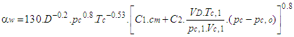 | (16) |
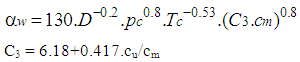 | (17) |
2.12. Fuel Injector
- The fuel injector model is based on the calculation algorithm of the flow restriction. This means that the air flow rate in the fuel injector depends on the pressure difference across the injector and is calculated using the specified flow coefficients. For the injector model, a measuring point must be specified at the location of the air flow meter. In this case the mean air flow at the air flow meter location during the last complete cycle is used to determine the amount of fuel. As is the case for continuous fuel injection, the fuelling rate is constant over crank angle.
2.13. Pipe Flow
- The one dimensional gas dynamics in a pipe are described by the continuity equation
 | (18) |
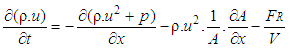 | (19) |
 | (20) |
 :
: | (21) |
 | (22) |
 | (23) |
3. Methodology
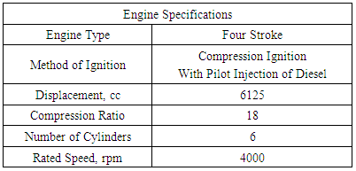
- The methodology used for carrying out computational research investigations with methane 80% and diesel 20% as a dual fuel for automotive engine was as follows:1. The modeling for the existing automotive engine was done in the graphical user interface of the software using the basic elements available in it.2. Suitable models available in the software were chosen for engine heat transfer, combustion, friction power etc.3. The data as per the actual engine was used in the model created in the software.4. Computational mapping for the existing engine was done under maximum load and variable speed operation.5. The characteristic curves for the emissions and performance of the engine were generated as a graphical reference for comparison.6. Next the model was modified for possible use of methane 80% and diesel 20% as a fuel for the same engine. 7. The dual fuel based modeling was done with a view to supply methane as a close replacement for CNG along with air and to inject diesel directly into the engine cylinder towards the end of compression process.8. Simulations were done to generate results for the emissions and performance characteristics of the modified engine in dual fuel mode operation.9. Finally a comparison of the graphical results of the engine with neat diesel and methane 80% and diesel 20% dual fuel modes was done.
4. Results and Discussions
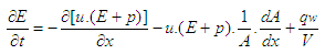
4.1. Effect of Speed on the GHG (CO2) Emissions Produced by the Engine in Diesel and Methane 80% and Diesel 20% Dual Fuel Modes
- The Fig.1 Below shows the effect of speed on the GHG emissions produced by the engine with neat diesel and with 80% Methane and 20% diesel dual fuel modes. It is seen that the GHG emissions increase by increasing the speed with both the fuel modes. This is because the number of power cycles increase with the increase in speed. This further increases the fuel consumption rate which in turn increases the mass flow rate of GHG with higher speeds. Also it is clear that the GHG emissions are much lower with 80% methane and 20% diesel mode as compared to neat diesel mode. This is because each molecule of cetane representing diesel has 16 carbon atoms as compared to methane replacing the conventional CNG which has only one carbon atom in its molecular structures.
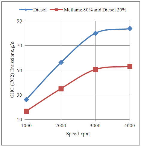 | Figure 1. Effect of Speed on the GHG (CO2) Emissions Produced by the Engine |
4.2. Effect of Speed on the Mass Fraction of GHG (CO2) Emissions in the Exhaust Gas of the Engine in Diesel and Methane 80% and Diesel 20% Dual Fuel Modes
- The fig.2 Below shows the effect of speed on the mass fraction of GHG emissions in the exhaust gas of the engine with diesel and methane 80% and diesel 20% modes. It is seen that the mass fraction of GHG emissions in the exhaust gas of the engine remains fairly constant with change in speed under both modes of fuel. Further the GHG emissions are reduced by about 6% with methane 80% and diesel 20% mode as compared to neat diesel mode. This is because the molecular structure of methane has only one carbon atom as compared to cetane representing diesel having as many as 16 carbon atoms in its molecular structure.
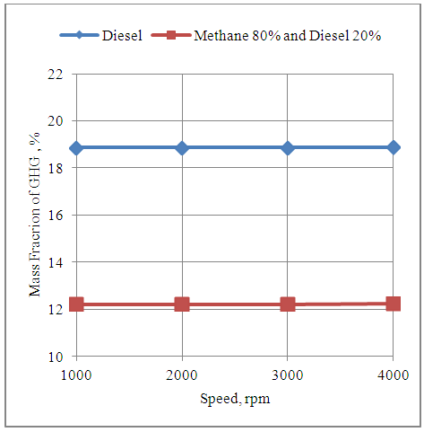 | Figure 2. Effect of Speed on the Mass Fraction of GHG (CO2) Emissions in the Exhaust Gas of Engine |
4.3. Effect of Speed on the CO Emissions Produced by the Engine in Diesel and Methane 80% and Diesel 20% Dual Fuel Modes
- The fig.3 below shows the effect of speed on the CO emissions produced by the engine in neat diesel and methane 80% and diesel 20% modes. It is clear that the CO emissions increase with the increase in the speed of the engine with both the fuel modes. This is because of higher number of power cycles executed by the engine at higher speeds. Further the CO emissions are higher with neat diesel mode as compared to the methane 80% and diesel 20% dual fuel mode. This is because of 16 carbon atoms in the molecular structure of cetane representing diesel as compare to 1 carbon atom in the molecular structure of methane representing CNG which dominates the difference.
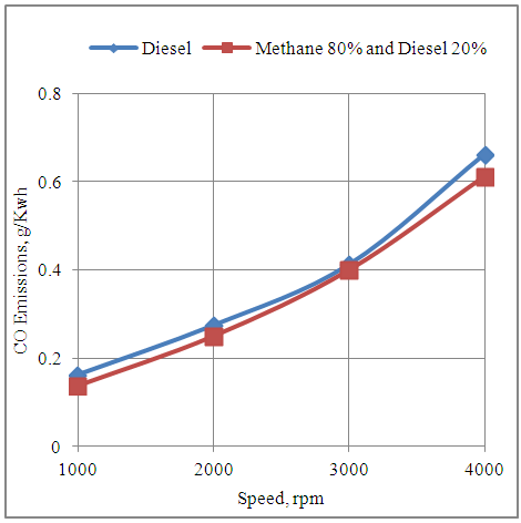 | Figure 3. Effect of Speed on the CO Emissions Produced by the Engine |
4.4. Effect of Speed on the Soot Emissions Developed by the Engine In Diesel and Methane 80% and Diesel 20% Dual Fuel Modes
- The fig.4 below shows the effect of speed on the soot emissions produced by the engine with neat diesel fuel and methane 80% and diesel 20% dual fuel modes. It is seen that the soot emissions are increased by increasing the speed with the dual fuel mode. The soot emissions per unit of energy output increase by increasing the speed of the engine because the time available for combustion decreases under constant duration of combustion period and start of combustion timing. Again under neat diesel mode the soot emissions per unit of energy output first decrease with increase in speed up to 3000rpm and then again increase by increasing the speed further. This is because the speed of 3000rpm represents the speed for maximum power generation as shown by the graphs which follows. The time available for heterogeneous combustion beyond the speed of 3000rpm decreases which results in increase of soot emissions.
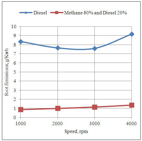 | Figure 4. Effect of Speed on the Soot Emissions Produced by the Engine |
4.5. Effect of Speed on the NOx Emissions Produced by the Engine In Diesel and Methane 80% and Diesel 20% Dual Fuel Modes
- The fig.5 below shows the effect of speed on the NOx emissions produced by the engine with neat diesel and methane 80% and diesel 20% dual fuel modes. It is clear from the graph that the NOx emissions increase with the increase in speed with both the fuel supply systems. This is due to increase in the temperature of the working fluid inside the engine cylinder at higher engine speeds. Further it is seen that the NOx emissions are almost same with both types of fuel modes. This shows that the thermodynamic conditions as well as the concentration of oxygen and nitrogen of air in the engine cylinder are such that finally the NOx emissions of the engine match under two modes.
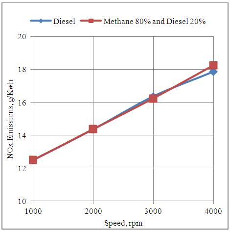 | Figure 5. Effect of Speed on the NOx Emissions Produced by the Engine |
4.6. Effect of Speed on the Power Developed by the Engine in Diesel and Methane 80% and Diesel 20% Dual Fuel Modes
- The fig.6 below shows the effect of speed on the power developed by the engine with neat diesel and methane 80% and diesel 20% dual fuel modes. It is seen that the power of the engine increases by increasing the speed up to 3000rpm. The reason is that the engine executes more number of power cycles per unit time at higher speeds. Further increase in the engine speed shows drop in power with both fuel modes. This is because the heterogeneous combustion with neat diesel and the combustion with pilot injection of diesel in homogeneous methane-air mixture experiences drop in time available for combustion which results in the drop in power. Also the engine develops higher power in neat diesel mode as compared to methane 80% and diesel 20% dual fuel mode. This is because of drop in volumetric efficiency with the 80% methane component of the dual fuel.
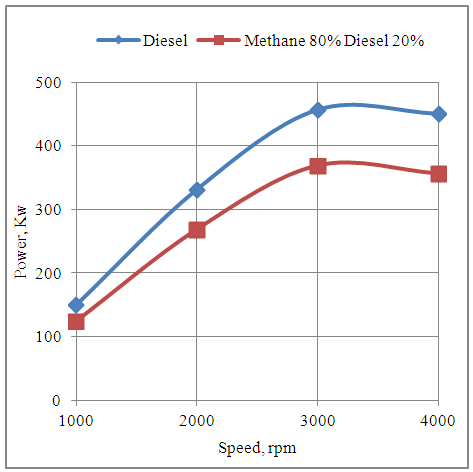 | Figure 6. Effect of Speed on the Power Developed by the Engine |
4.7. Effect of Speed on the Torque Developed by the Engine in Diesel and Methane 80% and Diesel 20% Dual Fuel Modes
- The fig.7 below shows the effect of speed on the torque developed by the engine with neat diesel and methane 80% and diesel 20% dual fuel modes. It is clear that the torque increases up to the maximum brake torque timing based speed of 2000rpm. Further increase in speed shows the drop in toque developed by the engine with both the fuel modes. Also the engine develops higher torque with neat diesel fuel as compared to the dual fuel mode of methane 80% and diesel 20%. This is because of lower volumetric efficiency in dual fuel mode operation.
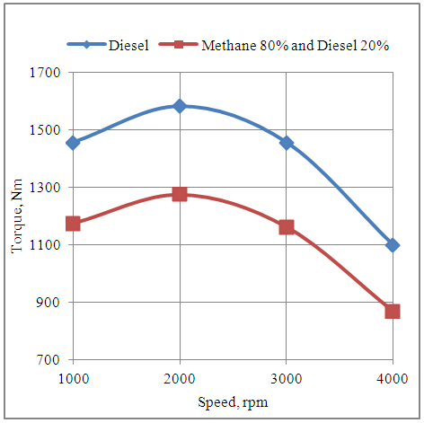 | Figure 7. Effect of Speed on the Torque Developed by the Engine |
4.8. Effect of Speed on the Brake Specific Fuel Consumption of the Engine in Diesel and Methane 80% and Diesel 20% Dual Fuel Modes
- The fig.8 below shows the effect of speed on the fuel consumption per unit of energy output with neat diesel and methane 80% and diesel 20% dual fuel modes. It is clear that the fuel consumption per unit of energy output is minimum at the maximum brake torque timing of 2000rpm. The engine consumes more fuel per unit of energy output on the either side of this speed. Further it is seen that the fuel consumption per unit of energy output with neat diesel is higher than that with methane 80% and diesel 20% dual fuel mode. This is because the lower fuel consumption rate in the dual fuel mode dominates and decreases the value of BSFC in this mode.
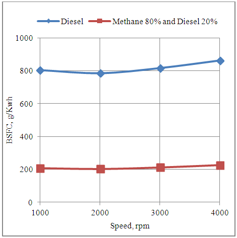 | Figure 8. Effect of Speed on the Brake Specific Fuel Consumption of the Engine |
4.9. Effect of Speed on the Exhaust Gas Temperature of the Engine in Diesel and Methane 80% and Diesel 20% Dual Fuel Modes
- The fig.9 below shows the effect of speed on the temperature of the exhaust gas produced by the engine with neat diesel and methane 80% and diesel 20% dual fuel modes. It is clear from the graph that the temperature increases with the increase in speed with both the fuel modes because of more number of power cycles executed per unit time at higher speeds. Further the temperature of the exhaust gas is higher with neat diesel as compared to methane 80% and diesel 20% dual fuel modes. The drop in temperature with dual fuel mode is due to drop in volumetric efficiency in this mode of fuel supply.
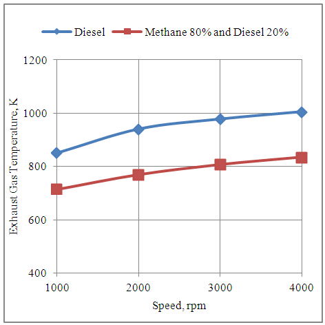 | Figure 9. Effect of Speed on the Exhaust Gas Temperature of the Engine |
5 Conclusions
- 1. The results showed that there is a potential to reduce the GHG (CO2) emissions by about 35.8% at 1000rpm to about 36.57% at 4000rpm. in the methane 80% and diesel 20% dual fuel mode operation as compared to the neat diesel operation. 2. The mass fraction of the GHG emissions in the exhaust gas can be reduced by about 6.66% in the methane 80% and diesel 20% dual fuel mode as compared to the neat diesel fuel mode. 3. The CO emissions produced by the engine were reduced by 15.94% at 1000rpm to 7.54% at 4000rpm in the methane 80% and diesel 20% dual fuel mode operation as compared to neat diesel operation. 4. Further the soot emissions produced by the engine in methane 80% and diesel 20% dual fuel mode operation were reduced by 89.52% at 1000rpm to 85.13% at 4000rpm as compared to neat diesel operation. 5. There was no appreciable change in the NOx emissions produced by the engine when its mode of operation was shifted from the neat diesel to the methane 80% and diesel 20% dual fuel mode. 6. The engine performance in neat diesel and methane 80% and diesel 20% dual fuel modes was satisfactory. However the engine developed lower power and torque in methane 80% and diesel 20% dual fuel mode as compared to neat diesel mode. 7. The fuel consumption per unit energy output was lower by about 74.09% at 1000rpm to about 73.69% at 4000rpm in methane 80% and diesel 20% dual fuel mode as compared to neat diesel mode. 8. Modifying the existing neat diesel compression ignition engines into the methane 80% and diesel 20% dual fuel engines will help in reducing the GHG emissions and therefore help in reducing the fear of global warming and its consequences due to the ever increasing CO2 emissions from carbon based fuels.
ACKNOWLEDGEMENTS
- Author is thankful to AVL Austria and AVL India Ltd Gurgaon for providing license for the AVL BOOST thermodynamic engine simulation software for academic research purposes.
Appendix-A
- Nomenclaturea = speed of sound, m/secA = pipe cross-section, m2Aeff = effective flow area, m2Ai = surface area (cylinder head, piston, liner), m2AFCP = air fuel ratio of combustion productsAgeo = geometrical flow area, m2c = mass fraction of carbon in the fuelcV = specific heat at constant volume, J/Kg.Kcp = specific heat at constant pressure, J/Kg.KCm = mean piston speed, m/secCu = circumferential velocity, m/seccu = circumferential velocity, m/secD = cylinder bore, mdmi = mass element flowing into the cylinder, kgdme = mass element flowing out of the cylinder, kgdvi = inner valve seat diameter (reference diameter), m
 = blow-by mass flow, kg/degree of crank anglee = piston pin offset, mE = energy content of the gas
 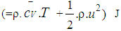 f = fraction of evaporation heat from the cylinder chargeFR = wall friction force, Nh = mass fraction of hydrogen in the fuelhBB = enthalpy of blow-by, J/Kghi = enthalpy of in-flowing mass, J/Kghe = enthalpy of the mass leaving the cylinderHu = lower heating value, J/Kgk = ratio of specific heatsl = con-rod length, mm = shape factor
 = mass flow rate, kg/secmc = mass in the cylinder, kgmev = evaporating fuel, kgmpl = mass in the plenum, kgn = mass fraction of nitrogen in the fuelo = mass fraction of oxygen in the fuelp = static pressure, barP01 = upstream stagnation pressure, barPc,o = cylinder pressure of the motored engine, barPc,1 = pressure in the cylinder at IVC, barppl = pressure in the plenum, barpc = cylinder pressure, barp2 = downstream static pressure, barqev = evaporation heat of the fuel, J/kgqw = wall heat flow, JQ = total fuel heat input, JQF = fuel energy, JQwi= wall heat flow (cylinder head, piston, liner), Jr = crank radius, mR0 = gas constant, J/mol.Ks = piston distance from TDC, mt = time, secT = temperature, KTc,1 = temperature in the cylinder at intake valve closing (IVC), KTc = gas temperature in the cylinder, KTwi = wall temperature (cylinder head, piston, liner), KTL = liner temperature, KTL,TDC = liner temperature at TDC position, KTL,BDC = liner temperature at BDC position, KTw = pipe wall temperature, KT01= upstream stagnation temperature, Ku = specific internal energy, J/Kgu = flow velocity, m/secV = cylinder volume, m3V = cell volume (A.dx), m3VD = displacement per cylinder, m3w = mass fraction of water in the fuelx = relative stroke (actual piston position related to full stroke)α = crank angle, degreesαo = start of combustion, crank angle degreesΔαc = combustion duration, crank angle degreesαw = heat transfer coefficient, J/m2.Kρ = density, kg/m3μσ = flow coefficient of the portψ = crank angle between vertical crank position and piston TDC position, degrees
  = wall friction coefficientΔt = time step, secΔx= cell length, m
Appendix-B
Appendix-C