Nabil J. Yasin, Mahmood H. Oudah
Engineering Technical College-Baghdad, Middle Technical University, Baghdad, Iraq
Correspondence to: Mahmood H. Oudah, Engineering Technical College-Baghdad, Middle Technical University, Baghdad, Iraq.
| Email: |  |
Copyright © 2018 Scientific & Academic Publishing. All Rights Reserved.
This work is licensed under the Creative Commons Attribution International License (CC BY).
http://creativecommons.org/licenses/by/4.0/

Abstract
The heat transfer and flowing resistance characteristics of air flow crossing over pin finned tube heat exchanger was studied numerically and experimentally. The purpose of this study is to improve the heat transfer characteristics of a pin finned-tube for better performance. A plain and solid pin finned tube heat exchanger models were fabricated and used to examine the heat transfer coefficient enhancement. In the numerical study, the finite volume mesh generation was performed using ANSYS Design modular and Fluent 18.0. Plain, solid and perforated pin finned tubes were studied numerically. The experimental results showed that Nusselt number is approximately 27% higher than that of the plain tube, while, the pressure drop value is 17% higher than that of the plain tube. The numerical results showed that perforated finned tube provides a good reduction in surface temperatures. The use of perforated pin finned tube results in increasing Nusselt number by 26% and increasing pressure drop by 22% in comparison with solid pin finned tube. A comparison between the numerical and experimental results showed a good agreement between them. Finally, correlation equations were developed for the heat transfer and friction factor.
Keywords:
Pin Finned Tube, Perforated Fin, Heat Exchanger, Heat Transfer Performance
Cite this paper: Nabil J. Yasin, Mahmood H. Oudah, The Effect of Solid and Perforated Pin Fin on the Heat Transfer Performance of Finned Tube Heat Exchanger, International Journal of Energy Engineering, Vol. 8 No. 1, 2018, pp. 1-11. doi: 10.5923/j.ijee.20180801.01.
1. Introduction
Finned tubes are usually used in heat exchangers to increase heat transfer between hot and cold fluids. Different types of fins are used in finned tube heat exchanger ranging from relatively simple shapes such as annular, rectangular, longitudinal, square or pin fins to a combination of different geometries. Pin fins are one of the very effective methods to enhance heat exchanger performance. A pin fin is a cylindrical or other shaped element attached perpendicular to a tube wall in the finned tube. There have been many investigations studying the heat transfer and pressure drop of the micro pin fin heat sink and various fin geometries of finned tube heat exchangers. K. Azar and C. D. Mandrone, (1994) [1] studied experimentally the effect of pin fin density on thermal resistance of unshrouded pin fin heat sink. Six heat sinks with different numbers of round pin fins were constructed. The results showed that thermal resistance was a function of air velocity and its value did not decrease with the increase of a number of pin fins. G. Tanda, (2001) [2] studied experimentally heat transfer and pressure drop of rectangular channel equipped with diamond cross-sectional pin fins array. Both staggered and in-line arrangement were used for different values of longitudinal and transverse spacing. Local variations in heat transfer coefficients induced by arrangements of the diamond-shaped elements were measured and discussed. The results show that the distribution of heat transfer coefficient is strongly influenced by the geometrical array arrangement of the fins. Finally, as compared with the unfinned surface, finned surface with staggered arrangement had highest heat transfer enhancement. A. Kosar and Y. Peles, (2007) [3] investigated experimentally the heat transfer and pressure drop associated with the forced flow of deionized water over five micro pin fin heat sinks with different spacing, arrangements, and shapes. Nusselt numbers and friction factors were obtained over Reynolds numbers ranging from 14 to 720. The thermal and hydraulic characteristics were measured to evaluate and compare the heatsinks performances. The results indicate that large spacing between pin fins and inline configurations results in lower heat transfer coefficients compared to densely populated and staggered arrangements. Y. T. Yang and H. S. Peng, (2008) [4] performed a numerical simulation of the heat sink with a non-uniform fin height with a confined impingement cooling to evaluate the possibility of improving the heat sink performance by minimizing the junction temperature of the heat sink without sacrificing the whole thermal performance. The governing equations were discretised using a control volume based finite difference method with a power-law scheme on an orthogonal non-uniform staggered grid. The well-known k-ε two-equation turbulence model was employed to describe the turbulent structure and behaviour. The results showed that an adequate non-uniform fin height design could decrease the junction temperature and increase the enhancement of the thermal performance simultaneously. I. Kotcioglu, et. al (2011) [5] studied experimentally convective heat transfer and pressure drop in cross-flow heat exchanger of hexagonal, square and circular pin fin arrays. The pin–fins were arranged in an in-line manner and inserted periodically into the rectangular channel in various pin geometries. The results show that the circular pin fin has smaller pressure drop than the others, but the hexagonal pin fin has higher heat transfer characteristics in an in-line arrangement. Moreover, some Empirical equations are derived to correlate the mean Nusselt number and friction coefficient as a function of the Reynolds number, pin-fin frontal surface area and the total surface area. Y. Rao et. al (2011) [6] performed an experimental and numerical investigation to determine heat transfer and friction factor performance in rectangular channels with staggered arrays of pin fin-dimple hybrid structures and pin fins in the Reynolds number range of 8200–54,000. The friction factor, Nusselt number and the overall thermal performance parameters of the pin fin-dimple and the pin fin channels were determined and compared with the previously published experimental data of a smooth rectangular channel. In addition, three-dimensional numerical computations were carried out to investigate the physical details of the flow and heat transfer in the pin fin and pin fin-dimple channels. The experimental results showed that the pin fin-dimple channel has improved the convective heat transfer performance in comparison with the pin fin channel. The computations and experimental results, both had similar trends, however, the heat transfer enhancement and the flow friction reduction capability in the pin fin-dimple channel. H. Shafeie et. al (2013) [7] investigated numerically laminar forced convection in heat sinks with micro pin-fin structure. A water-cooled pin-finned microchannel heat sinks and pin fin heat sinks were investigated using either oblique or staggered pin fins arrangements. The Navier-Stokes and energy equations for the liquid region and the energy equation for the solid region are solved simultaneously to determine the hydraulic and heat transfer performance of the heat sinks. The results showed that for the same pumping power, the heat removal of the finned heat sinks is lower than that of the optimum simple microchannel heat sinks and the oblique orientation of short pins had the highest heat removal for a given pumping power. Furthermore, the finned heat sinks perform slightly better than the optimum simple microchannel heat sink for small pumping power.
2. Experimental Setup
The schematic diagram (Fig. 1) shows the experimental test rig which consists mainly of wind tunnel, water storage tank, axial fan, water pump, measurement devices and the heat exchanger.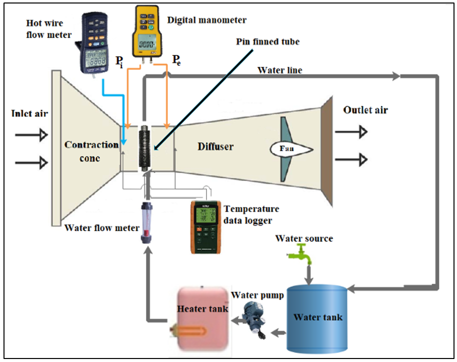 | Figure 1. Schematic diagram of the experimental set-up |
2.1. Test Preparations
Prior to conducting the experimental tests, the test rig is subjected to a thorough check which includes the following:Ÿ Checking the water delivery by heating the water to a specific temperature and checking the time required to reach the specified temperature. This time represents the starting time of experiments.Ÿ Checking that the experimental rig is located in a space far from environmental effects such as direct sunlight, vibrations, wind, and temperature fluctuations which might affect test results. Ÿ Finally, a leakage test was carried out by filling the heat exchanger and other water line linkage with water at (76°C) to ensure that no leakage occurs during the experiments.
2.2. Experimental Procedure
Two samples of the plain tube and solid pin finned tube heat exchangers as shown in (Fig. 2) were fabricated and tested. For each sample, seven different airspeeds were used for testing. Generally, (14) experimental runs were conducted.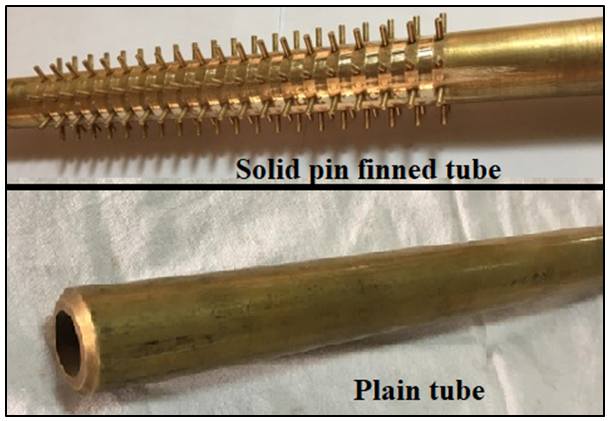 | Figure 2. Heat exchangers used in experimental work |
The test procedure involves the following:1. The room temperature (Troom) is set at 25°C.2. The water heater is switched on and the water temperature inside the heater tank at 76°C.3. The digital differential manometer, hot wire flow meter and temperature data logger are switched on.4. The axial fan is switched on to inhale air inside the duct through the test section and the inverter selector is adjusted to maintain the required airspeed within the test section.5. The water pump is switched on to pump the water through the heat exchanger.6. Readings of air velocity, water flow rate and temperature were recorded every (5 minutes) to ensure their stability.7. The time required to reach steady state is recorded. This time represents the starting time of experiments.
2.3. Error Analysis
The experimental uncertainties have been determined by a standard error analysis. According to the measurement instruments, the maximum measurement errors of the flow rate are ±3%, the length, as well as the pressure drop, are ±2.0% and ±2.8% respectively; and the air properties (density and viscosity) are ±1.3%. According to the standard error analysis method suggested by Kline and McClintock [8], the measurement errors of Re, f and Nu are ±3.8%, ±6.6% and ±4.2% respectively.
3. CFD Modeling and Simulation
Three-dimensional simulation of airflow and heat transfer over pin finned tube of solid and perforated fins was employed. The well-known ANSYS-FLUENT version 18.0 was used for CFD modelling, simulation and post-processing.
3.1. Geometry
A three-dimensional pin finned tube was simulated using ANSYS-Design Modeller software. Because of the limitation of computer speed (CPU) to simulate the whole geometry, the numerical study was performed by taking a section representing (1/10) of origin tube length. This section consists of 33 (mm) of the tube. Three cases were studied numerically for the plain tube, solid pin finned tube and perforated pin finned tube as shown in (Fig. 3). The governing dimensional equations of energy, continuity and Naiver-Stocks equation were used by FLUENT to solve turbulent flow field.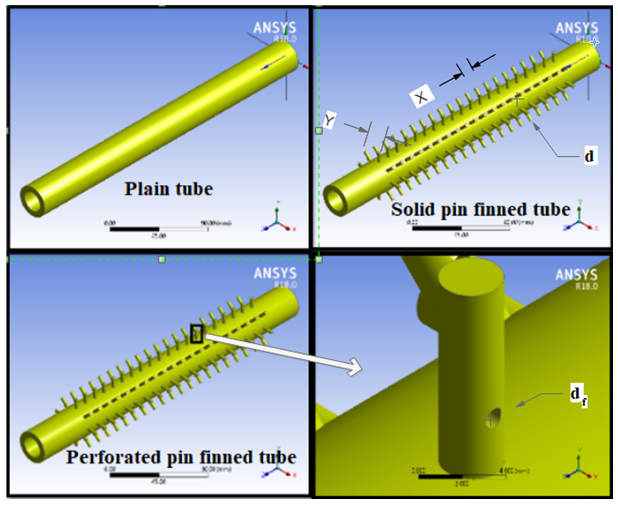 | Figure (3). Heat exchangers used in numerical work |
3.2. Boundary Conditions
When the governing differential equations are set up to describe the problem in the domain, it is important to adjust the boundary conditions which specify the values of the velocity and temperature to obtain similar conditions that considered in the experimental work.In the ANSYS-FLUENT software, boundary conditions must be specified at each surface defined in the mesh generation process. Specifically, the velocity and temperature must be specified at each surface as shown in (Fig. 4).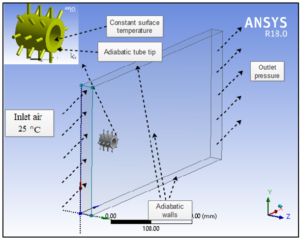 | Figure 4. Boundary conditions |
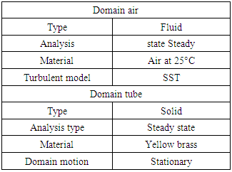
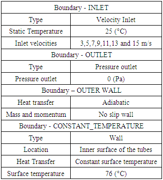
The Domain Physics and Boundary Physics are listed in tables (1), (2) and (3). The other boundary condition is a non-slip condition on all surface (u=v=0). A tetrahedral mesh of finite volume method used and the number of elements was 2135254. The numerical convergence of the whole solution was carried out. Table (1). Domain physics
 |
| |
|
Table (2). Boundary Conditions of the case under study
 |
| |
|
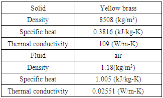
Table (3). Material Properties
 |
| |
|
(Fig. 3) shows the plain tube, solid pin finned tube and perforated pin finned tube with inner diameter (Di=20 mm), outer diameter (Do= 32 mm), tube length (L=330 mm), fin height (b=10 mm), fin diameter (d=3 mm), longitudinal fin spacing (x=12 mm), angle between fins (y=45°), perforated diameter (df=1 mm) and perforation position (r= 3 mm from fin base).
4. Data Analysis
The first law of thermodynamics requires that the rate of heat transfer from the hot fluid is equal to the rate of heat transfer to the cold one [9]. Where | (1) |
The rate of heat transfer to or from an isothermal surface can be determined from | (2) |
Then the heat transfer rate can be determined from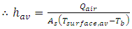 | (3) |
 | (4) |
The Nusselt number and Reynolds number are calculated as follows: | (5) |
 | (6) |
The friction factor (f) can be calculated by measuring the pressure upstream and downstream of the tested tube and according to the equation [10]: | (7) |
 | (8) |
The total thermal resistance Rth. is considered as follows: | (9) |
Overall enhancement ratio is defined as the ratio of heat transfer enhancement ratio to the friction factor ratio based on the equal pumping power [11]. | (10) |
5. Results & Discussion
The experimental data were compared with the result obtained by the well-known correlation under a similar condition to evaluate the validity of the plain tube. Comparison of Nusselt number is shown in (Fig. 5). As shown, the experimental results of heat transfer are in good agreement with empirical correlations developed by Churchill–Bernstein equation [9]. It is noticed that the average deviation in Nusselt number is approximately 6%, and the maximum deviation 20% with Churchill correlation.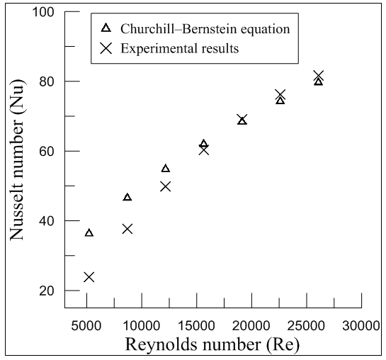 | Figure (5). Comparison of Nusselt number for experimental results of the plain tube with published empirical Churchill–Bernstein equation |
5.1. Experimental Results
A comparison between the plain tube and the finned tube was carried out to show the improvement in heat transfer as a result of using the finned tube. (Fig 6) shows the values of Nusselt number for plain tube and solid finned tube. A significant improvement in Nusselt number is obtained when pin finned tube is used due to the increase of the heat dissipation area.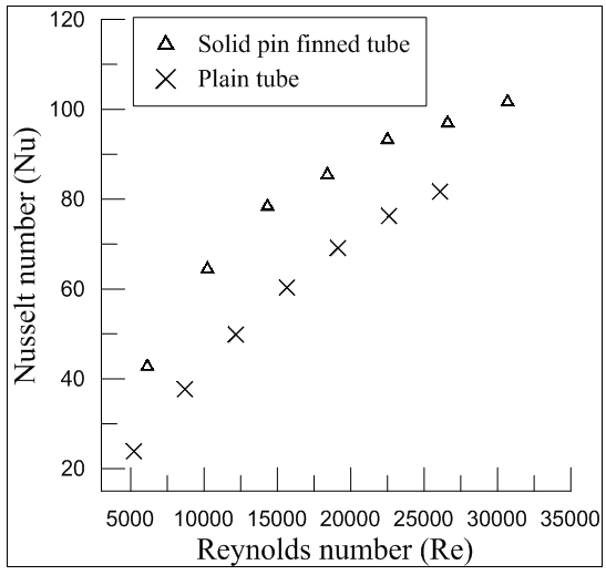 | Figure (6). Comparison of (Nu vs Re) between the plain tube and the solid pin finned tube |
The friction factor for solid finned tube increased as compared with the plain tube as shown in (Fig. 7). This is attributed to the presence of strong swirl flow, moreover, fins increase pressure drag at the tangential contact between secondary flow and the wall surface of the tube, these two factors led to the increase of the friction drag.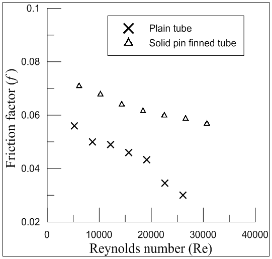 | Figure (7). Comparison of (f vs Re) between the plain tube and the solid pin finned tube |
The ratio of Nusselt number for the finned tube to the Nusselt number for the plain tube (Nu/Nus) was evaluated as shown in (Fig. 8). It is clearly evident that the solid pin finned tube performance being significantly effective at lower Reynolds number.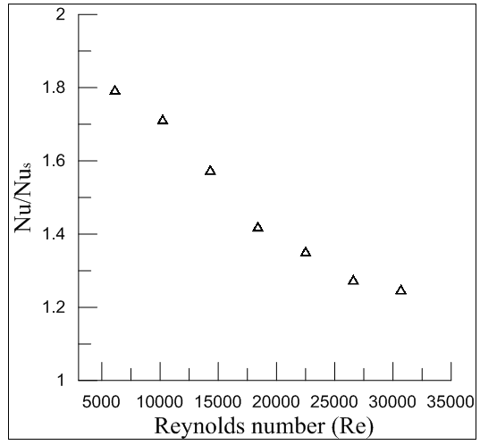 | Figure (8). Variation of Nu/Nus based on projected area with Reynolds number |
Thermal Resistance (Rth) is defined as the ratio of the difference between temperatures of fin base and environment to heat transfer by convection and it was calculated using (Eq. 9). (Fig. 9) shows the variation of total thermal resistance with Reynolds number. It is clearly evident that the thermal resistance of plain tube is greater than pin finned tube because less heat dissipated from plain tube heat exchanger as compared to finned tube heat exchanger. 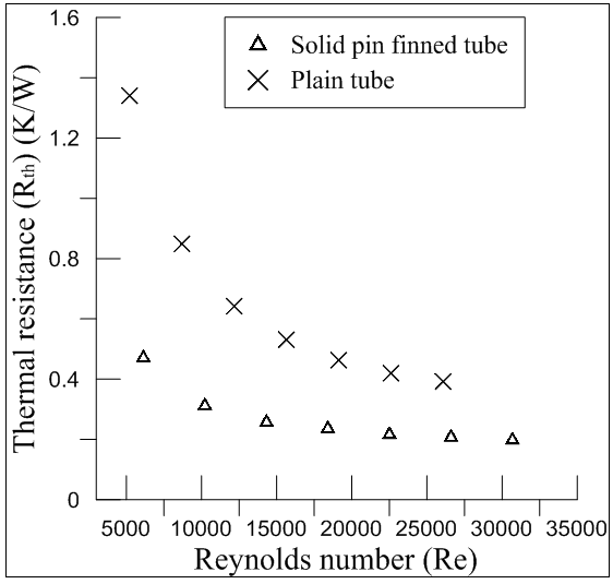 | Figure (9). Effect of solid fins on thermal resistance |
(Eq. 10) expresses the heat transfer and pressure drop of the plain tube, and according to the relationship, the overall enhancement ratio should be greater than unity. The greater value indicates better performance for that geometry, while a value less than one indicates bad or worthless approach [11]. (Fig. 10) shows the overall enhancement ratio for solid pin finned tube heat exchanger. The result shows the overall enhancement efficiency decreases with the increase in Reynolds number. The results also indicate that at lower Reynolds number the overall enhancement ratio is better. The higher value of overall enhancement ratio indicates more effective heat transfer than friction factor.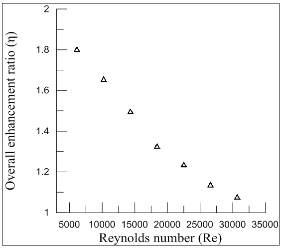 | Figure (10). Variation of overall enhancement ratio with Reynolds number |
5.2. Numerical Results
Under the operating conditions and physical properties mentioned earlier, 3D steady state dynamic simulation for a pin-finned tube heat exchanger was performed. In this work, the estimation of heat dissipation was carried out with the yellow brass material of tube and pin fins. The simulations were performed by using ANSYS Fluent 18.0 for the samples. As shown from velocity vector contour (Fig. 11) the flow seems to be high turbulent near fins due to fin shape which creates wakes in backflow. Generally, in the solid finned tube, it can be noticed that there is a separation of flow from the tube which occurred at an angle of approximately 130° from the stagnation point, resulting in a recirculation zone in the downstream region. Perforated fin improves mixing due to enhanced turbulence and as a result, increases the separation angle. This increase in air mixing is due to destruction or reduction in the thickness of viscous boundary layer and this leads to increasing the turbulence and as a result, increasing the heat transfer coefficient.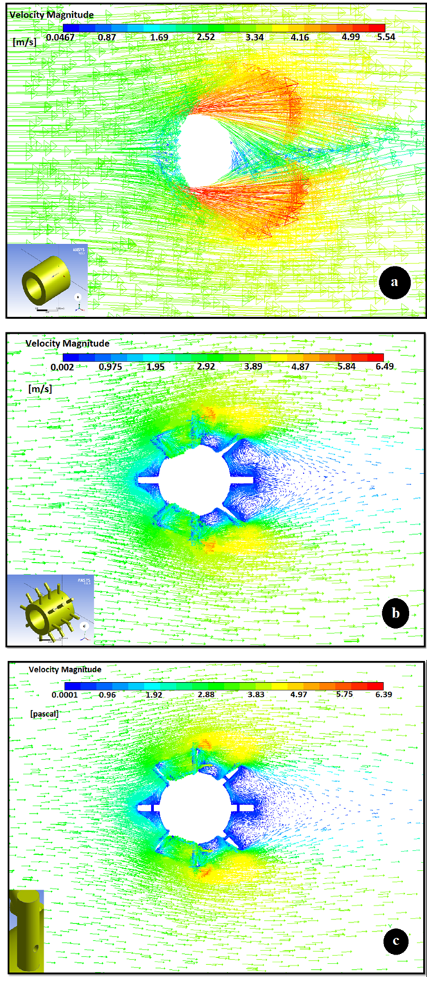 | Figure (11). 2-D Velocity vector projection of 3-D simulation at 3 (m/s) (a) Plain tube, (b) solid pin finned tube and (c) perforated pin finned tube |
(Fig. 12) shows the effect of perforation on a Nusselt number based on the numerical results. It is clear that perforated fin gives good enhancement in the Nusselt number where the enhancement of heat transfer due to perforation is 1.42. (Fig. 13) shows the temperature contour of the plain tube, solid finned tube and perforated finned tube.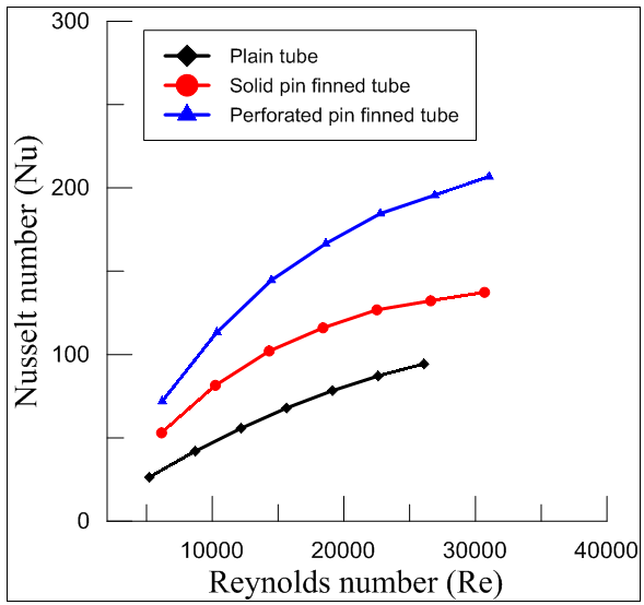 | Figure (12). The effect of the solid fin and perforated fin on a Nusselt number based on numerical results |
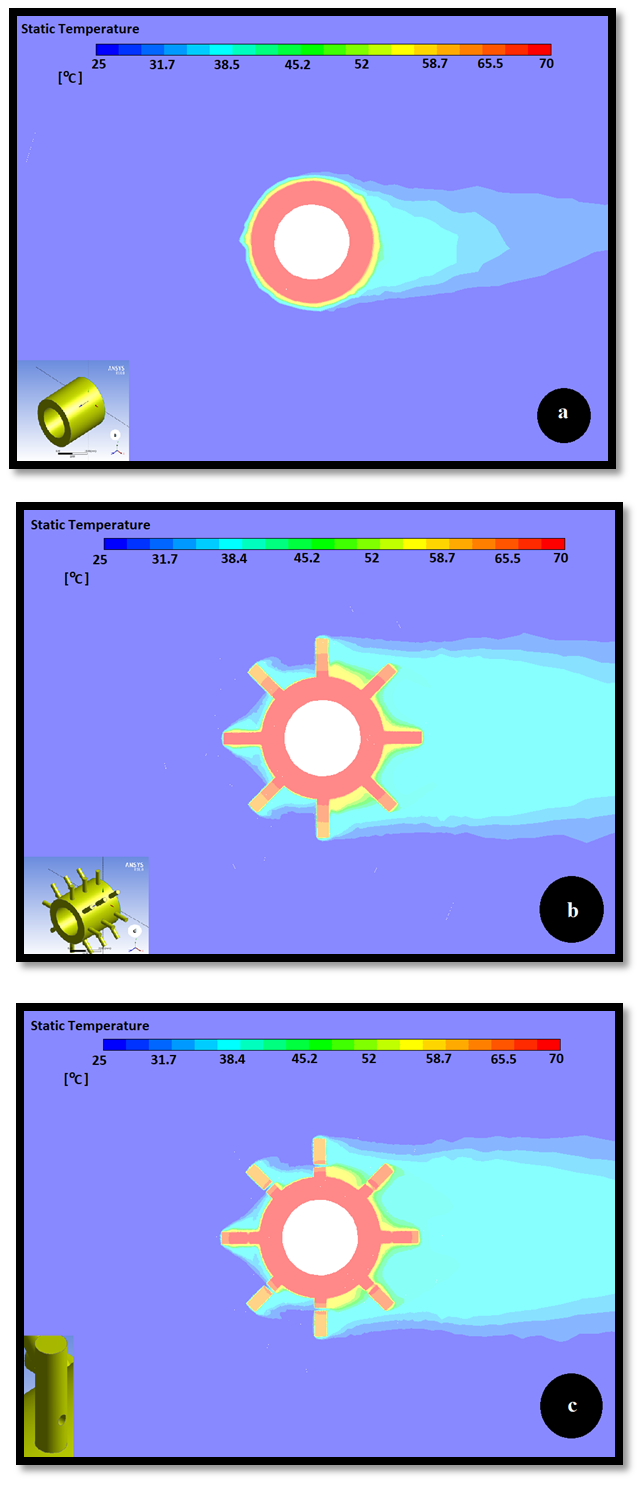 | Figure (13). 2-D Temperature contour projection of 3-D simulation at 3 (m/s) (a) Plain tube, (b) solid pin finned tube and (c) perforated pin finned tube |
(Fig. 14) shows the values of friction factor for the plain tube, solid finned tube and perforated finned tube according to the numerical results. It is clearly evident that the friction factor of the perforated fin is higher than that of the solid fin. The greater friction factor refers to an increase in pressure drop in case of perforated one, which is due to excessive flow disturbances produced by perforations. The increase of pressure drop with perforation sample increased by 1.45 relative to the solid fin. (Fig. 15) shows the static pressure contour for the plain tube, solid finned tube and perforated finned tube.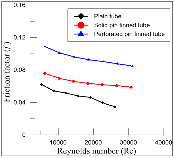 | Figure (14). The effect of the solid fin and perforated fin on friction factor based on numerical results |
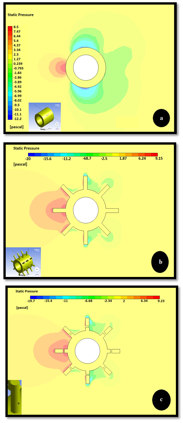 | Figure (15). 2-D Pressure contour projection of 3-D simulation at 3 (m/s) (a) Plain tube, (b) solid pin finned tube and (c) perforated pin finned tube |
The ratio of Nusselt number of the solid finned tube (Nu/Nus) and perforated finned tube to the Nusselt number of the plain tube is shown in (Fig. 16) where perforation leads to a good enhancement of the Nusselt number.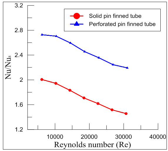 | Figure (16). Variation of Nu/Nus for solid finned tube and perforated finned tube based on the projected area with Reynolds number based on numerical results |
(Fig. 17) shows the variation of total thermal resistance with Reynolds number for solid pin finned tube and perforated pin finned tube. The thermal resistance of the solid fin is higher than that of perforated fins which are attributed the increase in the heat transfer as a result of heat transfer coefficient increase.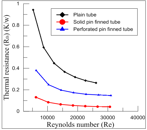 | Figure (17). The effect of solid fins and perforated fins on thermal resistance based on numerical results |
(Fig. 18) shows the overall enhancement ratio of the solid pin finned tube and perforated pin finned tube heat exchanger. The result shows a good improvement in overall enhancement efficiency due to perforation. 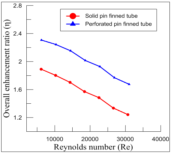 | Figure (18). Variation of overall enhancement ratio with Reynolds number based on numerical results |
6. Present Work Correlations and Validation
6.1. Enhancement of Heat Transfer and Friction Factor Correlations
The average Nusselt number and friction factor of the pin finned tube heat exchanger cases were correlated as a function of Reynolds number, (x/Dh), (y/Dh), (d/Dh), (ΔT) and (∆P) by using STATISTICA 12 program, the correlation coefficient (R2) is equal (0.96) and the following expressions were obtained: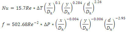 These equations are valid in a range of (5000 ≤ Re ≥ 31000). It must be noted that when these correlations have used the temperature for Nusselt number correlation is in Kelvin and pressure drop is in Pascal for friction factor correlation.
6.2. Validation
(Fig. 19) and (Fig. 20) show the comparison between numerical and experimental results of the Nusselt number and friction factor of plain tube and solid pin finned tube. A good agreement is observed for heat transfer enhancement with a maximum deviation of ±10% between the present experimental and numerical results. In addition, it is clearly evident that when comparing friction factor between present experimental and numerical results there is a good agreement with maximum deviation ± 8%.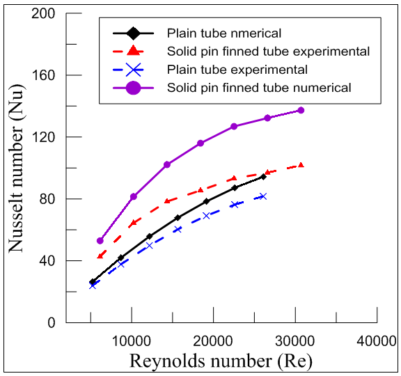 | Figure (19). Nusselt number validation of numerical result with experimental results |
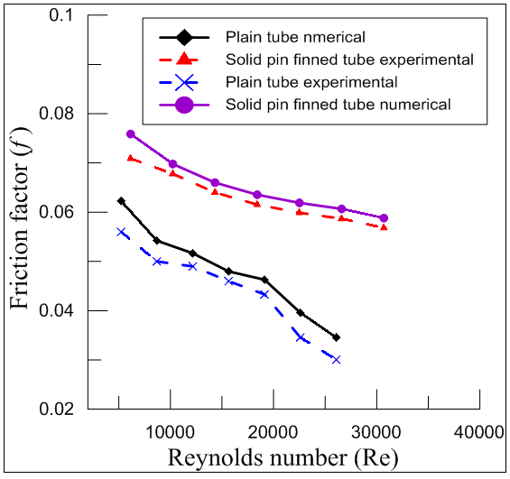 | Figure (20). Friction factor validation of numerical result with experimental results |
7. Conclusions
The present work mainly involves heat transfer characteristics of perforated and solid pin finned tube heat exchanger. Finned tubes are used for the present work in order to improve the heat transfer rate of the heat exchanger. The conclusions are drawn as:1. The average Nusselt number increased the with an increase in Reynolds number. The Nusselt number of the perforated model is approximately 26% higher than that of solid fin model.2. Friction factor increased in pin finned tube model and it also increased with perforation due to increase in the pressure drop. The pressure drop of perforated fin model is approximately 22% higher than that of solid fin model.3. Perforated finned tube heat exchanger provided better heat transfer characteristics than both plain tube and solid finned model.4. A higher difference in surface temperature and air temperature is obtained with perforated fins as compared with solid fins.
8. Recommendations
It is recommended that future research should investigate:1- The effect of internally finned tube beside external finned tube.2- Using Nano-fluid inside tube and water outside the tube.3- The effect of multiple fin`s perforations on heat transfer performance.
Nomenclature
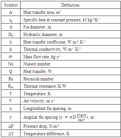 Greek symbols
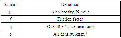 Subscript
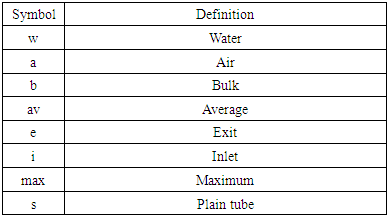
References
| [1] | AZAR, Kaveh; MANDRONE, Carlo D. Effect of pin fin density of the thermal performance of unshrouded pin fin heat sinks. TRANSACTIONS-AMERICAN SOCIETY OF MECHANICAL ENGINEERS JOURNAL OF ELECTRONIC PACKAGING, 1994, 116: 306-306. |
| [2] | TANDA, Giovanni. Heat transfer and pressure drop in a rectangular channel with diamond-shaped elements. International Journal of Heat and Mass Transfer, 2001, 44.18: 3529-3541. |
| [3] | KOSAR, Ali; PELES, Yoav. TCPT-2006-096. R2: micro scale pin fin heat sinks—Parametric performance evaluation study. IEEE Transactions on Components and Packaging Technologies, 2007, 30.4: 855-865. |
| [4] | YANG, Yue-Tzu; PENG, Huan-Sen. Numerical study of pin-fin heat sink with un-uniform fin height design. International Journal of Heat and Mass Transfer, 2008, 51.19: 4788-4796. |
| [5] | KOTCIOGLU, Isak; CALISKAN, Sinan; BASKAYA, Senol. Experimental study on the heat transfer and pressure drop of a cross-flow heat exchanger with different pin–fin arrays. Heat and mass transfer, 2011, 47.9: 1133. |
| [6] | RAO, Yu; XU, Yamin; WAN, Chaoyi. An experimental and numerical study of flow and heat transfer in channels with pin fin-dimple and pin fin arrays. Experimental Thermal and Fluid Science, 2012, 38: 237-247. |
| [7] | SHAFEIE, Haleh, et al. Numerical study of heat transfer performance of single-phase heat sinks with micro pin-fin structures. Applied Thermal Engineering, 2013, 58.1: 68-76. |
| [8] | KLINE, Stephen J. The description of uncertainties in single sample experiments. Mech. Engg., 1953, 75: 3-9. |
| [9] | YUNUS, A. Cengel, et al. Heat transfer: a practical approach. MacGraw Hill, New York, 2003. |
| [10] | CENGEL, Yunus A.; CIMBALA, John M.; KANOĞLU, M. Fluid mechanics, fundamentals and applications, 2006. |
| [11] | HASANPOUR, A.; FARHADI, M.; SEDIGHI, K. A review study on twisted tape inserts on turbulent flow heat exchangers: The overall enhancement ratio criteria. International communications in heat and mass transfer, 2014, 55: 53-62. |

 Abstract
 Reference
 Full-Text PDF
 Full-text HTML