International Journal of Energy Engineering

p-ISSN: 2163-1891    e-ISSN: 2163-1905

2017;  7(4): 91-113

doi:10.5923/j.ijee.20170704.01


Coil-EEFL Lamps as a Promise Candidate for Green Energy Project of UN

Lyuji Ozawa

Professor and Licensed Consultant on Applied Science, Beijing, China

Correspondence to: Lyuji Ozawa, Professor and Licensed Consultant on Applied Science, Beijing, China.

Email:

Copyright © 2017 Scientific & Academic Publishing. All Rights Reserved.

This work is licensed under the Creative Commons Attribution International License (CC BY).
http://creativecommons.org/licenses/by/4.0/

Abstract

We have studied the incandescent lamps for aiming to the contribution of the Paris Agreement of the United Nation. We have found that only FL lamps hold the great potential as the candidate to the UN project. However, the careful study on the commercial HCFL lamps has produced with the hypotheses without the scientific proofs. After the clarification of the hypotheses, we have developed the coil-EEFL lamps that brilliantly emit the visible lights with the Wact = 0. The coil-EEFL lamps form the internal DC electric driving circuit in the Ar gas space, without the flow of the electrons from the external driving circuit. The coil-EEFL lamps in the parallel connection in the vacuum-sealed container can be operated with WDC = 0 that allows the immediate reduction of the electric power consumption on the world more than 30%. The results will contribute to the Green Energy Project by United Nation in a near future.

Keywords: Green Energy, Paris Agreement, FL lamp, Quantum Efficiency, Power Consumption

Cite this paper: Lyuji Ozawa, Coil-EEFL Lamps as a Promise Candidate for Green Energy Project of UN, International Journal of Energy Engineering, Vol. 7 No. 4, 2017, pp. 91-113. doi: 10.5923/j.ijee.20170704.01.

1. Introduction

The Paris Agreement of the United Nation on 2016 gives us an urgent target that is the reduction of the pollution level in air more than 40% from the present level. However, no one gives us a suggestion how to reduce the large amount of the polluted gases in the air on the Earth as soon as possible, without a sacrifice of our ordinary activity. We suppose automobiles and light sources on the world inevitably release the large amount of the polluted gases and tiny particles (e.g., PM 2.5) in air on the Earth. The largest sources of the pollution in air at present time attribute to (i) driving of automobiles and (ii) light sources in the dark. The automobiles are shitting to the electric cars. However, the driving of the electric cars consumes electricity generated at electric power generators on the world. The shifting of the automobiles to the electric cars does not reduce the total pollution levels in the air on the world.
Here we have considered a real reduction of the pollution level from the electric power generators on the world by the reduction of the electric power consumption of the incandescent lamps. According to the report of COP (Conference of Particles, 2015) of the Unite Nation, the electric power consumption of the lamps on the world is around 31% of totally generated electric powers on the world. The commercial incandescent amps are operated with the AC electric powers. If we can reduce the active power consumption (Wact) of the incandescent lamps to zero, Wact = 0, the results will be a real reduction of the air pollution from the electric power generators on the world. According to the conclusion, we have challenged this target. For the realization of the target, we have studied the incandescent lamps from the basics of the lighting mechanisms [1, 2]. The incandescent lamps generate the visible lights by the moving electrons in the vacuum space between atoms at the lattice sites. The typical incandescent lamps in our life activity are (a) tungsten (W) filament lamps, (b) light emitting diode (LED) lamps and (c) fluorescent (FL) lamps. All of them are operated with the electric driving circuit. We will analyze the fundamentals of the lighting mechanisms of the established incandescent lamps.

2. A Brief Summary of Developed Incandescent Lamps

For the developments of the most advanced incandescent lamp, at first, we must know about the target of the illumination level of the developed incandescent lamps. The required illumination levels in the dark are determined by the characters of the naked eyes of the human. Human have the daytime activity under the slightly overcastting sky for more than 5 million years. Therefore, the eyes of the human have adjusted to the daytime scenery under the slightly overcastting sky, that gives the images of less shadow with the scattered lights. The comfortable images are given by either illuminance (~ 300 lm, m-2), or luminance (300 cd, m-2), corresponding to the numbers of 1025 visible photons per second per m2. It should note that the incandescent lamps never evaluate with the luminous efficiency (lm, W-1). The luminous efficiency is for the study on the colorimetry. The W of the luminous efficiency is the energy of the visible photons and is not the consumed-electric energy of the driving circuit of the incandescent lamps. The consumed electric energy should be given by either Wact for the AC driving circuit, or WDC for the DC driving circuit, for avoidance of the confusion. We take the Wact and/or WDC as the electric power consumption of the incandescent lamps.
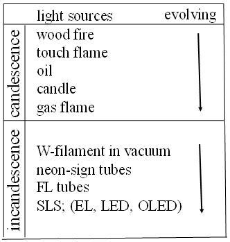
Figure 1. Evolution of candescent and incandescent lamps. SLS is solid lighting sources
The ancient human had the activity in the dark night for 5 million years. About 105 years ago, they had started the illumination of the dark night by the use of the fire flame of the dried woods that were the candescent lamp. The word of the candescence comes from the ancient Greek. The candescence means the fire flame. The fire flames are made with the chemical reaction of the heated materials with the oxygen in air. The chemical reactions with the oxygen release the heat by the change in the entropy. The temperatures of the fire flames determine the illumination levels. The candescent lamps evolved with the time of the human activity for 5 million years. The candescent lights by the dried wood had changed to fats, oils, and natural gases. Figure 1 shows the evolved candescent lamps. After the finding of the invisible electrons and atoms in the solids and in the gas on late 1700s, the lighting lamps have changed to the incandescent lamps that generate the visible lights as the consequence of the moving electrons in the metals, compounds, and gases as shown in Figure 1. The metals, solids, and gases are composed with atoms that float in vacuum with the different conditions. The incandescent lamps generate the visible lights by the moving electrons in either one of metals, compounds, or gases. The popular incandescent lamps at the present time are (i) tungsten (W) metal filament lamps, (ii) light emitting diode (LED) lamps, and (iii) fluorescent (FL) lamps. We have the brief summaries of the lighting mechanisms of three lamps.

2.1. Tungsten (W) Filament Lamps

Nerveless metals are observed by the naked eyes, metals are composed with densely arranged metal atoms in diameter at around 3 x 10⁻¹⁰ m that are invisible by the naked eyes. By the invisible atomic level, the metal atoms at the lattice sites are bounding with the electrons in the upper electric shell of the metal atoms. The bonding shell of the metallic atoms is either one of (s, or p, and d shells) by the given metal atoms. For example, the most popular metal filament lamps are the tungsten (W) filament lamps. The bonding shell of the W-atoms is the 5d10 electron shell that has the capability of 10 electrons. The most upper shell of the W-atom is not completely filled by the electrons. The 5d10 shell of W-atom has only 4 electrons, 5d4. Consequently, the bounding shell of each W-atom at the lattice sites has 6 vacancies in the bonding shell. Each W-atom in metal has the capacity of the acceptance of 6 moving electrons in the bonding shell. Consequently, the electrons in the metals move on in the inside of the bonding 5d4 shell of the W-atoms, as illustrated in Figure 2 (A). No vacuum space between W-atoms at the lattice sites involve in the moving electrons in the W-filament metal.
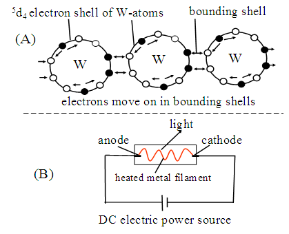
Figure 2. Schematic illustrations of 4 bounding electrons and 6 empty electrons in 5d10 electron shell of W atoms (A) and lighting W-filament lamp by Joule Heat under DC power source (B)
Each electron in the 5d4 shell of W-atom thermally vibrates at lattice sites. Naturally, the moving electrons in the W-metal inevitably receive the thermal perturbation from the W-atoms at the lattice sites. The thermal perturbation generates the electric resistance (R) to the moving electrons. The moving electrons in the W-filament have the electric resistance that generates Joule Heat (= I2R). Where I is electric current and R is electric resistance. Naturally, the W-metal lamps are heated by the Joule Heat. The lights of the W-filament lamps come from the heated filament at the high temperatures by the Joule Heat, like as the Sun. Figure 2 (B) schematically illustrates the lighted W-filament lamp. The energies of the photons from the heated W-filament widely distribute from the ultraviolet lights to the infrared lights. Consequently, we cannot calculate the quantum efficiency (ηq) of the W-filament lamps. The ηq is given by the ratio of the numbers of the visible photons (lights) from the lamps per one moving electrons per second in the considered lamp. The light intensity from the W-filament is solely determined by the heated temperatures. Accordingly, the W-filament lamps consume the large amount of the electricity with the heat of the W-filament to the high temperatures. There is no room to reduce the electric power consumption, WDC or Wact, of the W-filament lamps. The evaporation of the heated W-filament determines the operation life shorter than 500 hours. We may have a conclusion that the W-filament lamps do not have a capability for the contribution to the Green Energy Project by United Nations.

2.2. LED Lamps

LED lamps use semiconductor crystals that atoms are tightly bounded with electrons in upper electric shell of atoms. The bounding of the semiconductors is called as the covalent bonding of the atoms. The semiconductor crystals have well studied with the Si crystals as the semiconductor elements. The covalent bonding in Si4+ crystal does not have the vacancy of the electron in the bonding shell. Consequently, the pure Si crystal does not have the moving electrons in neither the bonding shell nor the vacuum space between Si4+ at lattice sites. The pure Si crystal is the electric insulator. As the Si crystal contains a small amount P5+, each P5+ has one extra electron in the bonding shell. One extra electron in P5+ stays in the narrow vacuum space between Si atoms at lattices. The extra electrons in the Si(P) only move on in the narrow vacuum space between lattice sites, giving rise to the n-type semiconductor. As the Si crystal contains a small amount B3+, the covalent bonding lucks one bonding electron (i.e., hole), giving rise to the p-type semiconductor. The p-type semiconductor actually picks up one electron from the narrow vacuum space between Si at the lattice sites. Figure 3 illustrates the covalent bonding of Si crystal and formation of n-type and p-type semiconductors.
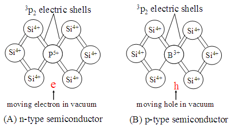
Figure 3. Schematic illustrations of n-type and p-type Si semiconductors
The electrons in the n-type and p-type semiconductors move on in the vacuum space between Si atoms at the lattice sites as the metal electrodes at both ends have the voltages above the threshold. Figure 4 schematically illustrate the moving electrons in the narrow vacuum space between Si atoms at lattice sites. The Si atoms thermally vibrate at the lattice sites. The thermal vibration extends to the vacuum between Si at the lattice sites. Consequently, the moving electrons in the vacuum between Si atoms inevitably receive the thermal perturbation from the thermally vibrating atoms at the lattice sites. The thermally disturbed electrons in the crystal inevitably have the Joule Heat (= I2R) in the operation, resulting in the heat up the temperatures of the operation. The moving electrons in the Si semiconductors always lose some amount of the kinetic energy by the Joule Heat.
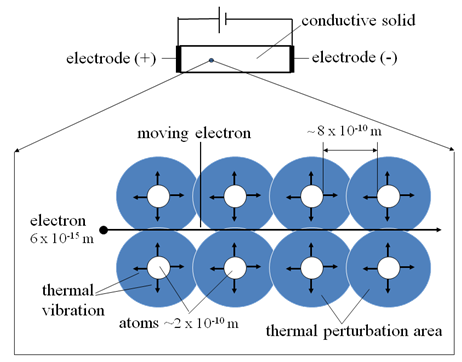
Figure 4. Schematic illustrations of moving electron in vacuum between atoms at lattice sites and thermally vibrating atoms at lattice sites
The LED lamps use III-V semiconductor. The bonding conditions of III-V atoms are fundamentally the same with the Si crystal. The pure III-V compounds are the electric insulators. The n-type and p-type III-V compounds are made by the addition of the small amount of the proper impurities. The extra electrons and holes only move on in the narrow vacuum between atoms at lattice sites, as the illustration in Figure 4. Here arises a problem in the study on the moving electrons in the semiconductors. In the past, the band model has been used for the study on the solid compounds. The band model consists with the valence and conduction bands. We may not prove the existence of the band model scientifically. For instance, you may assign the upper band as the electric conduction band. However, the wide bands are caused by the overlapped wave function from the neighbor atoms that do not give the moving paths of the electrons in the bonding shell in the solids. The electrons in the solids never move on in the orbital shell of the covalent bounding. We cannot use the band model for the analysis of the LED lamps.
The LED lamps use the moving electrons in the n-type III-V compound and the moving holes in the p-type III-V compound respectively. The moving electrons in the n- and p- type III-V compounds never generate the lights. For the generation of the lights, n- and p-type compounds are joined with the junction, as illustrated in Figure 5 (A). The removal of the electrons and holes from the compound respectively requires the threshold voltages (depletion at junction) as shown in Figure 5 (B). The junction (depletion) in Figure 5 (B) is essential for the operation of the jointed semiconductors.
Figure 5. Illustrates formation of LED lamp that joins n-layer and p-layer are joined with junction layer (A), and characteristic property of junction in V-I curve in operation (B)
The light generation of the LED lamps requires the luminescence centers. As the junction contains the luminescence centers, the activity of the luminescence centers in the junction starts the captures of the electron from n-type semiconductor. The recombination process of the electron and hole in the luminescence center is accomplished by the capture of the hole from p-type layer. The recombination of a pair of the electron and hole at the luminescence center generates one visible light (photon) at the given spectral wavelength, and returns to the original recombination center. The numbers of the emitted photons from the junction relate to the numbers of the injected electrons from the anode electrode. An overlook in the study on the LED lamps is the energy loss of the moving electrons and holes by (i) the removal of the electron and hole from the bounding III-V compounds to the vacuum between lattice sites as shown in Figure 5 (B), and (ii) the Joule Heat in n- and p-semiconductors, as shown in Figure 4. The luminescence centers are inactive in the depletion range in the operation. The figure of the merit of the incandescent lamps is given by the numbers of the generated visible photons by one moving electron that is the quantum efficiency, ηq. The quantum efficiency of the LED lamps is less than 1.0; ηq< 1.0. There is a reported ηq = 0.8 [3], but it is too high. Many reported ηq is around 0.5. We take ηq ≈ 0.5 for the calculation of the emitted visible photons from the LED lamps.
Another limitation of the operation of the LED lamps is the stability of the luminescence centers (e.g., impurities) in the junction that are at around 70°C [4]. Above 70°C, the light output from the LED lamps suddenly decreases with the temperatures. The LED lamps should operate with the temperatures below 70°C. The LED lamps are operated with the constant DC voltage at 2.8 V. Anyway, we may calculate the electric power consumption from the electric current in the operated LED lamps.
The LED lamps emit the visible photons at the given wave length. Accordingly, we may calculate the required numbers of the visible photons for the illumination purpose. However, the required electric current of the practical LED lamps for the illumination purpose has ever calculated in the published reports. As already described, the comfortable illumination level of the rooms is given by the widely scattered lights, like as the overcastting sky. The comfortable illumination level on the furniture in the room is given by either the luminance (300 cd, m-2) or illuminance (300 lm, m-2), corresponding to the 1025 visible photons (m2, s)-1 [1, 2]. As already mentioned, the performance of the LED lamps is never evaluated by the luminous efficiency (lm, W) that is for only study on the colorimetry. The LED lamps are the illumination source. The power consumption of the LED lamps should take the WDC or Wact of the electric driving circuits. The LED lamps generate one visible photon by the recombination of the pair of electrons and hole. We may calculate the required electric current in the lighted LED lamps from the generation of the 1025 visible photons (m2, s-1) from the LED lamp. The DC electric current of 1 A is given by 1 Coulomb per second. One electron has 1.6 x 10⁻¹⁹ Coulomb. The numbers of the electrons in 1A are 6 x 10¹⁸ electrons per second {= (1.6 x 10⁻¹⁹ Coulomb, sec)-1}.
We may calculate the required electric current of the practical LED lamps (ηq = 0.5) for the illumination of the room in 1m2. The required electric current in the LED lamps is 3.2 x 10⁶ A (= 1 x 1025 electrons x 2 x 1.6 x 10-19 Coulomb per second), independent on the applied voltage to the LED lamps. The practical size of the dais of each commercial LED lamp is around (1 x 10⁻³ m)2 that gives the area of 10-6 m2 (= 1 mm2). If a practical LED lamp is produced with the arrangement of 3 x 10⁶ LED lamps on a given board (e.g., 1 m2) without the space gap between LED daises, the LED lamp on the 1 m2 board should illuminate comfortably the furniture in the 1 m2 room.
We may calculate the electric power consumption WLED of the 3 x 10⁶ LED lamps on the given board in 1 m2. The LED lamps are operated by the application of the DC 2.8 V. The calculated WDC (= VI) is 1.8 x 10⁷ watt (= 2.8 V x 2 x 3.2 x 106 A). The practical LED lamps in the 1 m2 board consume WDC = 1.8 x 10⁷ watt per second. The half of them (9 x 10⁶ watt) is consumed by the Joule Heat (= I2R). The Joule Heat inescapably heats up the LED lamps to the temperatures higher than 70°C. Unfortunately, we cannot find the solution of the reduction of the huge WDC = 1.8 x 10⁷ watt of the LED lamps. Consequently, we cannot operate the LED lamps with the DC voltage.
The drilled study on the CRT may give a suggestion to reduce the large power consumption to significantly low level [5]. According to the study on the illuminance (lm, m-2) of the lighting phosphor screen of the CRT, there is a way for the reduction of the WDC of the lighting LED lamps that use the after image effect of the eyes. One may have the images with the same luminance (330 cd, m-2) on the phosphor screen in CRT with the modified lighting cycles. Figure 6 shows the results of the (a) spot luminance, (b) scanning lines in the limited screen and (c) by the reciprocal illumination of the defined area of the screen. Accordingly, if the total LED lamps on the given dais are operated by the field-scan of the pulses that have 2.8 V, your eyes may detect the required light images under the operation by the AC driving circuit. As the LED lamps are operated with the field scan of the pulses at 2.8 V, the LED lamps should be operated with the AC driving circuit. Accordingly, the power consumption of the LED lamps is given by the active AC power consumption, Wact, instead of the WDC. In general, the Wact is higher than the WDC; Wact > WDC. We do not know the Wact in the practical LED lamps. We take the WDC in the following calculations.
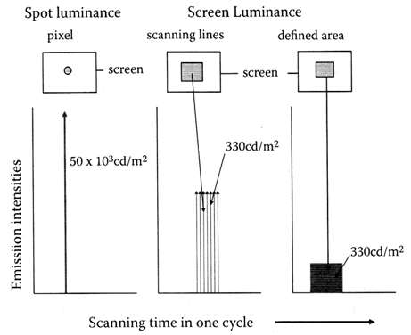
Figure 6. Schematic illustration of same luminance from phosphor screen under different lighting modes under irradiation of electron beam that is a spot, scanning line, and defined area (flame scan) [5]
As the operation of the LED lamps modifies to the flame scan of the pulse at 2.8 V by the AC driving circuit [6], the LED lamp emits the half cycle as the electrode of the n-type semiconductor has the positive potential. The LED lamps do not emit the lights for the subsequent half cycle of the pulse that the n-type semiconductor has the negative potential. We may experimentally determine the operation cycles of the pulses for the no flicker of the lighting source. From the experiments of the projected images on the screen, the recommended pulse cycles for the illumination of the room are above 100 Hz for the LED lamps. The actual lighting cycles are 50 Hz. The WDC of the illumination of 1 m2 room may reduce to 10-4 WDC that is 900 watt (= 9 x 10⁶ watt x 10-4), excluding the power consumption of the AC driving circuit. The ordinal room size is not 1 m2. The ordinal room size in the house is usually 30 m2. The required WDC for the illumination of the 30 m2 by the LED lamps is 2.7 x 10⁴ watt (= 900 m-2 x 30 m2) ≈ 30 k-watt. It should be noted that above calculations are made with the no gap between the daises. The practical LED lamps have the gap between the daises. The practical LED lamps consume the WAC higher than above calculations.
By the calculations based on the material science and optical science, one may allow us to have a conclusion that the production conditions of the LED lamps have already optimized scientifically. The light output from the LED lamps is determined by the numbers of the injected electrons from the anode of the LED lamps. Since the moving electrons in the III-V semiconductors do not have the superconductor, the numbers of the output of the visible photons from the LED lamps are regulated with (a) low ηq ≈ 0.5, and (b) threshold operation temperature at 70°C. We cannot figure out the claimed advantage of the LED lamps from Japan as the energy saving incandescent lamps scientifically. The LED lamps have no room for the contribution to the Green Energy project (COP) on the world as the science, even though someone claims it. For the claim of the energy saving light source of the LED lamps, the claimers should show the reduction of the operation power consumption by the scientific evidence. Then, we may evaluate again the improved LED lamps.

2.3. Fluorescence (FL) Lamps

Other incandescent lamp is FL lamp that uses moving electrons in wide vacuum space between Ar atoms. The Ar gas pressure in the established FL lamps is around 930 Pa (7 Toll). The largest difference is the size of the FL lamps. The commercial 40W-HCFL lamps have the diameter of 3.2 x 10⁻² m (T-10) with 1.2 m long. The next large difference is the vacuum space between Ar atoms (10-6 m) in the FL lamps, as compared with 10-8 m of LED and W-filament lamps. Accordingly, the conditions of the moving electrons in FL lamps quite differ from the conditions of the LED and W-filament lamps. Figure 7 shows photograph of lighted FL lamps (A) and structure of FL lamps (B). The commercial FL lamps are composed with six parts. They are (i) vacuum-sealed glass tube, (ii) BaO particles on the W-filament coil as the electrodes at the both ends of FL lamps, (iii) Ar gas pressure at 930 Pa (= 7 Torr), (iv) vapor pressure of Hg atoms at around 0.1 Pa (= 1 x 10⁻³ Torr), (v) opaque phosphor screen on inner glass wall that transduces the UV lights to visible lights and (vi) FL lamps are operated with the AC driving circuits.
The FL lamp had invented by F. Mayer on 1928 [7]. Since then, the many scientists and engineers have studied on the FL lamps for nearly 90 years. After many trials, they have developed the hotcathode FL (HCFL) lamps as the favorable incandescent lamps. The developed HCFL lamps brilliantly light up by the moving electrons in the vacuum space between floating Ar atoms in vacuum. They paid their attention to the optimization of the developed HCFL lamps for the practical use. Their studies have summarized in many publications and Handbooks. The typical publications and Handbooks are references [8-11]. With the large annual production volume and many technical works, it has believed that technologies involved in the commercial HCFL lamps have well established as the mature technologies.
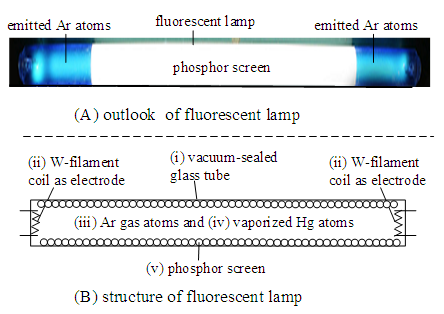
Figure 7. Photopicture of outlook of HCFL lamp (A) and structures of HCFL lamps composed with six parts (B)
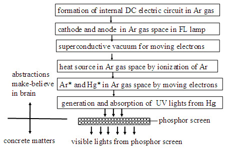
Figure 8. Illustration of abstraction and concrete matters involved in operation of FL lamps
Recently, we have studied the HCFL lamps. The study faces many difficulties for the understanding of the established results of the HCFL lamps. The difficulties come from the hypotheses for the operation mechanisms of the HCFL lamps. The hypotheses have not clarified by the scientific proofs. All of the hypotheses are made with the invisible items by the naked eyes. The items of the hypotheses belong to the abstraction. The modern science after 1800 has developed by the scientific proofs of the invisible items.
As shown in Figure 8, the concrete matters and abstractions involve in the study on the lighting mechanism of the HCFL lamps. The established HCFL lamps have well studied with the concrete matters, but the technologies on the abstraction have made with the hypotheses without the proof scientifically. In this report, we must clarify all of the hypotheses in the lighting mechanisms of the HCFL lamps. Then, we have studied the details of the features of the FL lamps. Finally, we have found the coil-EEFL lamp that is ultimate incandescent lamps with the operation of WDC = 0. The developed coil-EEFL lamps brilliantly light up with the WDC = 0 under the external DC driving circuit. The brilliant lighting of the coil-EEFL lamps with WDC = 0 will contribute to the Green Energy Project of United Nation.
2.3.1. Fundamentals of Ar Gas Space between Ar Atoms in Commercial FL Lamps
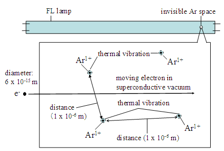
The great advantage of the FL lamps comes from the use of Ar gas of the pressure at 930 Pa (7 Torr). The melting point of Ar atoms is -189°C, and boiling point is -186°C. At the temperatures above the boiling point, Ar atoms in diameter of 4 x 10⁻¹⁰ m (= 4 Å) only exist as gas phase. The temperatures of the Ar gas in the lighting FL lamps are higher than the room temperatures. The inner volume of the commercial 40W-HCFL lamps (T-10) in 1.0 m long is 7 x 10⁻⁴ m3 {= πr2 x l = (1.5 x 10⁻² m)2 x π x 1.0 m). Huge numbers of the Ar atoms in the diameter in 4 x 10⁻¹⁰ m float in the vacuum in the FL lamps.
We may calculate the numbers of Ar atoms in the FL lamp at pressure of 930 Pa (7 Torr). The numbers of the Ar atoms in a given FL lamp is calculated from the Boyle-Charles law (PV = mRT) and Avogadro’s numbers. Where P is pressure at atmosphere, V is inner volume of the FL lamp, m is mole, R is gas constant (8.32 J/K. mol), and T is temperature by oK. The rounded Ar gas pressure (P) in the FL lamp is ≈ 0.01 atmospheres {= 7 Torr x (760 Torr)-1}. RT = 2.5 x 10³ Joule (= 8.32 J/K x 300 oK). P/(RT) = 4 x 10⁻⁶ {= (1 x 10-2) x (2.5 x 103)-1}. Mole of the Ar gas in the FL tube is given by {m = V x P(RT)-1} that is 2.8 x 10⁻⁹ mole (=4 x 10-6 x 7 x 10-4 m3). The numbers of the Ar gas atoms in the FL lamp are calculated by the Avogadro’s number (6 x 10²³ per mole). The numbers of Ar atoms in the FL lamp are calculated as 1.7 x 10¹⁵ Ar atoms (= 6 x 1023 x 2.8 x 10-9 mole).
The separation distance of the Ar atoms in the FL lamps is calculated by the unit volume (m3). The numbers of the Ar atoms in m3 are 2 x 10¹⁸ atoms per m3 {= 1.7 x 1015 x (7 x 10-4 m3)-1}. The Ar atoms arranged on one side of 1 m3 are 1.2 x 10⁶ Ar atoms m-1 (= (2 x 10¹⁸ m-3)1/3. The rounded average separation distance between Ar atoms on the side of the cubic is 1 x 10⁻⁶ m {= 1 m x (1.2 x 106)-1} ≈ 1 μm. The vacuum space between 1 μm is much wider vacuum space of the moving electrons in the diameters 5.6 x 10⁻¹⁵ m. Figure 9 illustrates the calculated results. The calculated vacuum space (10-6 m) between Ar atoms inform us that the electrons in the lighted FL lamps may move on in the very wide vacuum space, as compared with the moving electrons in the solids (10-9 m vacuum space). Therefore, we cannot take the concepts of the moving electrons that have been determined by the solids and metals. The diameter of the Ar atoms is 3.8 x 10⁻¹⁰ m (= 3.8 Å) that is very small size as compared with the separation distance between Ar atoms, 1 x 10⁻⁶ m. The individual Ar atoms float in vacuum with the very large separation distance from neighboring Ar atoms, as illustrated in Figure 9. The large separation distance indicates that the Ar atoms in FL lamp never bind up with the orbital electrons of the neighboring Ar atoms. Each Ar atom in the FL lamps isolates each other in the vacuum. Isolated Ar atoms in the vacuum thermally vibrate at the floating position. The volume of the thermal vibration of each Ar atom at the room temperature is confined in the diameter of 8 x 10⁻⁹ m (8 nm). Consequently, the moving electrons in the wide vacuum space between Ar atoms in FL lamps do not have the thermal perturbation (electric resistance, R) from the thermally vibrating Ar atoms at the floating position. The electrons move on in the wide vacuum space without R. The vacuum space between Ar atoms provides the superconductive vacuum for the moving electrons in the FL lamps. The superconductive vacuum is a great advantage of the moving electrons in FL lamps.
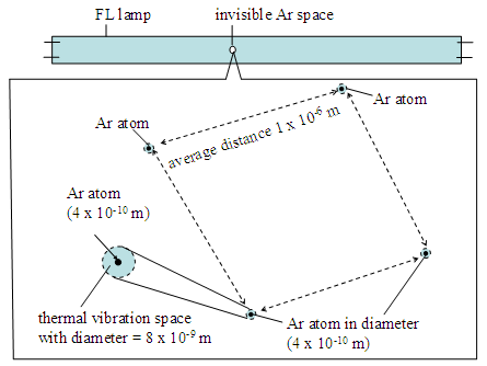
Figure 9. Schematic illustration of distribution of floating Ar atoms in vacuum in FL lamps. Individual Ar atoms in diameter at 4 x 10⁻¹⁰ m isolate each other with distance 1 x 10⁻⁶ m. Each Ar atom in diameter at 8 x 10⁻⁹ m thermally vibrates at floating position with volume of 8 x 10⁻⁹ m diameter
Here we have overlooked an important item. The conditions shown in Figure 9 are the lighted FL lamps. Unlighted FL lamps have another condition. Each floating Ar atoms fill up the orbital shells by the electrons. The electric field from the orbital electrons in Ar atoms extends to the vacuum between Ar atoms. The vacuum space between Ar atoms fills up by the negative electric field from the electrons in the orbital shells of the floating Ar atoms in the vacuum.
We may confirm the electric field between isolated Ar atoms in the FL lamps by the measurement of the optical absorption spectrum of the Ar atoms in the unlighted FL lamps. We may detect the strong and sharp absorption lines of the intrinsic energy levels. We also detect many weak absorption lines at around the intrinsic energy levels. The sharp absorption lines indicate the isolation of individual Ar atoms in the FL lamps. Many weak absorption lines at around the intrinsic energy levels have assigned as the splitting of the intrinsic energy levels. It is well know that as the atoms in the gas are under the external electric field, the intrinsic energy levels split to the sublevels. The split sublevels are called by the Stark Effect. If the atoms are under the external magnetic field, the sublevels under the Stark Effect further split to the sublevels that have called by Zeeman Effect. Fortunately we do not detect the split sublevels by the Zeeman Effect. We do not consider the magnetic field in the vacuum in the study on the lighted FL lamps.
The spectral measurements inform us that the vacuum space between floating Ar atoms in the unlighted FL lamp fills up with the negative electric field. This is an essential problem in the study on the lighting of the FL lamps. The cathode metal electrode of the FL lamp cannot inject the electron into the vacuum space that fills up with the strong-negative field. The studies of the FL lamps for nearly 90 years did not consider the negative electric field between Ar atoms. Fortunately, they had empirically developed the hotcathode FL (HCFL) lamps. The HCFL lamps smoothly light up by the application of the hotcathodes. They have believed the hotcathode directly emit the electrons to the vacuum of the Ar gas space. Consequently, the HCFL lamps smoothly emit the light. The emitted HCFL lamps hold the significant advantages as the light sources over the other incandescent lamps. When someone wishes to improve the quality of the established HCFL lamps, he must consider the problems of the negative electric field between Ar atoms. How do break the negative electric field in the Ar atoms for the start of the lighting of the HCFL lamp. If you have learned the established technologies in the publications of the commercial HCFL lamps, you never have a chance of the development of the advanced FL lamps that should not have the superiority over the established HCFL lamps. By the learning of the established information, you never have the development of the science. It has believed that the heated BaO particles on the W-filament coils directly emit the thermoelectron into the vacuum space between Ar atoms in the HCFL lamp. With this reason, we have studied the basic of the electrodes in the established HCFL lamps.
2.3.2. Commercial HCFL Lamps Never Use Thermoelectrons
A most important subject in the study on the FL lamps is the electron source (cathode and anode) in lighted FL lamps. The established concept of the HCFL lamps is similar concept with other incandescent lamps. The attached anode electrode of the HCFL lamp supplies the electrons into the vacuum and the cathode corrects the electrons from the vacuum. This is a wrong assignment of the electron emission. In the vacuum devices, the cathode emits the electrons and anode corrects arrived electrons. If the metal electrodes use in the FL lamp, like as the solid electric devices, the FL lamp do not light up with the ordinal AC driving devices. The vacuum condition of FL lamps closes with the vacuum of cathode ray tube (CRT) and vacuum (radio) tubes (VRT). Then, the developers of the FL lamps have taken the thermoelectron emission of the CRT and VRT to the FL lamp. However, the vacuum pressure of the FL lamps at 900 Pa quite differs from the vacuum at 10-5 Pa (10-7 Torr) of CRT and VRT.
The drilled study on the thermoelectron emission from the heated BaO particles had made with the study on the CRT and VRT. The operation life of the CRT was around 3 to 5 years before 1975. We had extensively studied the heated BaO particles on the cathode metals in the CRT [12]. The heated BaO particles never emit the thermoelectrons into the vacuum. Only heated Ba atoms arranged at top layer on the heated BaO particles steadily emit the thermoelectrons into the high vacuum at the pressures below 10-5 Pa (< 10-7 Torr) for the times longer than 10 years. The heated Ba atoms under the vacuum pressures higher than 10-2 Pa (> 10-4 Torr) quickly damage the capability of the thermoelectron emission. Under the vacuum pressures higher than 1 Pa (10-2 Torr), the Ba atoms instantly damage the capability of the thermoelectron emission.
The commercial HCFL lamps are operated with the Ar gas pressure at around 930 Pa (~ 7 Torr). The heated BaO particles on the W-filament coils in the HCFL lamps never emit the thermoelectron emission into the Ar gas. Furthermore, the produced HCFL lamps always contain the large amount of the residual gases higher than 1 Pa (> 10-2 Torr). The residual gases come from (a) the poor maintenance of the vacuum pumping systems in the production, (b) uneven heating of the FL lamps in the heating furnaces in the production, and (c) poor vacuum sealing process of the pumping tip glass tubes [1, 2]. The residual gases in the commercial HCFL lamps are H2O, CO2, N2, O2, CHn, and other organic gases.
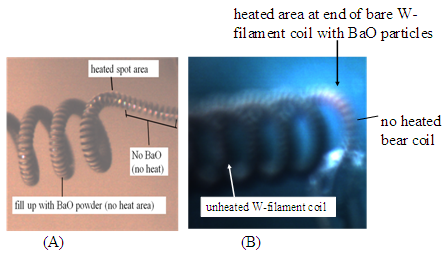
Figure 10. Photographs of produced W-filament coil with ideally packed BaO particles (A), and large unheated area and heated small area in W-filament coil in working HCFL lamp under 40 kHz (B). Experiments are made with HCFL lamp without phosphor screen
From the study of the CRT and VRT, it can say definitely that the commercial HCFL lamps never use the thermoelectrons from the heated BaO particles on the W-filament coils. We have found that the commercial HCFL lamps actually use the formation of the high temperature Ar corona space (HTACS) at above 50°C [13]. The HTACS is the fourth generation electron source (4G) of the lighted FL lamps [14]. With this reason, we have studied the basic of the role of the electrodes in the established HCFL lamps. The HTACS in the commercial HCFL lamps cannot observe by the naked eyes because the HCFL lamps entirely cover up with the opaque phosphor screen on inner wall of the FL lamps. For the study of the W-filament coil with the BaO particles, we have studied with the HCFL lamp without the phosphor screen.
We have observed the direct evidences with the working W-filament coils with the BaO particles under the optical microscope. Figure 10 (A) shows photograph of the ideal W-filament coil with the BaO particles for the application to the commercial HCFL lamp. Figure 10 (B) shows the working W-filament coil in the working HCFL lamp under the AC driving circuit with 40 kHz. The produced W-filament coils with the BaO particles always have the bear W-filament coil at the both ends as shown in Figure 10 (A). The photograph in Figure 10 (B) definitely shows that the long W-filament coil with the BaO particles are dark, indicating that the long bear W-filament coil with the BaO particles never heat up to the temperature above 400°C. Accordingly, the W-filament coil with the BaO particles never emits the thermoelectrons in the operation of the HCFL lamps. The heated area is the small area of the bear spot of the W-filament coil at one side, not the both sides, at which have the small amount of the heated BaO particles. The temperature of the heated bear spot is around 500°C that does not emit the thermoelectron. The temperatures at the bear filament change with the operation frequencies. By the operation of the 50Hz, the temperature of the bear spot of the W-filament coil is higher than 700°C, and the low temperature with the operation of 40 kHz. The operation life of the W-filament coils is determined by the evaporation of the W-atoms from the heated bear spot; the short operation life with the 50 Hz operation and a long life with 40 kHz operation. The results in Figure 10 (B) inform us that the BaO particles on the W-filament coil never emit the thermoelectrons into the Ar gas space. The thermoelectron emission from the heated BaO particles on the W-filament coil is a figment by your imagination in the study on the HCFL lamps.
We have experimentally confirmed that the lighting mechanisms with the W-filament coils with BaO particles. The confirmations are made with the use of the unlighted HCFL lamps with different lengths. At first, we have studied the appearance and disappearance of the lights from the Ar gas space in the HCFL lamps. The FL lamps do not have the phosphor screen for the observation of the lighted Ar atoms in the tested FL lamps. The experiments are made with the applied AC voltages of the lighted HCFL lamps in the outer diameter at 2.2 x 10⁻² m (T-7) as a function of the lengths from 0.2 m to 1.2 m long. The used frequency of the AC driving circuit is 30 kHz. Figure 11 shows the experimental results. The upper curve (appearance of light) gives the starting AC voltages of the light of the tested HCFL lamps. After lighting for 1 minute, the applied voltages gradually reduce to the disappearance of the light from the lighted HCFL lamps. The voltages of the appearance and disappearance are a linear function of the lengths of the HCFL lamps with the same slope that is given by 230 V per lengths (m-1). The slope (230V/m) gives the strength of the electric field between electrodes of the W-filament coil with the BaO particles. There are the threshold voltages for the appearance and disappearance of the light. The AC voltages (Vlight) of the appearance and disappearance of the lights from the HCFL lamps are expressed by
(1)
The threshold voltages (Vth) are respectively 190 V for the appearance and 75 V for the disappearance. As the AC voltage of the appearance, we have observed the small area of the bear W-filament coils surely heat up like as the result shown in Figure 10 (B). Eq. (1) is only applicable to the 4G electron source.
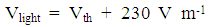
Figure 11. Experimental results of appearance and disappearance voltages of lights from HCFL lamps under inverter driving circuit (30 kHz), as function of lengths of HCFL lamps
We have a question about the slope of the Vth = 190 V for the bear spot of the W-filament coils of the lighted HCFL lamps. Then, we have studied with the AC voltages slightly higher than the disappearance AC voltage to the unlighted HCFL lamps. For example, we applied to 300 V (30 kHz) to the unlighted HCFL lamp in 1.0 m long. The tested HCFL lamp did not light up under 300 V. For the generation of the light of the Ar atoms in the tested HCFL lamp, we have slowly approached the active Teslar Coil to the tested HCFL lamp. As the weak spark from the Teslar Coil reaches on the unlighted HCFL lamps, the unlighted HCFL lamps instantly light up with the normal illuminance. The light of the HCFL lamp starts by any positions of the spark of the Teslar Coil on the unlighted HCFL lamp. The spark from the Teslar Coil indicates the ionization of the atoms in air (mainly N2 and O2) at the pressure 105 Pa (760 Torr). The Ar atoms in the testing FL glass tube contains Ar gas pressure less than one hundredth of the air pressure (102 Pa = 7 Torr). Accordingly, the Ar atoms in the unlighted HCFL are ionized with the electric field of the spark of the Teslar Coil. Figure 12 illustrate the configuration of the experiments by the Tesla Coil. Then, we take out the Teslar Coil from the lighted HCFL lamp, the HCFL lamp continuously lights up until turns-off of the AC driving circuit. We obtain the same results with the different lengths of the HCFL lamps from 0.2 m to 1.2 m longs. The experiments of Figure 12 are made with the W-filament coils with the BaO particles shown in Figure 10. If the HCFL lamps have the W-filament coils without the BaO particles, you never obtain the lighted HCFL lamps. The results in Figure 12 surely indicate that the ionization of the Ar atoms in the HCFL lamps triggers the start of the unlighted HCFL lamps that have the heated spot at the bear W-filament coils of the HCFL lamps.
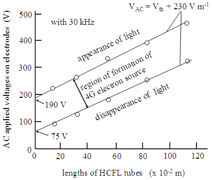
Figure 12. Illustration of experimental arrangement for lighting of HCFL lamps in 1.0 m long under AC 300V with 30 kHz by Teslar Coil
The experiments shown in Figures 11 and 12 inform us the importance of the heat of the bear spot of the W-filament coil with the BaO particles shown in Figure 10 (A). The required conditions for the lighting of the HCFL lamps are the independent on the lengths of the W-filament coils and on the amount of the BaO particles on the W-filament coils. The required condition is the ionization of the Ar atoms in the unlighted HCFL lamp.
2.3.3. Incorrect Determination of AC Electric Power Consumption, Wact, of Lighted HCFL Lamps
We back to the established data of the electric power consumption of the HCFL lamps in the published papers and handbooks. The developers of the HCFL lamps for the last 90 years did not well understand the lighting mechanisms of the HCFL lamps. Fortunately, they had empirically found the HCFL lamps in any lengths brilliantly light up with the AC driving circuit of 50 Hz (or 60 Hz). Now the HCFL lamps are operated with AC inverter circuits with the frequencies higher than 30 kHz. The developers of the HCFL lamps had concentrated the lighting lamps that allowed the mass production. According to their results of the HCFL lamps, they have obstinately believed thermoelectrons from the heated BaO on the W-filament coils. Then, they made the energy share diagrams of the working HCFL lamps as shown in Figure 15. The items in Figure 15 look like well analyze the lighting mechanisms of the HCFL lamps. However, there are many questions for the determinations. For instance, input power for the generation of the light of the HCFL lamp is 40 watt. For the confirmation of the electric power consumption of the 40W-HCFL lamp, we have analyzed the power consumption of the commercial 40W-HCFL lamp.
Figure 14 illustrates the ballast AC driving circuit of the commercial 40W-HCFL lamp and waveforms of the electric current at the AC driving circuits. The ballast circuit is composed with two parts that are the choke coil and the HCFL lamp. We have detected the sine waveform at each component, except for the electrodes of the HCFL lamp. Here arises a misunderstanding of the evaluation of the waveform at the electrodes of the HCFL lamps. They have believed that the electrode (cathode) of the HCFL lamps detects the thermoelectron emissions into the Ar gas, and that the electrode (anode) at other side corrects arrived electrons from the Ar gas. This is a wrong assignment. Furthermore, the light from the HCFL lamp is generated by the 40 watt. The determined 40 watt at the electrodes does not relate to the energy for the generation of the light from the HCFL lamp.
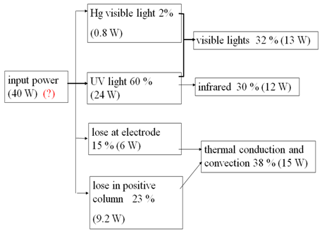
Figure 13. Energy loss diagram of lighted 40W-HCFL lamp under AC operation with 50 Hz [8-10]
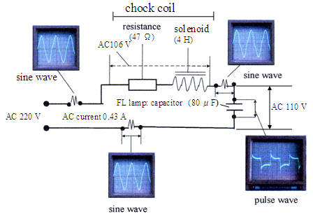
Figure 14. AC driving circuit (ballast) of 40W-HCFL lamp with waveforms at components
As the wave form detected at the electrodes of the lighted HCFL lamp is not made by the flowing electrons in the Ar gas space in the lighted HCFL lamps. The amount of the detected AC current is the AC induced current. More precisely, the detected waveform at the electrodes of the lighted HCFL lamp is the change in the AC voltage at the electrodes of the HCFL lamp. The detected waveform at the electrodes of the HCFL lamps is the same with the waveform detected at the solid capacitor, Csolid. The synchronous changes in the distribution of the electrons in the solids are well studied with the solid capacitors, Csolid. The change of the distribution of the electrons in the solids is made by the deformation of the crystal structure under the AC electric field. As the electrodes of the solid capacitor detect the flowing electrons, the solid capacitor is broken by the arc current. The detected wave form at the electrodes of the HCFL lamp is the wave form of the capacitor (CAr) that forms in the lighted FL lamps. Formation mechanism of the CAr in the lighted FL lamps is ever discussed in the study on the FL lamps. The formation of the CAr in the Ar gas space of the lighted FL tubes is a new concept in the study on the lighted FL lamps. With this reason, we will describe the details of the formation mechanism of the CAr in the lighted FL lamps.
The Ar atom that lost one orbital electron becomes the ionized Ar atoms (Ar1+). Each Ar1+ has an empty electron in the 3p6 shell. The electron in the 3p6 shell of each Ar1+ has the moving space under the change of the electric field from the electrodes of the FL lamps. If the electrodes have the DC electric field, the moving of the electron in the 3p6 shell is made by once. As the electrodes of the FL lamps are operated under the AC driving circuit, the electron in the 3p6 shell of each Ar1+ between the electrodes of FL lamp synchronously moves on the position in the 3p6 shell under the electric field of the AC frequencies, as illustrated in Figure 15. The synchronous movement of the orbital electrons in the 3p5 shell generates the AC induced voltages in the electrodes of the lighted FL lamps. The waveform at the electrodes of the lighted FL lamps shown in Figure 15 is actually waveform in the change in the voltages of the electrodes. The change in the voltage at the electrodes of the AC driving circuit has called by the AC induced current. The electrodes of the HCFL lamps under the AC operation apparently close with the change in the induced voltages. The closeness of the electrodes by the induced current is called as the impedance of the CAr in the AC driving circuit. The electrodes of the FL lamps never close with the flowing electrons.
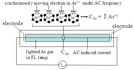
Figure 15. Formation mechanism of capacitor CAr in lighted FL lamp
Now it is clear that the results in the input power (W) in the energy loss diagram in Figure 15 invalid in the analysis of the mechanisms of the lighted HCFL lamps. The input power 40 watt in Figure 15 does not relate with the generation energy of the light in the FL lamps. Therefore, the results in Figure 15 give you a fake story. As if you study the energy lose in the diagram in Figure 13, you will have the erroneous conclusions. This is a typical example that the invention (not innovation) of the new product is made by “the finding of the invalidation of the established results by the study on the advanced science. The innovation is the improvement of the existing products with a few% orders.
One may allow us to examine the results in Figure 14. We have assigned the waveform detected at the electrodes of the lighted FL lamps to the typical waveform of the capacitor CAr. The capacitance of the CAr is calculated as 78 μF {CAr = 0.43 A x (50 Hz x 110 V)-1}. The Wact of the CAr alone is 47 watt (= 110 V x 0.43 A). The choke coil composes with the solenoid (4H) and electric resistance (47 Ω). The Wact at the chock coil is 46 watt. The total Wact of the external AC driving circuit of the lighted 40W-HCFL lamps is calculated as 93 watt (47 + 46 watt). The commercial 40W-HCFL lamps actually consume the electricity at around 90 watts, depending on the producers. Furthermore, the determined Wact (47 watt) at the electrodes of the HCFL lamps does not relate to the generation energy of the lights from the lighted HCFL lamps. The lights from the HCFL lamps are solely generated by the moving electrons in the superconductive vacuum in the Ar gas space in the HCFL lamps. We do not have an instrument that determines the amount of the moving electrons in the Ar gas space in the lighted HCFL lamps.
Similarly, the determined power consumptions at other parts in Figure 13 are also questionable. For instance, we cannot determine (a) the energy of the UV lights inside of the lighted FL tube and (b) the energy lose in the positive column, and so on. As will be described in Chapter 3 in this report, the electrons in the lighted FL lamps move on in the superconductive vacuum in the Ar gas space in the positive column. The electrons in the positive column do not lose the electric energy by the electric resistance (V ≠ RI) with R = 0. Furthermore, the electrons in the lighted FL lamps never step in the Ar gas in the gap between positive column and phosphor screen on the inner wall of the lighted FL lamps. The results in Figure 13 are totally unacceptable results for the study on the FL lamps.
Furthermore, we may find many mysteries that involves in the established lighting mechanism. For an example, the optimized commercial HCFL lamps are produced with the glass tube of the outer diameter in 3.2 x 10⁻² m (T-10). The light output from the HCFL lamps sharply decreases with the narrow diameters less than 2.5 x 10⁻² m (T-8). The HCFL lamps with the diameters less than 2.5 x 10⁻² m emit the dim light. The HCFL lamps in the diameter less than 1 x 10⁻² m do not light up. No explanation has been given for the study on the decrease in the light output in the narrow diameters of the HCFL lamps.
We have studied the moving electrons in the lighted FL lamps. The real lights from the lighted FL lamps do not come from the excited Ar atoms (Ar*). The excited Ar atoms (Ar*) in the lighted FL lamps emit the lights in the sky-blue spectral wavelengths as shown in Figure 7. More precisely, the Ar atoms in the FL lamps emit the line emissions at (428.8, 476.5 and 480.6) x 10-9 m, respectively. But the sky-blue lights from the Ar atoms are not the important light source of the FL lamps. The real light source of the lighted FL lamps is assigned by the excited mercury atoms (Hg*). The Hg* are only generated by the moving electrons in the positive column in the lighted FL lamps. We must know details of the vaporized Hg atoms in the Ar gas space in the lighted FL lamps.
2.3.4. Harmless Mercury (Hg) Atoms in FL Lamps to Human Health
Before the description of the use of the Hg atoms in the FL lamps, we would like to clarify other fake story that is the hazardous mercury (Hg) atoms in FL lamps. In the past 50 years, the annual production volumes of the FL lamps on the world were multibillions each year. There is no report of the brain damage of the people by the Hg atoms. This is because the FL lamps use inorganic Hg atoms. The inorganic Hg atoms are harmless for the human body. Therefore, we can produce the FL lamps as the harmless products for the human health.
The fake story has generated from the Japan. Recently, there is a proposal of the hazardous Hg atoms in the FL lamps from the Japanese Government to the Paris Agreement by the United Nation by using the Minamata disease in Japan. The Minamata disease is actually caused by the uncontrolled drain water from a specified chemical factory to the Minamata Bay. The drained water from the factory contained the organic methane mercury (CH3Hg) that is the dangerous compound in the living mater on the Earth. The Minamata disease is the responsibility of the Japanese Government by the uncontrolled drain water from the chemical factory. The Minamata disease never occurs with melted Hg atoms. According to the very recent TV programs, the Japanese Government confirms the Minamata disease is not caused by the metallic Hg atoms. The Minesota Disease limit in the very small area of the fishing villages at the Minamata bay. The Japanese Government cannot extend the Minesota Disease to the control of other products that use the useful atomic Hg. The atomic Hg droplets are safe for the human health. The Japanese proposal to the United Nation clearly indicates the scientific knowledge of the Japanese Government to the world.
We have carefully studied the biological science of the CH3Hg. We have found the scientific reason why Minamata disease occurs with the persons in the limited small fishing villages at Minamata Bay and the small agricultural villages at around Minamata city. There is no report of the disease from the residents in the Minamata city and other areas in Japan. Why the Minamata disease was limited in the fishing villages and around mountain villages? The disease by the catalytic CH4Hg solution in the fishing village occurs with the organic cycles in the living body on the Earth. As a large amount of the organic CH4Hg solution discharges to the seawater in the Bay, the organic CH4Hg in the light density float in the sea water. The small droplets of Hg atoms have the high density so that the small Hg droplets immediately sediment on the bottom of the water. The bacteria in the sea water first takes the floating organic CH4Hg compounds in to the cells of the bacteria. As the small fishes, shellfishes, and shrimps in the sea of the Minamata Bay eat the contaminated bacteria, the organic Hg, not Hg atom, selectively concentrates in the brain and innards of them. The meats of the small fishes are not contaminated with the organic Hg. When the mother in the fishing villages eats the small fishes without removal of the head and innards of the contaminated small fishes, her body is contaminated with the organic Hg, but the mother does not have the serious trouble in the daily activity. When the mother is pregnant, the brain of the embryos in the mother selectively receives the contaminated organic Hg from the mother. The only brain of the embryos is seriously damaged by the received organic Hg but body is not damage, like as the case of the Ziga Virus. The serious Minamata disease is limited in the new born babies. The residents in Minamata city, who eat the meets of the large fishes with the removal of the head and innards, never have the Minamata disease. If the Japanese Government controls the drain of the organic CH4Hg solution from the chemical factory at start, the Minamata disease never happened in the small fishing villages and around mountain villages at Minamata city. The regulation of the production of the FL lamps by the Japanese Government using the Minamata disease is unacceptable as the biological science. It is said again that the prohibition of the production of the FL lamps by using the poison of Hg atoms by the Japanese Government shows their knowledge of the officers and scientists in Japan to the world.
We have a conclusion after the carful study that Hg droplets in FL lamps are safety for the human health. The characteristic properties of Hg atoms are below: The melting point of Hg atoms is -39°C and boiling point is at 356°C. At around room temperatures, Hg atoms are melted phase (liquid). The melted Hg has a high density of 13.6 x 10⁻³ kg at 15°C. The melted Hg has the large surface tension of 464 (dyne cm-1). The melted Hg forms the droplets in the sizes at around 1 x 10⁻³ m, rather than thin layer or large droplets on the phosphor screen in the FL lamps. The vapor pressure of the Hg droplet at 20°C is 0.1 Pa (= 10-3 Torr) that is 10-6 times of the air (N2 + O2) that is 105 Pa (760 Torr). The density of the Hg droplets is 13.6 g per cm3. The vaporized Hg atoms stay in the bottom in the air atmosphere. With (a) the small droplets, (b) extremely low vapor pressure at room temperature (0.1 Pa), and (c) the high density, there is no report of the disease of the human health by the Hg droplets in the human history for 5 million years. Following is the real story with radon (Rn) in the polluted air.
The dangerous poison gas on the Earth at present time is the radioactive (α-rays) radon (Rn) with the atomic number 86. The melting point of Rn is -71°C, boiling point is -62°C. At the room temperature, Rn atoms are gas phase. The density of Rn is 9.7 x 10⁻³ kg m-3. The polluted air in the big cities on the world contains serious amount of the Rn atoms in air. The Rn in the polluted air selectively and continuously deposits in the bottom of the air. Consequently, Rn continuously and selectively deposits in the bottom air in the holes on the grand. Especially the basement rooms in houses, basement of the large buildings, and underground shopping malls. The vapor of the radioactive Rn is the dangerous gas for the human body in the cities. If the air in the basement rooms is not continuously ventilated with the fresh air, the person who lives in the basement will be slowly and surely damaged the health of the human body by the radioactive α-ray from Rn. The reduction of the Rn gas in the polluted air is the serious problem in the cities on the industrialized countries. The reduction of the electric power generators on the world may reduce the polluted level of Rn in air.
As described above, the use of the Hg droplets in the FL lamps is the safety on the human health. We have found that the FL lamps remain the large room for (a) the significant reduction of the electric power consumption, (b) improvement of the illuminance (lm, m-2) from the phosphor screens, and (c) extremely long operation life. We will challenge the remained subjects that are the revised lighting mechanisms of the FL lamps for the reduction of Rn from the electric power generators on the world.

3. Revised Lighting Mechanisms for Decisive FL Lamp

As described above, the lighted FL lamps hold the decisive advantages that have not figured out in the past for 90 years. After the critical studies of the commercial 40W-HCFL lamps, we have found the latent potential of the decisive advantages of the lighted FL lamps. The FL lamps light up under the coexistence of the disparity of (i) the external driving circuit and (ii) the internal DC electric circuit in the operation [15]. There is no electron flow between external and internal electric circuits. The lights in the FL lamps are only generated by the moving electrons from the cathode to anode in the internal DC electric circuit in the Ar gas at the inside of the FL lamp. The basics of the FL lamps are the formation of the cathode and anode of the internal DC electric circuit inside of the FL lamps.

3.1. Formation of Cathode and Anode of Internal DC Electric Circuit in Ar Gas Space

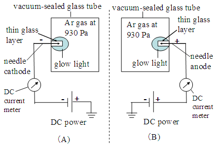
The experimental results in Figure 12 suggest us that the formation of the glow light of the Ar atoms is the trigger of the generation of the cathode and anode of the internal electric circuit in the FL lamps. After formation of the volumes of the glow light in the Ar gas space in the FL lamps, the insulating Ar gas space in the volume of the glow light may instantly break out. With this reason, we have made the volume of the glow light in the Ar gas space without the Teslar coil. The experiments are made by the volumes of the glow light on the needle metal electrodes in the vacuum-sealed glass tubes.
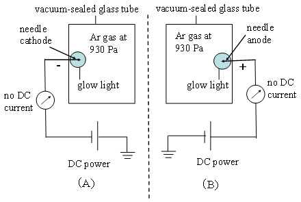
Figure 16. Experimental results of formation of volume of glow lights at around needle electrodes in Ar gas (930 Pa = 7 Torr) in vacuum sealed glass tubes. Needle electrodes respectively have negative potential (A) and positive potential (B) at 2 kV
We have taken two vacuum-sealed glass tubes. Each glass tube contains the Ar gas at 930 Pa (~ 7 Torr). The needle metal electrode installs in each glass tube. Figure 16 shows the experimental configurations. The negative and positive DC voltages respectively apply to the needle electrodes. As the voltages of the needle electrodes below DC 950 V, the needle electrodes do not have the glow lights. When 1.0 kV DC voltages apply to the needle electrode, the volumes of the glow light on the needle electrodes suddenly appear in the separate glass tubes (A) and (B). As the plate electrodes install in the glass tube, the glow light never appear in the Ar gas space with DC 10 kV. The size of the volumes of the glow light does not change with the applied voltages up to 10 kV that we have tested. The DC current meters at the electrodes show no electron flow, indicating that the volume of the glow lights is formed by the electric field from the needle electrodes.
The volume of the glow lights contains ionized Ar atoms (Ar1+), excited Ar atoms (Ar*), free electrons (e-) and Ar atoms. Only Ar* among them emits the sky-blue lights that are visible by the naked eyes. We can use the sky-blue light as the monitor of the formation of the volume of the glow light. The attached DC current meter at the electrodes shows zero electric current, indicating that the volumes of the glow light are only formed by the electric field from the needle electrodes. The thickness of the volume of the glow light on the needle electrodes is about 3 x 10⁻³ m. The volume of the glow lights does not change with the applied voltages to the electrodes. On the other hand, the light intensities of the glow light increase with the applied DC voltages. Thus, we have confirmed the formation of the volumes of the glow light on the needle electrodes in the Ar gas without the electric current from the needle electrodes.
The next experiments are made as whether the volumes of the glow light on the needle cathode act as the cathode and anode in the vacuum-sealed glass tube that contains the Ar gas. We set the needle cathode electrode at one side and the plate anode electrode at other end in a vacuum-sealed glass tube that contains Ar gas at 930 Pa (7 Torr). The reason of the use of the plate anode is collection of all scattered electrons in the Ar gas space. The DC voltage at 3 kV applies to the electrodes. The Ar gas space between the volumes of the glow lights on the needle cathode and plate anode brilliantly emits the sky-blue light with the triangle, as shown in Figure 17. The volume of the glow light at the needle cathode certainly works as the electron source in the Ar gas space. The DC current meters at the cathode and anode surely have the same amount of the DC current at 3 x 10⁻⁴ A. The observed results definitely indicate that the volume of the glow light at the needle cathode certainly supply the electrons to the Ar gas space and plate anode collects all of the arrived electrons from the Ar gas space. The results indicate that the volume of glow light and metal electrode electrically connect in the test glass tube. There is no amplification of the moving electrons by the cascade of the electrons in the Ar gas space. We detect same amount of DC current with the electrodes at both sides of the test tube. The spreading of the lights in the triangle is caused by the formation of the electric field, FDC, between the needle cathode and plate anode. The conclusion has confirmed by the setting of the needle anodes in the glass tube.
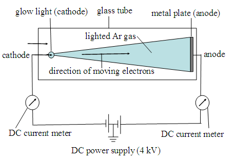
Figure 17. Illustrates flow of electrons from the cathode of glow light to plate metal anode
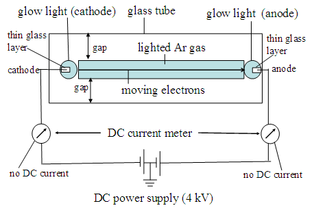
Figure 18. Lighted glass tube which cathode and anode are formed by volume of glow lights on metal electrodes
The needle cathode and anode electrodes set the glass tube, as shown in Figure 18. We surely detect the narrow lighting column in the diameter around 5 x 10⁻³ m, indicating that the FDC is formed by the volumes of the glow lights on the needle cathode and anode. Hence, we have confirmed the formation of the FDC in the Ar gas space with the lighted Ar atoms by the moving electrons. Since the diameters of the volume of the glow lights on the cathode and anode electrodes do not change with the applied DC voltages, the diameter of the FDC in the Ar gas space does not change with the applied DC voltages to the electrodes. This is important information for the study on the lighted FL lamps by the volumes of the glow light. There is no appearance and disappearance voltage with the volume of the glow light. Therefore, the lighting mechanism of the developed lighted FL lamps in Figure 18 totally differs from the results by the HCFL lamps as shown in Figure 11. Since the tested glass tube has a diameter of 1.6 x 10⁻² m, there is the gap between lighted column in the Ar gas space and inner wall of the glass tube. The column of the lighted Ar gas corresponds to the positive column in the lighted FL lamps. Therefore, the lighted FL lamps may have the gap between positive column and phosphor screen on the inner glass wall. The experimental results in Figure 18 supply us the important information on the study of the lighted FL lamps, that the lighted FL lamps always have the gap between the positive column and phosphor screen.
We have detected the same amount of the DC currents at the both electrodes. The observed results indicate the electric connection between the volumes of the glow light and the needle electrodes. Before the study of the DC electric current between the cathode and anode in the tested glass tube, we must clarify the conditions of the Ar gas pressures in the vacuum-sealed test tubes.
As the needle cathode electrodes sets in the vacuum at less than 10-2 Pa (=10-4 Torr), the needle electrodes do not have the volume of the glow light, but the DC current meters detect the large DC current higher than 1 mA under the applied voltage at 100 V. The needle electrode directly emits the electrons in to the vacuum less than 10-2 Pa (< 10-4 Torr). We have confirmed that at the Ar gas pressures higher than 10 Pa (10-1 Torr), there is no electric current between the electrodes under the application voltage at 900 V. But the application of the applied voltage above 1.0 kV, the volumes of the glow light surely appear on the needle cathode and anode electrodes in the Ar gas space. The applied voltage at 1.0 kV corresponds to the threshold voltage of the formation of the volumes of the glow light on the needle electrodes in the Ar gas pressures higher than 10 Pa. The results show us that the operation conditions of the lighted FL lamps completely differ from the operation conditions of the vacuum devices such as CRT and VRT. The FL lamps have the own operation conditions. We must find out the characteristic conditions of the lighted FL lamps.

3.2. Direct evidence of Superconductive Vacuum between Electrodes of Internal DC Circuit

The amount of the detected DC current at the needle electrodes is characteristically changed with the applied DC voltages to the needle electrodes. Figure 19 shows the detected DC current as a function of the DC applied voltages to the needle electrodes. As already described by the explanation of Figure 16, Ar gas space is electric insulator with the application voltage below 980 V. The Ar gas space between the electrodes is the electric insulator as shown in Figure 9. By the application of the DC 1.0 kV, the vacuum-seal glass tube lights up with the sky blue lights. As the applied voltages to the needle electrodes slowly increase to 10 kV from 1 kV, the needle electrodes hold the constant DC voltage at 1.0 kV. Whereas the DC current meters at the needle electrodes vertically increase with the applied voltages to the needle electrodes as shown in Figure 19. The size of the volume of the glow light on the needle electrodes does not change with the applied voltages.
Thus, we have solved the confusion in the analysis of the moving electrons in the Ar gas space in the FL lamps. The confusion comes from the vacuum conditions in the unlighted FL lamps and in the lighted FL lamps. As already mentioned, the negative electric field fills up the vacuum space between Ar atoms in the unlighted FL lamps. On the other hand, the DC current vertically increases with above 1.0 kV shown in Figure 19. The vertical increase is a direct evidence of the existence of the superconductive vacuum in the vacuum-sealed glass tube. In the superconductive vacuum, the moving electrons do not have the electric resistance (R), so that there is no voltage drop by the V = RI = 0. The FL lamps are a kind of the vacuum-sealed glass tube that contains the Ar gas at 930 Pa (7 Torr) and Hg atoms at 0.1 Pa (= 1 x 10⁻³ Torr). We may change the naming of the tested glass tubes to the FL lamps that have the phosphor screen on the inside wall of the FL lamps.
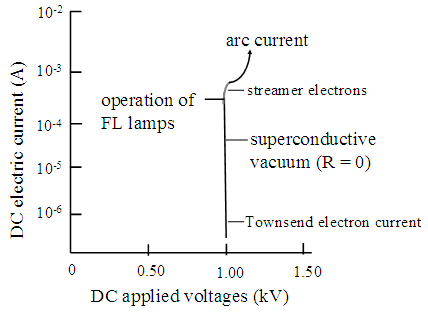
Figure 19. DC electric current between volume of glow lights on needle electrodes in vacuum-sealed glass tube that contains Ar atoms at pressure of 930 Pa (7 Torr)
The results in Figure 19 had already obtained by J. S. Townsend on 1903, but he could not analyze the curve as the superconductive vacuum. He gave the name as the Townsend electric current, as shown in Figure 19. The results shown in Figure 19 had used in the practical DC voltage regulation tubes before the development of the solid-state voltage regulation devices. The study on the voltage regulation tubes did not find the superconductive vacuum in the Ar gas space. They only paid their attention to the practical use of the devices. We have found that the FL lamps light up by the moving electrons in the superconductive vacuum between Ar atoms. Figure 20 illustrates the moving electrons in the superconductive vacuum in the lighted FL lamps.
Figure 20. Schematic illustration of superconductive vacuum for moving electrons in Ar gas space of lighted FL lamp with Ar gas pressure at 930 Pa (7 Torr)
The uniformly lighting of the Ar atoms in the FL lamps is limited by the electron flows in the vertical range in Figure 19. In the electric current at above 3 x 10⁻⁴ A, the electrons gather up to the electron beam in the Ar gas space. Finally, the electrons flow changes to the arc current, like as the thunder lightings. The practical FL lamps should be operated in the moving electrons below 3 x 10⁻⁴ A, corresponding to the 2.6 x 10¹⁵ electrons per second {= 3 x 10⁻⁴ Coulomb per second x (1.9 x 10⁻¹⁹ Coulomb)-1}. Thus, we have found the existence of the internal DC electric circuit between the volumes of the glow light at the both ends in the FL lamps. The formation mechanism of the internal DC electric circuit in the FL lamp is below:
The negative electric field inside of the volume of the glow light is completely neutralized by the presence of the large numbers of Ar1+. The weight of Ar1+ and Ar* is 1.7 x 10⁻²⁷ kg. The weight of electron is 9.1 x 10⁻³¹ kg. The moving particles in the volume of the glow light under the FDC are the electrons. Under the given FDC, the moving speed of the electrons in the neutralized volume of the glow light is the 104 times faster of the speed of Ar1+. The accelerated electrons in the volume of the glow light step out from the volume of the glow light and ionize the Ar atoms. The Ar gas space in the FL lamps is neutralized with the moving speed of the electrons of 108 m per second under the FDC. The needle cathode supplies the electrons into the volume of the glow light and the needle anode collects the electrons from the volume of the glow light. The external DC electric circuit consumes the electric power of WDC = 0.3 watt (1 x 103 V x 3 x 10-4 A). This conclusion is not our goal as the ideal FL lamps.

3.3. Reduction of External DC Electric Power Consumption of FL Lamps to WDC = 0

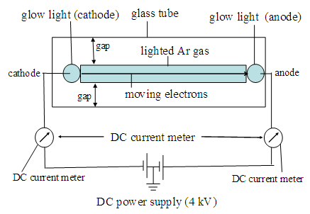
The volumes of the glow lights in Figure 16 are formed by the electric field from the needle electrodes, and are not by the electron flow from the needle electrodes. They are formed by the electric field from the needle electrodes. With a curiosity of the formation of the volume of the glow lights on the needle electrode, we made the flowing experiments. The surface of the needle electrodes are covered with the thin glass layer less than 10-4 m. The thin glass layer on the needle electrodes is the electric insulator. The thin glass layer on the needle electrode cut off the electron flow from the needle electrodes to the volume of the glow lights. Figure 21 illustrates the experimental configuration of the needle electrodes that are covered with the thin glass layers of around 1 x 10⁻⁴ m thickness. Fortunately, we obtain the volumes of the glow light on the thin glass layer on the both cathode and anode electrodes by the application of DC voltages above 1.0 kV. The results lead us to the following experiments.
Figure 21. Illustration of volume of glow light on thin glass layer on needle electrodes. Experiments are made with the DC voltage at 2 kV
The needle electrodes covered with the thin glass layer set in the FL lamp. The tested FL lamps do not have the phosphor screen. We have the same lighting results with the FL lamp, except for the zero DC current from the needle electrodes. The result in Figure 22 is the direct evidence that the lighting FL lamps are operated with the coexistence of the disparate external DC electric circuit and internal DC electric circuit [15]. The external DC driving circuit has no electric current. The tested FL lamp brilliantly lights up with the Ar*. The internal DC electric circuit is surely formed by the volumes of the glow lights without the electron flow from the needle metal electrodes. Accordingly, the electric power consumption of the external DC driving circuit is zero; WDC = 0. This is a moment that we have confirmed the new lighting mechanism of the FL lamps with the WDC = 0 of the external driving circuit.
We have found a distinguished advantage of the lighted FL lamps over other incandescent lamps with WDC = 0, without any sacrifice of the lighting conditions of the internal DC electric circuit. We like to know the more details of the lighting mechanisms in the Ar gas space between cathode and anode of the internal DC electric circuit in the FL lamps. However, we cannot directly detect the DC current between the cathode and anode of the internal DC driving circuit. The DC current between the cathode and anode in the internal DC driving circuit likes as the DC electric current shown in Figure 19. The DC current at above 4 x 10⁻⁴ A, the lighted FL lamps may have the arc current via the streamer beam current. The FL lamps are operated with the maximum DC current at 3 x 10⁻⁴ A.
Figure 22. Lighted FL lamp which cathode and anode are formed by volume of glow lights on thin glass layers on metal needle electrodes
The moving electron in the Ar gas space has the chance to meet the Ar atoms. The electron that meets with the Ar atom may receives the Coulomb’s repulsion from the electric field from the 3p6 orbital shell of Ar atom. Each Coulomb’s repulsion, the moving electron loses some amount of the kinetic energy. As the approaching electrons to the Ar atom have the kinetic energy higher than 15.7 eV, the Coulomb’s repulsion results in the ionization of Ar1+. The moving electron loses the kinetic energy of 15.7 eV by each Coulomb’s repulsion. As the moving electrons have attenuated the kinetic energies between 15.6 eV and 11.5 eV, the moving electrons may excite the Ar atoms (Ar*). The Ar* emits a photon within 10-6 sec after the excitation. As the moving electron has the kinetic energy smaller than 11.4 eV, the electrons recombine with the Ar1+ and the Ar1+ returns to Ar atoms. Thus, the lighted FL lamp reserves the Ar atoms in the operation, promising the operation life longer than 106 hours. We may calculate the statistical numbers of the Ar1+ and Ar* per second in the lighted FL lamp.

3.4. Calculations of Numbers of Ar1+ and Ar* (m3, s)-1 in Lighted FL Lamps

The scattered electron in the FDC > Forb meets other Ar atom and generates Ar1+. Figure 23 illustrates the moving electron in the superconductive vacuum with the ionization of two Ar atoms in the superconductive vacuum. The moving electron in the superconductive vacuum continuously meets the floating Ar atoms in the superconductive vacuum until the reduction of the kinetic energy to 15.7 eV for the excitation of Ar atom (Ar*). After the excitation of the Ar*, the moving electron recombines with the Ar1+, and Ar1+ returns to Ar atom.
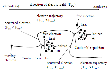
Figure 23. Schematic explanation of moving electron under electric field FDC and change of trajectory by Coulomb’s repulsion from two Ar atoms. Each Coulomb’s repulsion generates Ar1+ and free electron in Ar gas space
The moving electron in the superconductive vacuum continuously meets the floating Ar atoms in the superconductive vacuum until the kinetic energy to 15.7 eV for the excitation of Ar atom (Ar*). For the statistical calculation of the numbers of the Ar1+ and Ar* by one moving electron, we take the constant voltage at 1.0 kV as shown in Figure 19. The calculated numbers are 62 Ar1+ {= 1000 V x (16 V)-1} per one moving electron. After the generations of 62 Ar1+, the moving electron may excite one Ar*. After the excitation of the Ar*, the moving electron recombines with Ar1+, and Ar1+ returns to Ar atom. The moving of the specified electron from the cathode disappears from the Ar gas space. The average moving distance of the specified electron from the cathode is 6.2 x 10⁻⁵ m (= 62 x 10-6 m). The distance between the cathode and anode in the FL lamp is 1.0 m. Therefore, the specified electron from the cathode disappears before reaching to the anode in the FL lamp. The collected numbers of the electrons by the anode coincide with the emitted numbers of the electrons from the cathode. This means the numbers of the moving electron from the cathode never decrease and never increase in the Ar gas space. We must solve the puzzle in the constant numbers of the moving electrons in the lighted FL lamp.
By the referring to the results in Figures 23, it can statistically say that the same numbers (62) of the free electrons are also generated in the Ar gas space by the formation of Ar1+. The newly generated 62 electrons also move on in the superconductive vacuum under the FDC. The newly generated electrons instantly mix up with the original electrons under the FDC. If one pays his attention to the specified electron from the cathode, the specified electron surely disappears before reach to the anode. However, the electron from the cathode mixes up with the newly generated 62 free electrons in the Ar gas space. The ionization and excitation of the Ar atoms in the lighted FL lamps should be considered as the statistical results of the randomly mixed electrons from the cathode and generated free electrons in the Ar gas space. Therefore, we may take the moving electron from the cathode to the anode as the average of the statistical results of the moving electrons in the lighted FL lamps. As already calculated, the FL lamps (T-10) contain 1.4 x 10¹⁵ Ar atoms that correspond to 2 x 10¹⁸ Ar atoms per m3 of the volume of the Ar gas. Following calculations are made with the unit volume (m3) of the Ar gas. We consider the numbers of the electrons of 5 x 10¹⁵ electrons per second {= 3 x 10-4 A x 1.6 x 10-19 Coulomb} always presence between the cathode and the anode in the lighted FL lamps. The statistical calculations are given by the combinations of the numbers of Ar atoms and moving electrons.
Since Ar atoms randomly distribute in Ar gas space with the average separation distance of 1 x 10⁻⁶ m, the average numbers of the collisions of the moving electron in one direction are given by 1 x 10⁶ times {= (1 x 10⁻⁶ m)-1}. The numbers of the collisions in unit volume (m3) are given by 1 x 10¹⁸ per m3 {= (1 x 10⁶ m)3. Consequently, the numbers of the generated Ar1+ in the unit volume are calculated as 1 x 10¹⁸ Ar1+ (m3, s)-1. The numbers of the Ar* in the FL lamp are 1.6 x 10¹⁶ (m3, s)-1 {= 1 x 1018 x 62-1 (m3, s)-1}. The FL lamps do not use the Ar* as the lighting source. The origin of the lighting source is the excited Hg atoms (Hg*). The numbers of the Hg* is calculated from the numbers of Ar*.

3.5. Astronomical Quantum Efficiency of 1013 Visible Photons (m3, s)-1 in Lighted FL Lamp

The Ar gas pressure of the commercial HCFL lamp (T-10) is 930 Pa (7 Torr). The numbers of the Ar atoms at 930 Pa (7 Torr) are 2 x 10¹⁸ per m3. The pressure of the vaporized Hg atoms at 40oC is 0.67 Pa (5 x 10⁻³ Torr) that is 7 x 10⁻⁴ times of the Ar gas pressure {= 0.67 Pa x (930 Pa)-1}. The numbers of the vaporized Hg atoms in the HCFL lamp is calculated as 1.4 x 10¹⁵ Hg atoms (m3)-1 (= 2 x 10¹⁸ Ar atoms x 7 x 10⁻⁴). For the excitation of one Hg atom, the moving electron must have the 63 scatterings by the Coulomb’s repulsions before the excitation of the Hg atom. The calculated numbers of the Hg* in the Ar gas space at 40oC is 2 x 10¹³ Hg* (m3, s)-1 (= 1.4 x 1015 x 63-1).
The calculated 2 x10¹³ Hg* (m3, s)-1 are the quantum efficiency ηq of the Hg* by one moving electron in the lighted 40W-HCFL lamps. The total numbers of the Hg* in the FL lamps are given by the multiplication of the numbers of the moving electrons. The moving electrons in the internal DC electric circuit are 3 x 10⁻⁴ A that contain 2 x 10¹⁵ electrons per second {= 3 x 10-4 A x (1.6 x 10-19 Coulomb)-1}. Therefore, the numbers of the generated Hg* in the FL lamp are 4 x 1028 UV photons (m3, s)-1 (= 2 x 10¹³ Hg* x 2 x 10¹⁵ electrons per second). The calculated result can apply to the commercial HCFL lamps.
Now we calculate the numbers of the Hg* in the commercial 40W-HCFL lamp. Since the inner volume of the commercial 40W-HCFL lamp is 7 x 10⁻⁴ m3, the commercial 40W-HCFL lamp must emits 2.8 x 1025 UV photons per second {= 4 x 1028 (m3, s)-1 x 7 x 10-4 m3}. As described latter, the volume of the positive column is a half of the inner volume of the glass tube of the commercial 40W-HCFL lamps. The commercial 40W-HCFL lamps emit 1.4 x 1025 photons per second (= 2.8 x 1025 x 2-1). The phosphor screen on the inside wall of the FL lamps transduces the UV photons to the photons in the visible spectral wavelengths with the ηq ≈ 1.0. Therefore, each commercial 40W-HCFL lamp emits 1.4 x 1025 visible photons per second. Human eyes have adjusted for 5 million years to the daytime scenery under the slightly overcastting sky that is given by the around 1025 visible photons (m2, s)-1. The calculated results coincide with the illumination level by one commercial 40W-HCFL lamp. The commercial 40W-HCFL lamp already illuminates comfortably the 1 m2 room with the daytime scenery under the slightly overcastting sky. We have theoretically and experimentally proved the performance of the commercial 40W-HCFL lamps with the astronomical quantum efficiency ηq = 2 x 10¹³ visible photons per second. The remained subject is the reduction of the AC electric power consumption (WAC ≈ 80 watt) of the external AC driving circuit of the commercial 40W-HCFL lamps.

4. Development of Coil-EEFL Lamps as Most Advanced Incandescent Lamps

As described in previous section, the lighted FL lamps actually operate with the internal DC electric circuit that the cathode and anode are formed with the volumes of the glow light in the Ar gas. The volumes of the glow light are formed by the electric field from the needle electrodes of the external driving circuit, without the electron flow. The use of the needle electrodes in the practical FL lamps is not convenient. We must find out a simple way that forms the volumes of the glow light in the Ar gas space, rather than needle electrodes.

4.1. Coil-EEFL Lamps by Polarized Phosphor Particles

A candidate for the formation of the volume of the glow light in the Ar gas space is the polarized phosphor particles in the phosphor screen. The phosphor particles are polycrystalline particles in the sizes at around 5 x 10⁻⁶ m. Furthermore, the practical phosphor particles are the good piezoelectric crystals that easily deform the polarized particles under the electric field. We have carefully studied the details of the growths of the each phosphor particle in the heated crucibles [5]. By the control of (a) the temperature profile in the production furnace and (b) heating program of the crucibles in the furnace, we have the individual particles that are well crystallized polycrystalline particles [5]. Each polycrystalline particle contains many growing axes that make the sharp edge lines and points on the surfaces of the particles. The sharpness of the edge lines and points is less than 1 x 10⁻⁷ m. Figure 24 shows, as an example, the photograph of the developed phosphor particles under the scanning electron microscope (x 3000). The sharp edges and points on the surfaces of each polarized phosphor particles may work as the sharp points like as the needle electrodes.
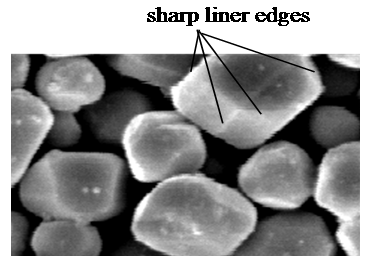
Figure 24. Photograph of phosphor particles under scanning electron microscope (x 3000)
With the expectation, the both ends of the outer glass wall of the FL lamp are covered with the lead wire (1 x 10⁻³ m diameter). The lead wire is covered with the plastic layer (~ 1 x 10⁻³ m thickness) to avoid the vacuum break by the arc discharge in the trapped air between coil metal and glass wall. Then, we have the coil external electrodes, coil-EE, on the outer glass wall of the FL lamp. As the negative DC voltage at 2 kV applies to the coil-EE at one side on the FL lamp, the phosphor screen under the EE lights up, indicating the formation of the volume of the glow light. Then, as the positive DC voltage applies to the coil-EE at other side, the phosphor screen under the coil-EE lights up. Then, the DC voltage at 2 kV applies to the coil-EEs at the both sides on the FL lamp. The coil-EEFL lamp brilliantly lights up under the external DC electric circuit with the applied voltages higher than 1 kV. Figure 25 shows the brilliantly lighted up the coil-EEFL lamp. The lighting mechanisms of the coil-EEFL lamps are the same with the volumes of the glow lights on the needle electrodes. We have confirmed that the sharp edges and points on the surface of the well-crystallized and polarized phosphor particles efficiently work as the needle electrodes for the generation of the volumes of the glow light in the Ar gas space of the FL lamps.
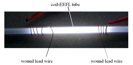
Figure 25. Photopicture of lighted coil-EEFL lamp under DC voltage at 2 kV
We have used the selected commercial CCFL lamps in the outer diameter 1 x 10⁻² m (T-4) for the experiments. Even though the external DC driving circuit of the coil-EEFL lamp has no electric current, WDC = 0, the converted coil-EEFL lamps light up with the higher illuminance (lm, m-2) than the original CCFL lamp. We have developed a prototype of the coil-EEFL lamp as the new lighting source with WDC = 0 in our hands. Since the power consumption of the external DC driving circuit is zero, we may use the piezoelectric transformer as the external DC electric source of the coil-EEFL lamps. The piezoelectric transformers can be operated with the electric power from the solar cells on the roof of the house.
The productions of the lighted coil-EEFL lamp require the advanced technologies of (a) the production of the phosphor particles (5), and (b) screening of the phosphor particles. The phosphor screen in the coil-EEFL lamps should be the thin as possible. Figure 26 (A) shows the cross-section of the ideal phosphor screen for the coil-EEFL lamp. If the coil-EEFL lamps are made with the thick phosphor screen as shown in Figure 26 (B), the coil-EEFL lamps have the dim light. The screen thickness is the important concern for the study on the coil-EEFL lamps. Therefore, the established screening technology of the phosphor screens never use to the production of the coil-EEFL lamps. The phosphor screens of the coil-EEFL lamps should be the same with the most advanced monitor CRTs in the high resolution [16].
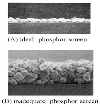
Figure 26. Cross-section of phosphor screen in coil-EEFL lamp (A) and in commercial HCFL lamp (B). Photograph are obtained with scanning electron microscope (x 1000)
Figure 27 illustrates the formation mechanisms of the volume of the glow light on the polarized phosphor particles in the lighted coil-EEFL lamp. The electric field from the EE on the outer glass wall polarizes only phosphor particles (white circles) in a few layers under the FEE. The FEE does not extend to horizontal direction in the phosphor screen. The volume of the glow light in the Ar gas only forms on the polarized phosphor particles. The depth of the volume of the glow light on the polarized phosphor screen is about 3 x 10⁻³ m that is the same size of the diameter of the volume of the glow light on the needle electrodes. The depth of the volume of the glow lights determines the optimized diameter of the coil-EEFL lamps within 1.0 x 10⁻² m {= (3 x 2 + 4) x 10-3 m}, although the coil-EEFL lamps light up with any diameters. Consequently, the coil-EEFL lamps wider than 1.3 x 10⁻² m (T-4) do not have the high illuminance (lm, m-2) from the phosphor screen. We must have the good understand for the production of the reliable coil-EEFL lamps.
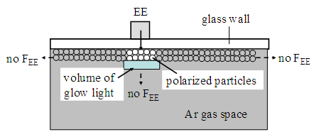
Figure 27. Illustration of polarized phosphor particles in screen by electric field from external electrode and formation of volume of glow lights as internal cathode (or anode) in Ar gas space
It has believed that in the Ar gas space, the lighted FL lamp has only the electric field FDC. We have found another electric field in the Ar gas space. That is the vertical electric field from the phosphor screens, Fphos, against to the horizontal FDC [5]. The positive column is formed in the Ar gas space where FDC > Fphos. The moving electrons in the positive column never step in the Ar gas space in the FDC < Fphos. The phosphor screens of the commercial HCFL lamps have the large Fphos. Naturally, the commercial HCFL lamps have the deep gap in 4 x 10⁻³ m between phosphor screen and positive column [17]. The performances of the commercial HCFL and CCFL lamps are seriously controlled by the deep gap of 4 x 10⁻³ m. For a better understanding of the operation properties of the FL lamps, we may explain the details of the deep gap that generates the limitation of the lighting of the FL lamps.
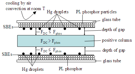
Figure 28. Schematic illustration of cross-section of FL lamp, partially. Electrons only move on in Ar gas space where FDC > Fphos. Commercial phosphor screen is heavily contaminated with insulators; generating deep gap of FDC< Fphos
Figure 28 schematically illustrates the formation of the positive column where FDC > Fphos in the Ar as space. Naturally, there is the deep gap between the positive column and phosphor screen in the established FL lamps. The existence of the deep gaps in the lighted FL lamps has overlooked in the past study. The depths of the gap are determined by the FDC < Fphos. The depth of the gap of the commercial 40W-HCFL lamps is around 4 x 10⁻³ m. Therefore, the diameter of the positive column in the 40W-HCFL lamp (T-10) is 2.2 x 10⁻² m {= (3.0 – 0.8) x 10-2}. If you consider the inner diameters of the FL lamp and diameter of the positive column, the difference looks like a small. However, when you consider the volumes of total Ar gas (VAr) and the volume of the positive column (Vposi), you may find the serious problems with the depths of the gap on the performances of the lighted FL lamps. The VAr and Vposi in the FL lamp are calculated by (πr2l) where r is the radius of the inner diameter of the FL lamp and positive column respectively.
We have calculated the ratios of the (Vposi /VAr) as a function of the outer diameters of the FL lamps with l = 1.0 m long. The parameters are the depths of the gaps; e.g., 0.1, 0.3, 1.0, 2.0, 3.0 and 4.0 (x 10-3 m), respectively. Figure 29 shows the calculated results. The results are solely determined by the Fphos that does not changed with the Ar gas pressures. At glance of Figure 29, the Vposi of the commercial HCFL lamps in the outer diameter of 3.2 x 10⁻² m (T-10) is only 60% of the VAr. The moving electrons involve in only 60% of the Ar gas space. Other 40% of the Ar gas is in the gap. The moving electrons never step in the gap. The coil-EEFL lamps must produce with the (Vposi /VAr) larger than 0.9, that is obtain with the narrow gap between phosphor screen and positive column. The favorable coil-EEFL lamps are produced with the depth of the gap shallower than 4 x 10⁻⁴ m as possible. We cannot directly determine the Fphos. The study on the Fphos can be made by the measurements of the CL intensities as a function of the applied voltages on the phosphor screen that is the voltage dependence (VD) curves of CL.
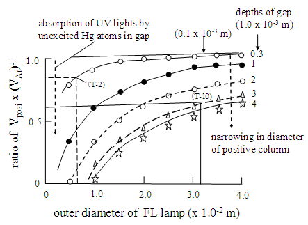
Figure 29. Curves of (Vposi x VAr-1) of FL lamps as a function of outer diameters of FL lamps. Parameter is depth of gap in FL lamps
Figure 30 shows VD curves of the low voltage CL phosphor screen in 3 x 10⁻⁶ g per 10-4 m2 (= 3 mg per cm2) and PL phosphor screen in any screening density. The VD curves of the low voltage CL phosphor screens in 3 mg per cm2 have the threshold voltage at 110 V. The threshold voltages of the low voltage CL phosphor screens sensitively shift to the high voltage with the screen thickness as shown in Figure 30. The VD curve of the thick screens approaches to the VD curve of the PL phosphor screen. The threshold voltage of the VD curves of the PL phosphor screen is 2,000 V that does not change with the screen thickness and by the surface contaminations on the phosphor particles. This is because the threshold voltage is determined by the surface-bounded-electrons (SBE) on the phosphor particles [5].
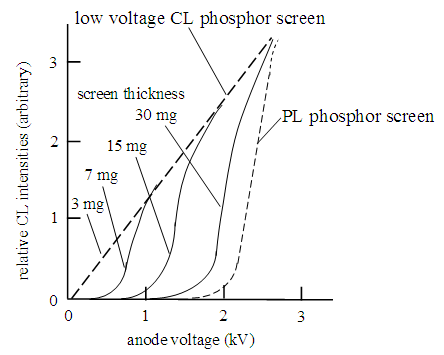
Figure 30. Voltage dependence curves of low voltage CL phosphor screen and PL phosphor screen. Low voltage dependence curves change with thickness of phosphor particles in screen
Now it is clear that if the phosphor screen in the coil-EEFL lamps in the diameter narrower than 1.5 x 10⁻² m is made with the commercial PL phosphor powders for the HCFL lamps, the produced coil-EEFL lamps do not emit the light. Because the PL phosphor powders for the commercial HCFL lamps are made with the surface treatments that generate the strong FSBC on the phosphor particles. The approaching electrons to the phosphor screen receive the strong Coulomb’s repulsion from Fphos. The repulsed electrons only move on in the Ar gas space in which FDC > Fphos.
We must know the negative factor of the Ar atoms in the gap. The negative factor is for the illuminance (lm, m-2) of the lighted FL lamps. The heat conductance of the Ar atoms at 1 atmosphere is 3.9 x 10⁻⁵ cal (deg, sec, at 0°C). The Ar gas at 930 Pa (7 Torr) is 3.9 x 10⁻⁷ cal (deg, sec, deg) that is good thermal insulator. The heat source in the lighted FL lamp is only ionization of the Ar atoms in the positive column. Therefore, the Ar gas in the gap does not involve in the generation of the heat in the lighted FL lamps. The positive column is thermally insulated by the Ar gas in the gap. The Ar gas in the positive column in the commercial 40W-HCFL lamp heats up to around 40°C that can be detected by the infrared thermometer. The origin of the light in the lighted FL lamp is the UV lights from the excited Hg* in the positive column. The numbers of the evaporated Hg atoms in the positive column is not simply determined by the temperature of the positive column. The Hg droplets are on the phosphor screen. As shown in Figure 28, the Hg droplets on the phosphor screen only heat up from the heated positive column. We cannot expect the heat conductance and thermal convection of the Ar gas in the gap. The Hg droplets on the phosphor screen only heat up by the thermal radiation from the positive column. The Hg droplets slowly heat up to the equilibrium temperature. Consequently, the light intensities of the FL lamps slowly increase after turn-on of the electric power of the external driving circuit, giving rise to the build-up curve of the light intensity as a function of the lighting times. The detected build-up curve is fast with the shallow gap and is a very slow with the deep gap of the FL lamps. The saturation levels of the build-up curves also differ with the depths of the gap. We may use the build-up curves of the produced FL lamps as the qualitative determination of the depths of the gap in the lighted FL lamps.
Figure 31 shows two build-up curves of the FL lamps with the ratios of (Vposi x VAr-1) = 0.9 and 0.6, respectively. The results of the build-up curves clearly inform us the remarkably change with the depth of the gaps. The (Vposi x VAr-1) = 0.9 has the 3 x 10⁻⁴ m depth of the gap, and (Vposi x VAr-1) = 0.6 has the 4 x 10⁻³ m depth. The commercial 40-HCFL lamps have the build-up curve of (Vposi x VAr-1) = 0.6. The result in Figure 31 indicates that the illuminance (lm, m-2) of the commercial HCFL lamps may improve more than 30% by the change to the (Vposi x VAr-1) = 0.9. The improvement is only made with the special arrangement of the phosphor particles of the clean surface chemically and physically. The phosphor particles distribute in the narrow particle sizes with the log-normal distribution [17].
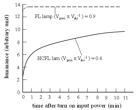
Figure 31. Build-up curves of light of FL lamp having (Vposi x VAr-1) = 0.8 and Commercial HCFL lamp that has (Vposi x VAr-1) = 0.6
As illustrated in Figure 28, the Hg droplets in the unlighted FL lamps are on the phosphor screen. The heat source is the positive column. The Hg droplets on the phosphor screen heat up by neither heat conductance nor thermal circulation of the heated Ar gas. The Hg droplets on the phosphor screen are only heated by the thermal radiation from the positive column. Here arises a serious problem. The outer glass wall of the FL lamps is cooled by the thermal convection of the cool air at the room temperature (22°C). The equilibrium temperature at the outer glass wall of the lighted HCFL lamps is below 30°C. The temperature of the Hg droplets on the phosphor screen determines the evaporation of the Hg atoms in the lighted FL lamps.
Another negative factor of the Ar gas in the gap is the optical absorption of the UV lights from the positive column before reach to the phosphor screen. Origins of the lights of the FL lamps are the UV lights at 254 nm and 185 nm from excited Hg*. The UV lights are respectively assigned as the electron transitions between excited 3p1 and 1p1 to the grand state 6s0 respectively. Therefore, the unexcited Hg atoms in the gap efficiently absorb the UV lights from the positive column before reaching to the phosphor screen.
We may quantitatively calculate the improvement of the illuminance (lm, m-2) of the commercial 40W-HCFL lamps. The unexcited Hg atoms in the 40% Ar gas in the gap absorb the UV lights from the positive column, so that the gap absorbs 24% (0.6 x 0.4 = 0.24.) of the emitted UV lights in the positive column. The UV lights that penetrate through the gap corresponds to 36% (= 60% - 24%) of the evaporated Hg atoms in the Ar gas space in the lighted HCFL lamp. The phosphor screen transduces the UV lights to the visible lights. If the commercial HCFL lamps are produced by the advanced phosphor powders [17], the light output from the HCFL lamps will go up to more than double (e.g. 72%). However, the numbers of the Ar1+ (forming CAr) in the positive column also increase. The electrodes of the external AC driving circuit pick up the double of the AC induced current from the CAr. So far as the HCFL lamps are operated with the external AC driving circuit, the reduction of the depth of the gap is not the attractive subject. On the contrary, the coil-EEFL lamps are operated with the external DC electric circuit with the WDC = 0. Therefore, the reduction of the depth of the gap is an attractive subject of the coil-EEFL lamps.
For the preparation of the coil-EEFL lamps, you must control of (1) the thickness of the phosphor screen with a few layers as shown Figure 26 (A). (2) The production furnace of the coil-EEFL lamps should have the uniform temperature profile. Because the glass tubes are a good thermal insulator, the heaters in the furnace should be covered with the heat scatters for the uniformity of the temperature profile of the heated FL glass tubes in the furnace. (3) You cannot use the established pumping facilities of the commercial HCFL lamps for the production of the coil-EEFL lamps. The inside of the vacuum systems of the production of the HCFL and CCFL lamps is heavily contaminated with the oil-vapor of the vacuum pumps. Never use of the established pumping system of the HCFL lamps for the production of the coil-EEFL lamps.

4.2. Lighted coil-EEFL Lamps Set in Vacuum-Sealed Sheath Tube

The coil-EEFL lamps must have the very shallow gap between positive column and phosphor screen; hopefully less than 1 x 10⁻⁴ m. We have obtained 10 CCFL lamps in the outer diameter 3 x 10⁻³ m from a FL store. The CCFL lamps of the Ar gas pressures at 6.7 x 10³ Pa (= 50 Torr) have the 3 x 10⁻⁴ m depth of the gap. The 10 CCFL lamps convert to the coil-EEFL lamps. Following experiments are made with the converted coil-EEFL lamps. The power consumption of 10 coil-EEFL lamps in parallel connection is zero, WDC =0. The coil-EEFL lamps are operated with the external DC driving circuit with 3 kV. Individual coil-EEFL lamps lights up with the illuminance (1200 lm, m-2) with the WDC = 0. The illuminance is determined the Ulbricht Sphere in which is incorrectly modified by the reflection plate [18]. Therefore, the determined illuminance is the relative illuminance. The bottom line in Figure 32 shows the results. Then, the EEs of the 10 coil-EEFL lamps are arranged with the parallel connection in the room. The illuminance of the coil-EEFL lamps in air does not linearly increase with the numbers of the parallel connections as shown in Figure 32. The outer glass wall of the coil-EEFL lamps are cooled with the thermal convention of the cool air in the room. When the coil-EEFL lamps set in the vacuum-shield sheath tube, the illuminance of the coil-EEFL lamps linearly increases with the numbers of the parallel connection of the coil-EEFL lamps as shown in Figure 32. The vacuum pressure of the vacuum-shield sheath tube is 600 Pa (= ~ 5 Torr). The vacuum sealed containers should be opaque for the practical use for the generation of the shadow less images.
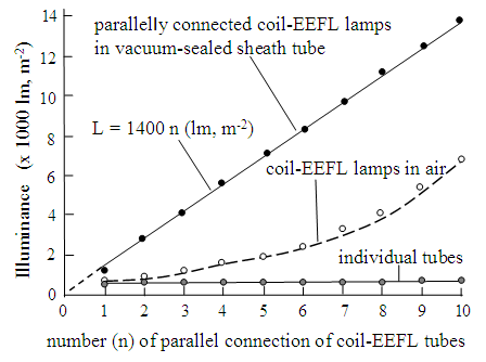
Figure 32. Illuminance (lm, m-2) curves of individual coil-EEFL lamps, coil-EEFL lamps with parallel in air, and coil-EEFL lamps in parallel connection in vacuum-sealed sheath tube
The results in Figure 32 definitely inform us that the coil-EEFL lamps should be operated with the parallel connection of the required numbers for the illumination purpose of the rooms and offices. The coil-EEFL lamps in the parallel connection set in the vacuum-sealed and optically opaque container. With this way, the coil-EEFL lamps brilliantly and comfortably illuminate the shadow less images in the rooms of the house and offices in buildings. Because the electric power consumption of the adequate numbers of the coil-EEFL lamps is WDC = 0, the coil-EEFL lamps in the parallel connection may operate with the electric power supply of the combination of the solar cells and the electric battery in each home, and office in the buildings. Then, the distribution power networks from the electric power generators to home and buildings will disappear on the ground. The electric power consumption on the world for the light source may reduce to nearly zero. The pollution level in air from the electric power generators on the world may reduces to the target level (more than 31 %) of the Paris Agreement of the United Nation on 2016.

5. Conclusions

We have studied the established incandescent lamps from the basics that are the arrangements of the atoms in the vacuum. The electrons move on in the bounding shell of the metal. Naturally, moving electrons have the electric resistance caused by the thermal perturbation from the neighbor atoms. The W-filament lamps use the heated metal at the high temperatures by the Joule Heat. The LED lamps use the moving electrons in the vacuum between atoms at lattice sites. The lights from the LED lamps are generated by the recombinations of the injected electrons and holes in the luminescence centers, giving rise to the ηq less than 1.0. Furthermore, the injected electrons that move on in the narrow vacuum between atoms at the lattice sites inevitably have the electric resistance caused by the thermal perturbation from atoms at lattice sites. As the illumination source, the LED lamps must inject, at least, 1025 electrons (m2, s)-1 for the illumination purpose. The injection of the large numbers of the electrons to the LED lamps generates the very high temperatures by Joule Heat. The stability of the luminescence centers in the junction of the LED lamps requires the operation temperature below 70°C. On the other hand, the FL lamps use moving electrons in the superconductive vacuum between Ar atoms that float in the vacuum, (not at the lattice sites) resulting in the astronomical quantum efficiency of ηq = 1013 visible photons (m3, s)-1.
The superiority of the FL lamps has obscured in the study for nearly 90 years with (i) the wrong assignments of the vacuum between Ar atoms, (ii) incorrect determination of the electric power consumption, Wact, of the external AC driving circuit, (iii) the coexistence of the disparate external driving circuit and internal DC electric circuit in the operation of the FL lamps, (iv) hypotheses of the electron sources, (v) ignorance of superconductive vacuum in the Ar gas, (vi) miscalculation of the generation energy of the lights, (vii) lighting mechanisms of the Hg atoms in the Ar gas, (viii) unknown of the existence of the capacitor, CAr, in the lighted FL lamps, and (ix) unknown of the vertical electric filed Fphos from the contaminated phosphor screens. After the clarification of all of them, we have developed a prototype of the coil-EEFL lamps that are operated with external DC driving circuit with WDC = 0.
The cathode and anode of the internal DC electric circuit in the FL lamps are formed in the Ar gas space with the volume of the glow lights on the needle electrodes. The volume of the glow lights as the cathode and anode are also formed under the electric field from the external electrodes (EE) on the outer glass wall of the FL lamps. The phosphor particles on the inner glass wall of the FL lamps form the volume of the glow lights by the electric field from the EE. The results lead us to the development of the coil-EEFL lamp. The electrons from the cathode move on in the superconductive vacuum to the anode of the internal DC electric circuit. The moving electron in the superconductive vacuum gives the astronomical quantum efficiency ηq = 2 x 10¹³ photons (m3, s)-1. The maximum electron current between the cathode and anode of the internal DC electric circuit is 3 x 10⁻⁴ A, corresponding to the numbers of 1015 electrons. The generated photons from the coil-EEFL lamps are 1028 visible photons (m3, s)-1. The fundamental mechanisms of the coil-EEFL lamps have studied in this report for the production of the coil-EEFL lamps by someone else. The author is 85 years old with the cancer. He hopes someone continue this project for the contribution to Green Energy Project by UN in a near future. If someone needs his help, he may help you in the left of his life.

ACKNOWLEDGEMENTS

The author wishes to express his great appreciation to Mr. Nobuyoshi Ohtani and Dr. Takao Toryu for their instruction and chance to early study on the characteristic properties of the phosphor powders from the basics with the hand-made instruments in the small laboratory modified from the green house in Chigasaki, Japan before 1953. They also instructed the author that the results of the study are for human society rather than personal benefit. Since then, the author has continued his study on the materials by the hand-made instruments for the development of the new products on his life for the society.

Appendixes

In early study on the FL lamps, the neon tubes had studied as the lighting lamp. Because the Ne atoms release a small amount of the heat by the ionization of small number of the Ne atoms, the FL tube with Ne gas did not absorb the attention as the illumination source. We have found that the volumes of the glow light by the Ne atoms are also formed by the electric field from the EEs on the outer glass tube. We may have the cathode and anode of the internal DC electric power generator in the Ne gas space. We also know that the Xe atoms are in gas phase. So the heating Xe toms in the FL lamps are unnecessary in the operation of the coil-EEFL lamps. Xe atoms also emit the UV light at 172 nm and 142 nm in the vacuum ultraviolet lights. The adequate phosphor screen may transduce the vacuum UV lights to the lights in the visible spectral wavelengths. The coil-EEFL lamps may produce with the combination of Ne and Xe gases, without Hg droplets. The gas pressure of Ne atoms is around 103 Pa (~ 7 Torr) and the gas pressure of Xe atoms is around 2 Pa (~ 10-2 Torr).
The melting temperature of Xe is -112°C, and boiling temperature is -107°C. Xe at room temperature is always gas phase. The lighted FL lamps do not require the heat for the Xe atoms. The emitted UV lights from the excited Xe* are at 172 nm and 142 nm in the vacuum UV range. The preferable phosphor screens for the FL lamps by the mixture of Ne and Xe gases are (a) BaMgAl10O17:Eu as the blue light, (b) Zn2SiO4:Mn as the green light, and (c) Y2O2S:Eu as the red light. The plasma display panel (PDP) uses (Y, Ga)BO3:Eu phosphor as the red lights. However, the control of the sizes and surface conditions of the (Y, Ga)BO3:Eu phosphor is a very hard. We recommend the use of the Y2O2S:Eu red phosphor powder that each phosphor particle has the sharp points and sharp edges [5]. Furthermore, sulfur in the Y2O2S:Eu red phosphor does not have the chemical reaction with Xe atoms. The study on the coil-EEFL lamps by the combination of Ne and Xe gases is underway.

References

[1]  Lyuji Ozawa [Contribution to Paris Agreement of United Nation by coil-EEFL lamps with zero electric power consumption], International J. of Materials Science and Applications, 6, pp 65-76, 2017, published online, http://www.sciencepublishinggroup.com/j/sr.
[2]  Lyuji Ozawa, [coil-EEFL tube as supreme incandescent light source with zero electric power consumption, astronomical quantum efficiency, and long life], Global Journal of Science Frontier Research: A, Physics and Space Science, 15, pp 16-50, 2015, http://creativecommons.org/licensed/by-nc/3.0/.
[3]  Y. Narukawa, M. Ishikawa, D. Sugaya, M. Sano, and T. Mukai, Appl. Phys. 43, p 3540, 2010.
[4]  Lyuji Ozawa and Yakui Tian, [Restriction of Solid Lighting Source in Practical Use], J. China Ill. Engs., Soc., 6, pp57-64, 2011.
[5]  Lyuji Ozawa [Cathodoluminescence and photoluminescence], CRC Press, Taylor & Francis Group, Boca Raton, London, New York, 2007.
[6]  Y. Yamanaka, J. Narita, T. Sakamoto, H. Narimatsu, M. Sano, and T. Mukai, Phys. Stat. Sol., 204 p 2087, 2007.
[7]  F. Mayer, US Pat. 2,182,732 (1928).
[8]  Handbook of [Electric Discharge Lamps], Japanese Institute of Electric Engineers, (1973), and Handbooks in other countries.
[9]  Phosphor Handbook, Second Edition by William Yen, ISBN; 0849335647, CRC Press, Taylor & Francis Group.
[10]  J. F. Waymouth, [Electron Discharge Lamp], MIT Press, 1971.
[11]  American Vacuum society Classics, (1) The fundamental data on electrical discharge gases, (2) Field emission and field ionization, (3) Vacuum technology and space simulation, (4) The physical basics of ultrahigh vacuum, (5) Handbook of electron tube and vacuum techniques, (6) Vacuum sealing techniques, and (7) Ionized gases, American Institute of Physics, 1993.
[12]  Lyuji Ozawa, [Formation and life curves of oxide cathodes], Display and Imaging, 4, pp 59-72, 1996, in Japanese.
[13]  Lyuji Ozawa and Tian Yakui, [A breakthrough in the study on FL tubes], J. Chinese Ill. Soc., 8, pp 86-94, 2013.
[14]  Lyuji Ozawa and Yakui Tian, [A new 4G electron source for FL tubes], J. Chinese Ill. Soc., 7, pp 58-65, 2012.
[15]  Lyuji Ozawa and Yakui Tian, [Coexistence of disparities of external AC driving circuit and internal DC electric circuit in operation of FL tube], J. China Ill. Engs. Soc., 6, pp 18-30, 2011.
[16]  Lyuji Ozawa, [Ideal distribution of polycrystalline phosphor particles for application to phosphor screens in CRT], International Journal of Material Science and Applications, 6, pp 6-17, 2017, published online, (http://www.sciencepublishinggroup.com/j/ijmsa).
[17]  Lyuji Ozawa, [Special arrangement of phosphor particles in screen for optimization of illuminance (lm m-2) of FL tubes], Science Research, 3, pp261-272, 2015, published online, (http://www.sciencepublishinggroup.com/j/sr.
[18]  Lyuji Ozawa, [Illuminance (lm m-2) of compact 20W-HCFL tube], Science Research, 3(4), pp 170-179, (http://www.sciencepublishinggroup.com/j/sr.