-
Paper Information
- Next Paper
- Previous Paper
- Paper Submission
-
Journal Information
- About This Journal
- Editorial Board
- Current Issue
- Archive
- Author Guidelines
- Contact Us
International Journal of Energy Engineering
p-ISSN: 2163-1891 e-ISSN: 2163-1905
2017; 7(3): 74-78
doi:10.5923/j.ijee.20170703.02

Study of Solar Reactor Storage Systems Based on Phase Transition Material
 Abstract
 Reference
 Full-Text PDF
 Full-text HTML
F. F. Mammadov
Azerbaijan State Oil and Industry University, Baku, Azerbaijan
Correspondence to: F. F. Mammadov, Azerbaijan State Oil and Industry University, Baku, Azerbaijan.
| Email: |  |
Copyright © 2017 Scientific & Academic Publishing. All Rights Reserved.
This work is licensed under the Creative Commons Attribution International License (CC BY).
http://creativecommons.org/licenses/by/4.0/

In the paper different phase transition materials have been tested. Various heat storage processes were studied in the solar heat-energy system. Due to the experiments done in the universal solar reactor thermal efficiency, heat and energy parameters and existing thermal losses were determined.
Keywords: Solar heat energy systems, Phase change material, Solar reactor, Heat energy parameters, Heat accumulator
Cite this paper: F. F. Mammadov, Study of Solar Reactor Storage Systems Based on Phase Transition Material, International Journal of Energy Engineering, Vol. 7 No. 3, 2017, pp. 74-78. doi: 10.5923/j.ijee.20170703.02.
Article Outline
1. Introduction
- Heat accumulation for solar energy systems is always actual question. At present heat accumulation is being realized in the solar energy systems by using different ways and methods [1, 2]. Several methods are applied in the solar energy-engineering stations possesing the greatest power. While choosing the heat-retaining materials, thermal-physical properties’ alternation in the rage of the highest temperature and presssure of these materials should be studied beforehand. heat-storage materials must be rocks and pebbles for accumulating hot air [3] and heating liquids having the highest thermal capacity used as the heat-transfer material materials [4]. Now during the experiments the heat storage materials with persistent features have been to be utilized for whole day, no depending on solar rays’ density and environmental temperature in any time of the day to get hot water and steam for several technological processes. In the experiments carried out before [5-7] the heat accumulating materials possessing several phase changing were applied. According to these experiments I dare say that in all time teh volume filled with heat storage material can contact through heat-exchanging aparratus to the slar energy device. This causes the additional heat and electric energy losses. In the picture the deffects appearing during heat staroge and gradual heat have been shown. Ÿ Long –term heat storage on the stable temperature and the technological processes is getting to be difficult;Ÿ Additional energy is demanded for heat accumulating materials action on the double circuit system;Ÿ Volume and weight are greater in the heat storage materials.In order to solve such problems firstly, the laboratory plant of solar heat exchanging solar reactor accumulation system have been developed. The general view of the experimental plant was given in figure 1.
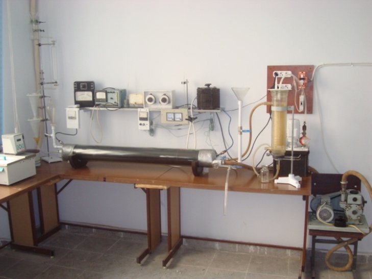 | Figure 1. General view of solar heat-exchanging – solar reactor accumulating system in laboratory condition |
|
2. Estimation of Thermal Efficiency of the Construction
- On the principal scheme given in the reference [9] in the solar heat exchanging – solar reactor accumulation system in order to define the dependence for some technlogical parameters change have been studied during the experiments. Usage the water and air heated within unit time in the stationary regime accordingly kg/hour; m3/hour and speed m/sec have been measured. To control the temperature of the heat accumulating material inside of the device one laboratory auto transformer and two thermal-supplier have been used. The results obtained due to the direct and per contra current of the water and air heated at several temperatures in the inside pipe of the heat exchanger have been noted to the technlogical scheme. By this purpose, in the experimental device onto the inside pipe air current regime has been studied: here all experiments have been done due to the 1;1,5;2m/sec air speed, 20
 200°C temperature intervals were realized. Each temperature step was after 20°C all experiments have been realized in the stationary condition. Minimal experiment duration consists of 6,8,10, and maximal one covers 24 hours. Liquid current speed range is less and therefore gravitation regime having laminar viscosity is observed here the thermal coefficient
 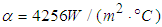 is. Due to this the length of the pipe inside
  the device and external
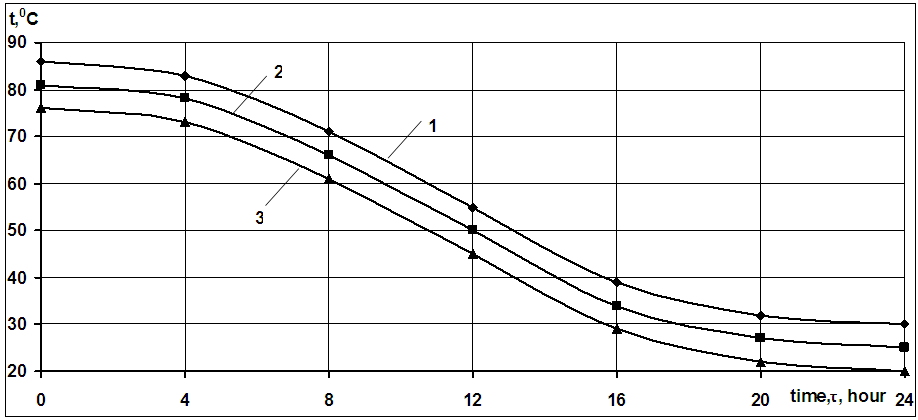
  wall temperature were measured. As shown from figure 2 system is heated maximally till 200°C. After having got stationary regime air current having 3 several speeds act through inside pipe. Gradually cooling dynamics of the system happens. During supplying the air current through the inside pipe the demanded time and the stationary work regime moment were defined.
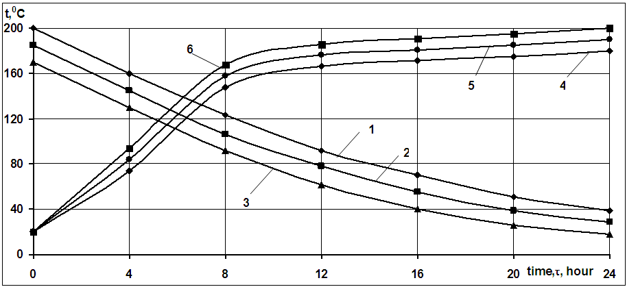 | Figure 2. Changing Dynamics of temperature depending on the time in the heat storage system Here, accordingly 1,2,3 curves for dependence of cooling system on the time at air current 1;1,5;2m/sec speed; accordingly 4,5,6 curves for dependence of stationary regime of the device on the time at 1;1,5;2m/sec air current speed |
 | Figure 3. Accordingly, 1,2,3 curves for time dependence of the hot air stream heated through the inside pipe wall at 1;1,5;2m/sec air current speed |
 | Figure 4. Accordingly, 1,2,3 curves for dependence of device isolation surface temperature changing on time at 1;1,5;2m/sec air current speed |
3. Thermal-Energy System Calculation
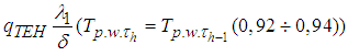
- In the thermal-energy system calculation the main problem is the heat amount determination [10] which comes through heat storage material to the inside pipe and to the medium heated. For this heat distribution through heat storage material to the inside pipe should be calculated according to the following formula [11]:
 Here,
Here,  - pipe wall surface temperature during heating (latest)
  , °C;
, °C; - during
  heating temperature (begin) of pipe wall surface, °C;
 - cooling rate of the heat storage material in the system,
 - heat transfer coefficient being heated through pipe wall,
 - square of the internal pipe surface, m2;
 of the pipes in the heat accumulating device, in this case
 - heat capacity of heat storage material,
 - density of the heat storage material, kg/m3;
 - volume of heat storage material, m3;
 - heat transition coefficient of the heat storage material,
 - half volume width where heat storage material is in,
 and
and  - accordingly cooling and heating duration,
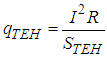 - heat current amount departed from thermoelectric heater (TEH) surface, W/m2;
 - electricity current intensity of TEH, A;
 - resistance of TEH, Om;
 - surface square TEH, m2;
 - total heat amount generated in the heat storage system in which total heat loss aren’t meant. Thus, efficiency in the system changes between
  . Accumulation ability
 of the heat storage material existing in the heat accumulating system is to be calculated due to the next formula:
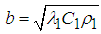 The selected phase transition material’s accumulation ability gives opportunity the system to work effectively on the demanded temperatures.
 4. Determination of Heat Losses
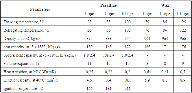
- In order to define the losses happening in the solar heat exchanging and solar reactor accumulation system the proper method has been selected [12-14]. For this the heat losses in the heat storage system have to be determined:
 Here,
Here,  - temperature in the accumulation system, °C;
 - environmental air temperature, °C;
 - weight of the phase transition accumulating material,
 - specific thermal volume of the phase transition accumulating material,
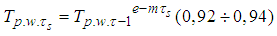
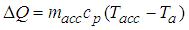
  Though the isolation cover on the solar heat exchanger – solar reactor accumulating system, there is heat loss. Especially the heat loss happens by the convective way, so the heat loss on solar reactor surface to the environment should be determined like this:
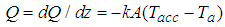 Here,
Here,  - heat transfer coefficient,
 square where heat is departed,
 If the both equations are to be joined then:
 In order to calculate efficiency of such systems the specific situation is to be taken into consideration. Firstly system has to be developed to the suitable technological process which is known beforehand. This may for two conditions: the first is for the technological process with the highest temperature, the second for the technological process with the lowest temperature.
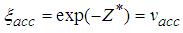
 here,
here,  - unmeasured time;
 - efficiency of the accumulation systemAccording to the analysis of the carried out calculations and experiments I dare say that energy economy and ecological clean technological supply have great advantage. Heat accumulation in the alternative energy devices for long time and apply in the technological processes in different industry fields is actual and can be solved by this way.
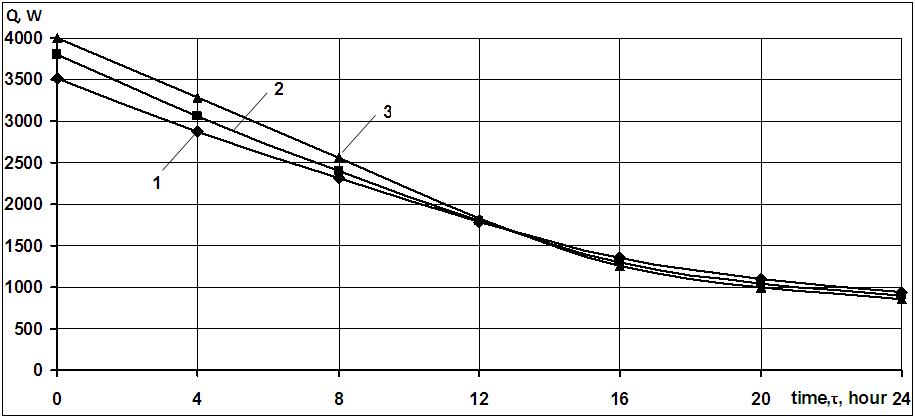
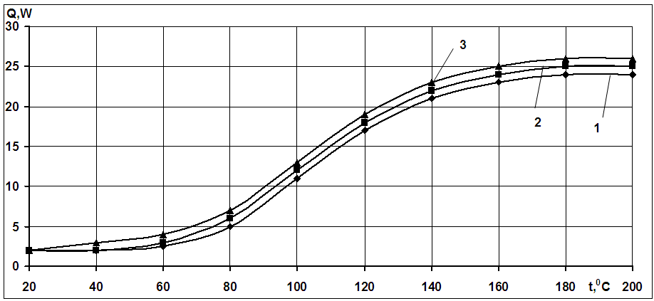 | Figure 5. Dependence of the heat losses on the time in the general system. Accordingly, 1,2,3 curves for air current 1;1,5;2m/sec speed |
5. Conclusions
- Due to the experiments realized in current solar heat-exchanging reactor I dare say that heat can be stably accumulated for a long time to the phase transition material. The device may be used as the parabolic trough concentrator reactor. Aplication of the device is advisable in cloudy and half-cloudy weather conditions. Such kind of system is utilized to obtain abd accumulate hot liqiud and vapor for the process. The device has the long-term and reliable work ability.