-
Paper Information
- Paper Submission
-
Journal Information
- About This Journal
- Editorial Board
- Current Issue
- Archive
- Author Guidelines
- Contact Us
International Journal of Energy Engineering
p-ISSN: 2163-1891 e-ISSN: 2163-1905
2017; 7(2): 39-50
doi:10.5923/j.ijee.20170702.01

Fabrication and Characterization of Reflectors by Physical Vapour Deposition of Nanoscale Thin Films of Ag and Cu for Concentrated Solar Thermal Power Applications
 Abstract
 Reference
 Full-Text PDF
 Full-text HTML
Christian N. Nwosu, Michael U. Onuu
Department of Physics/Geology/Geophysics, Faculty of Science, Federal University, Ndufu-Alike, Ikwo, Nigeria
Correspondence to: Michael U. Onuu, Department of Physics/Geology/Geophysics, Faculty of Science, Federal University, Ndufu-Alike, Ikwo, Nigeria.
| Email: |  |
Copyright © 2017 Scientific & Academic Publishing. All Rights Reserved.
This work is licensed under the Creative Commons Attribution International License (CC BY).
http://creativecommons.org/licenses/by/4.0/

The Ag and Cu thin films were deposited using physical vapour deposition (PVD) technique which is a novel surface engineering method. Ag thin film of 100nm was deposited by thermal evaporation onto a thin microscopic glass substrate while the Cu thin film (50nm) was deposited on the Ag surface via sputtering. The deposited thin films were finally backed with 54µm Pb based paint by means of a mechanical process with a hand coater. The reflectors showed no sign of degradation after one week exposure to air prior to paint backing. The reflectors so fabricated were characterized for compositional, structural, morphological and optical properties using scanning electron microscopy (SEM), energy dispersive (X-ray) spectroscopy (EDS) and optical spectroscopy. The observed reflectance from the spectroscopy analysis showed high reflectance of 98 – 99% at wavelength band of 400 nm – 700 nm which is ideal for concentrated solar (thermal) power (CSP) applications.
Keywords: Physical vapour deposition, Concentrated solar thermal power, Thin film and nanoscale coating
Cite this paper: Christian N. Nwosu, Michael U. Onuu, Fabrication and Characterization of Reflectors by Physical Vapour Deposition of Nanoscale Thin Films of Ag and Cu for Concentrated Solar Thermal Power Applications, International Journal of Energy Engineering, Vol. 7 No. 2, 2017, pp. 39-50. doi: 10.5923/j.ijee.20170702.01.
Article Outline
1. Introduction
- Reflectors are one of the most important components of a concentrated solar (thermal) power (CSP) technology. The manufacturing of this CSP component is currently a great challenge facing the technology because developing a CSP reflector with high reflectivity and uniform coatings remains an upheaval task in the industry. Achieving an ideal CSP reflector will help to ensure that CSP as a source of power becomes sustainable; this is because with such reflectors, the current high cost of electricity from CSP will be drastically reduced. This is so because such reflectors can withstand the adverse environmental conditions and, at the same time, achieve high reflectance of about 100% (Bhattacharya et al., 2012; Hatwaambo et al., 2009).CSP is one of the emerging solar energy technologies. Its applications range from electricity generation, solar cooking, industrial heating, solar drying, solar ponds, solar chimney, solar air-conditioning and solar chemical synthesis (Fernández-García et al., 2010; Thirugnanasambandam et al., 2010; Barlev et al., 2011, Ahmad et al., 2014 and Nwosu, 2015). This technology today is one of the mainstay of electrical power generation in Spain, USA and India (Mills, 2004; Pavlović et al., 2012; Baharoon et al., 2015 and Papaelias et al., 2016). Having observed the great potentials of this technology in the nearest future and its hope to curb the world energy crisis especially in Africa and parts of Asia, some countries of the world, including Nigeria, are now working towards domesticating this free source of energy.With CSP, it is envisaged that the world energy crisis will soon be over; with the adverse effects of climate change and global warming curbed since no CO2 emission is traceable to this technology (Pavlović et al., 2012) as CSP is known to be one of the most environment friendly sources of energy.Usually, good reflectors are expected to produce very high reflectance with low absorptance at a very low cost. The most common CSP reflectors obtainable today are silver and aluminium based. Silver based reflectors possess some characteristics that make them special. These include high optical reflectance of 97% and above (compared with aluminium which has reflectance of 91 - 92%) within the wavelength band of 300 < λ > 700 nm (Hass and Waylonis, 1961; Ehrenreich et al., 1963); very good specularity such as durability and ability to resist distortion from forces compared to other glass mirror reflectors; and tolerance to impurities and mirror compositional variations (Czanderna and Masterson, 1985). Silver based reflectors are usually concealed with layers of Cu and paint deposits to prevent them from degradation (IEA, 2010; Ummadisingu and Soni, 2011).Various techniques have been adopted in the past for the production of CSP reflectors. They include: electroless deposition method (EDM), chemical vapour deposition method (CVD) and physical vapour deposition method (PVD) (Babolan, 2005; Salas et al., 2012; Sutter et al., 2013). Some of these methods pose certain coating challenges like poor uniformity, poor bonding and specimen contaminations (Nahrstedt et al., 1996), with the exception of PVD which has been observed to perform optimally especially in solar reflectors coating ( Kennedy and Price, 2005; Atkinson et al., 2015; Nwosu, 2015).In this work, asilver thin film reflector backed with Cu and Pb paint was fabricated. This novel silver reflector has shown optimal performance because of the nanoscale coatings employed and recommended for CSP reflectors manufacturing.
2. Experimental Details
2.1. Glass Substrate Preparation
- Prior to coating, the 1 mm glass slide substrates used in the investigation were properly cleaned to ensure the removal of dirt, grease, silica gel hydroxyl layer, finger prints and other contaminants from the glass surface. This is necessary in order to prevent poor bonding/adhesion of the coating. Ultrasonic cleaning device (Figure 1) with frequency as high as 18 kHz was used for the cleaning. First, the glass substrates were inserted into a glass rack after which they were immersed into reagents in a beaker (Figure 2).
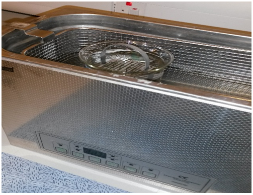 | Figure 1. Precision ultrasonic cleaning device |
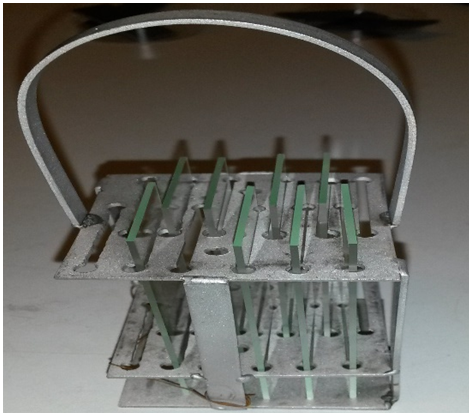 | Figure 2. Microscopic glass rack |
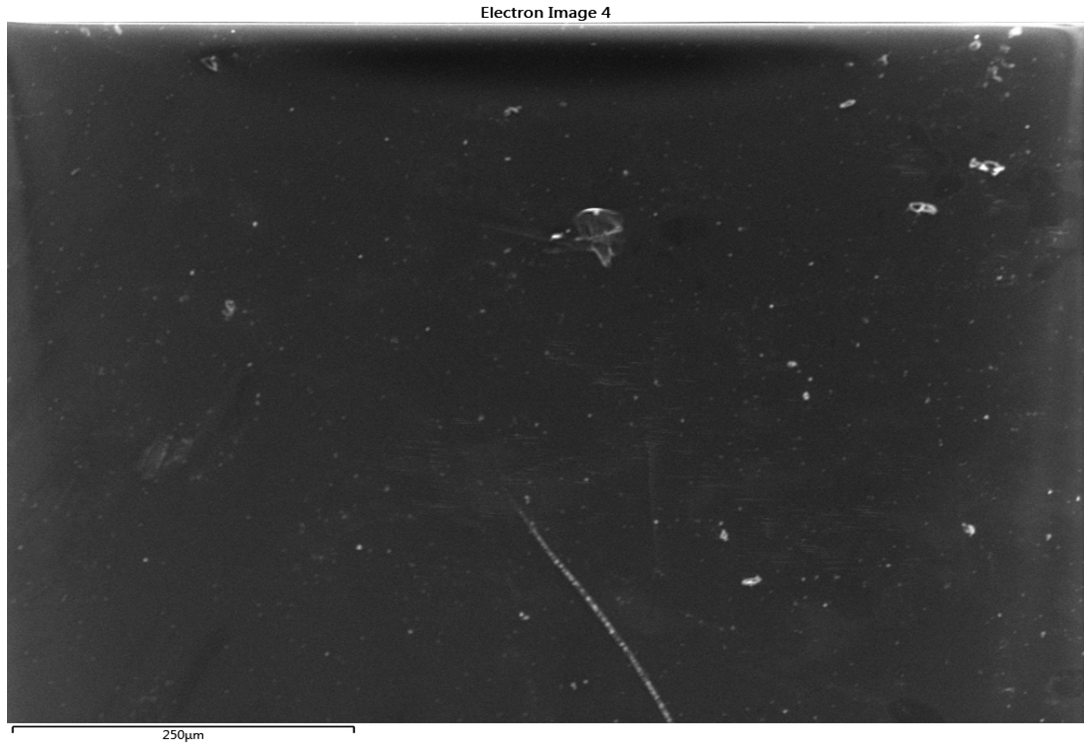 | Figure 3. 120µm SEM micrograph of uncleaned glass substrate @120 magnification (scale bar: 250µm) |
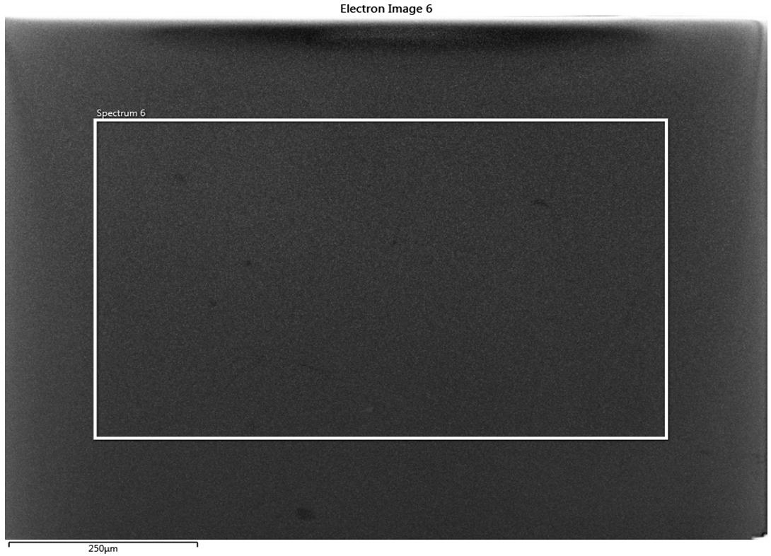 | Figure 4. 120µm SEM micrograph of cleaned glass substrate @120 magnification (scale bar: 250µm) |
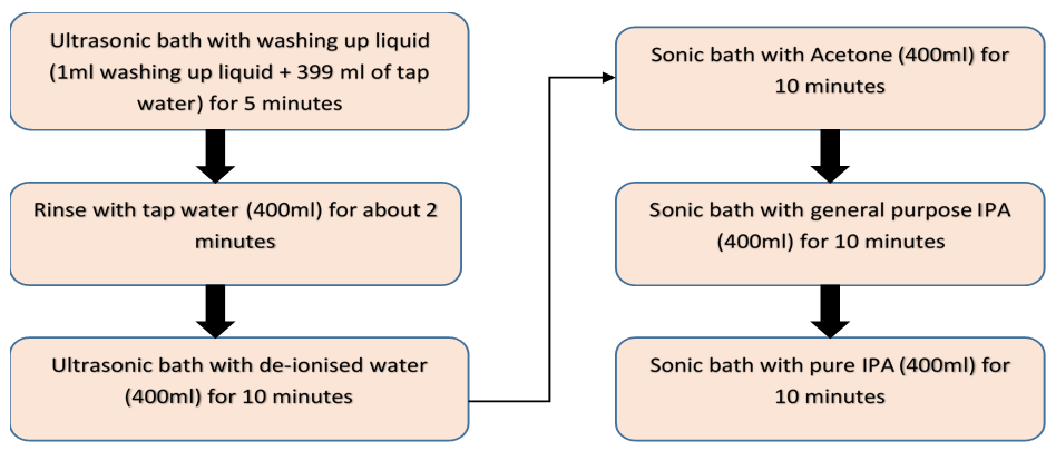 | Figure 5. Process flow of the glass cleaning |
2.2. Silver Thin Film Deposition
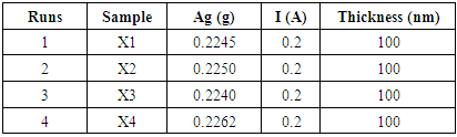
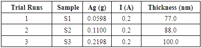
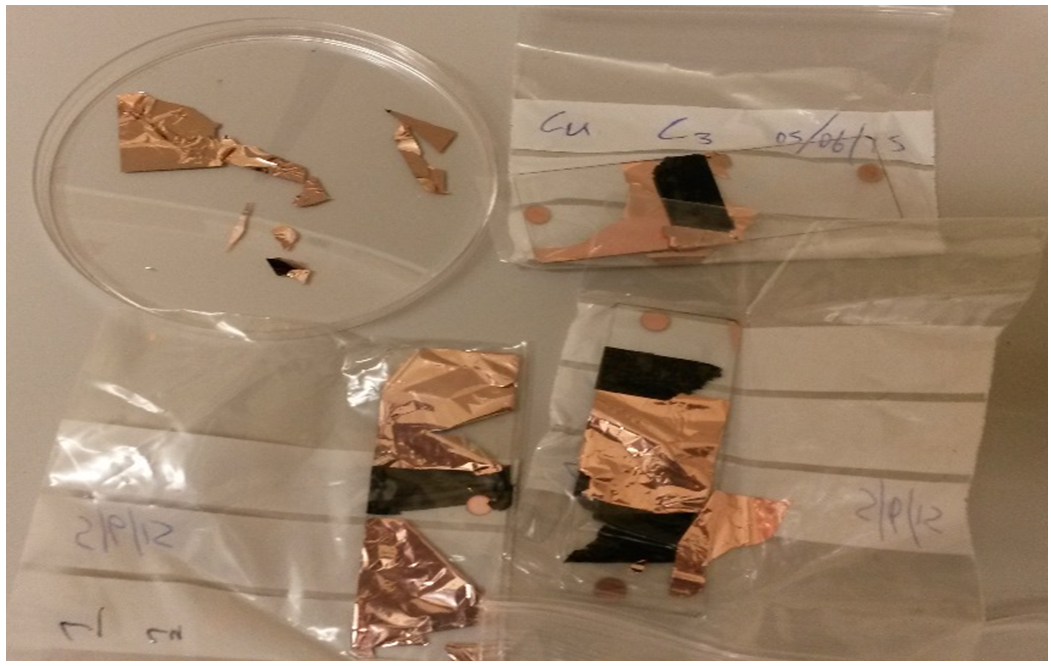
- Thermal evaporation (a PVD technique) was employed in the deposition of Ag thin film. Silver metal utilised in this study is the 0.25 mm Ag wires (AGE406) of 99.99% purity from Agar Scientific, United Kingdom (UK). Prior to coating, the Ag wire was first weighed for each run with Sartorius electronic weighing balance. This process was applied to each experimental trial in order to determine the actual weight for the desired thickness to be deposited.The Ag metal coatings were deposited at a current of 0.2 A with the evaporating boat with melting temperature range of 1400°C – 1800°C. These temperatures are high enough to melt the Ag lumps as the melting temperature of Ag is known to be 192°C (Silver, 2015). Four different samples (X1 …… X4) were prepared (Table 1) with the appropriate calibrated thickness of 100 nm Ag deposited (Figure 6 and Figure 7). The weight of the Ag was determined using Sartorius electronic balance prior to deposition, after which the thickness of the film was analysed with Dektak surface profiler.
|
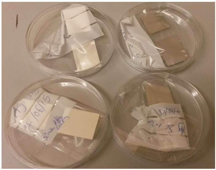 | Figure 6. Silver coating at 100 nm film thickness |
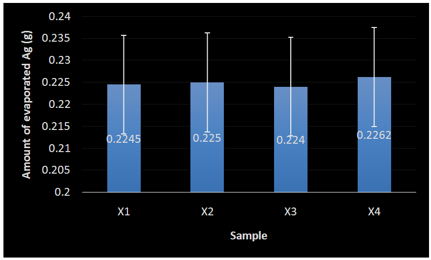 | Figure 7. Mean deviation/Error bar plot of evaporated Ag |
|
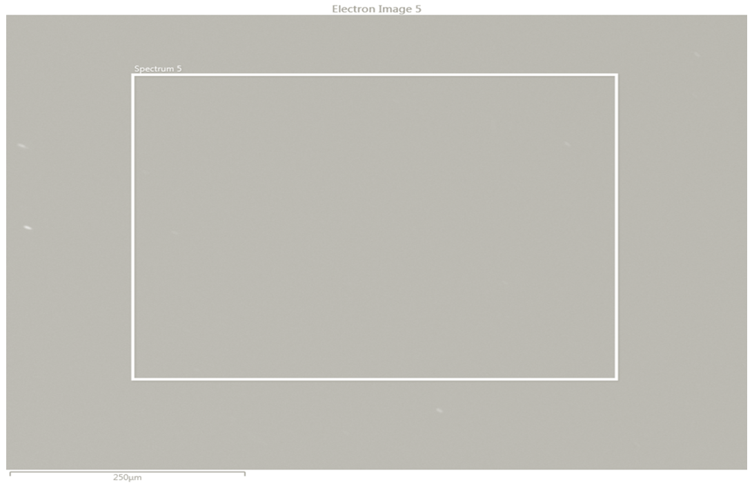 | Figure 8. SEM Micrograph of Ag surface analysed same day after coating 250µm @ 150 magnification (scale bar: 250µm) |
 | Figure 9. SEM Micrograph of Ag surface analysed 1 day after coating 250µm @ 150 magnification (scale bar: 250µm) |
2.3. Copper Thin Film Deposition
- Sputtering was adopted to deposit Cu thin film onto the Ag coated surface using 99.99% pure copper target (AG 8077) purchased from Agar Scientific, UK. The first set of Cu deposition was carried out in order to determine the growth rate; this run lasted for 45 minutes resulting to thickness yield of 1700 nm (measured with Dektak Profilometer). This 1700 nm-Cu film suffered severe delamination (Figure 10). This might be due to stress build-up, and hence it is not advisable to deposit very thick films unto glass reflectors, as this will encourage poor adhesion and bonding of the Cu film with the substrate.
 | Figure 10. Copper coating delamination at 1700 nm film thickness |
 | Figure 11. Copper coating at 50 nm film thickness without any delamination |
2.4. Paint Deposition
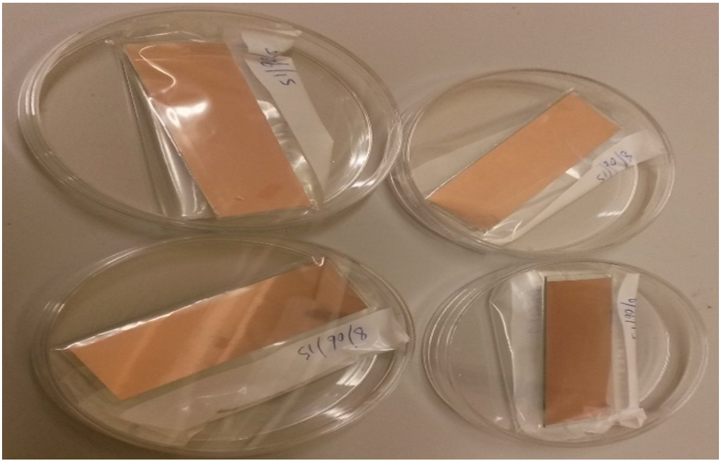
- In order to protect the developed mirror (reflectors) coatings, Pb based paint was employed to back the coated Cu layer. The paint deposition was carried out in a fume hood using a hand roller of 24µm pitch. Paint thickness of 54µm was deposited as measured with Dektak® Profilometer. The percentage of Pb in the paint was confirmed to be 7.5% using EDS elemental mapping (Figure 12). The choice of Pb paint as the reflector backing material was due to the perceived ability of Pb to withstand corrosion.
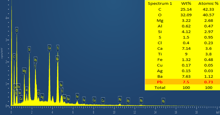 | Figure 12. EDS elemental mapping showing 7.5% of Pb in the paint composition |
3. Results and Discussions
3.1. Compositional, Structural and Morphological Properties
- The elemental mapping of the chemical constituents of the coated reflector samples was carried out using EDS. The physics of electron emission described by Max Planck is the basis for the EDS spectral composition analysis (Almanza et al., 1992; Feng et al., 2003; Wasa et al., 2004: Kennedy and Price, 2005 and Dobrzañski et al., 2007).Since each chemical element has its characteristic emission line spectrum, the line spectra is determined by the energy levels present. Figure 12 also shows the EDS micrograph of the coating with the presence of Ag, Cu and about 7.5% of Pb recorded; the other elements present were due to the glass substrate (as shown by high % of Si) and the paint composition.Figure 13 shows the structural micrographs of the coated reflectors obtained using high resolution SEM capable of producing 1 nm image magnification. The carbon present must be due to the graphite tape used on the sample prior to loading to ensure that it gets charged for the SEM/EDS analysis. With SEM many samples can be focused at the same time due to its large depth of field, H, usually represented as given in equation 1:
 | (1) |
 = minimum distance the eye can focus on photograph (m); Wd = distance between the lens and specimen (m); M = selected magnification; A = selected aperture (f/D).
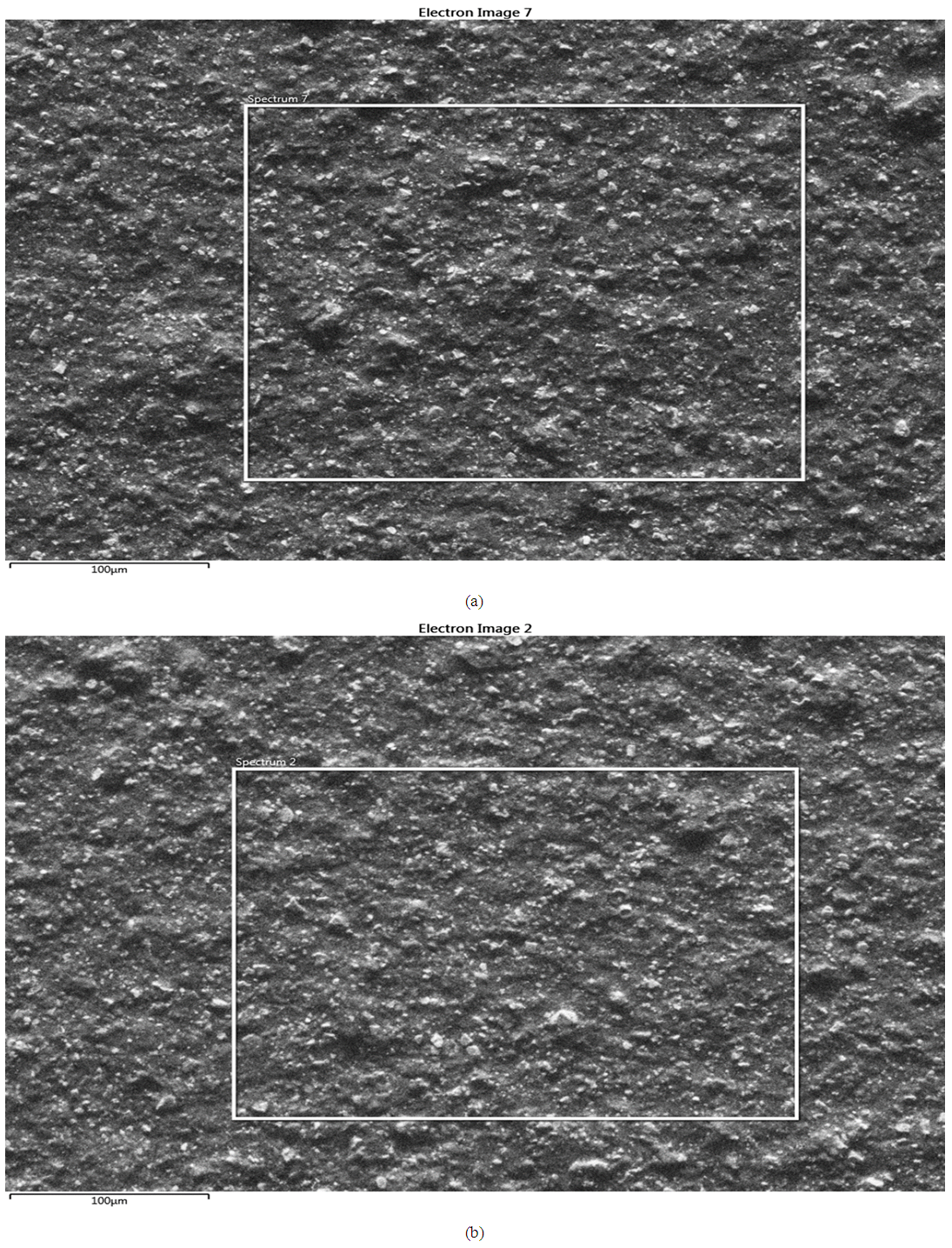 | Figure 13. SEM micrograph of the coated reflector samples (a) and (b) at 250 magnification (scale bar: 100µm) |
3.2. Optical Properties
- The optical characteristics of the developed solar reflector were analysed using V670 (UV/VIS/NIR) Jasco spectrophotometer. The principal property investigated is the reflectance (reflective performance) of the reflector. The optical measurement covered wavelength spectra of 200 nm – 2500 nm (i.e the ultraviolet, visible and near infrared band spectra). A 60 mm integrating sphere holder was used for measuring the reflectance. The actual reflective ability of the mirrors were recorded after taking the baseline measurement (Figure 14) by positioning a standard spectralon white plate into the light propagating part of the sphere.
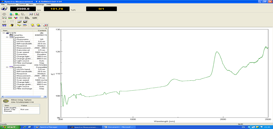 | Figure 14. Reflectance baseline measurement with spectral on white plate |
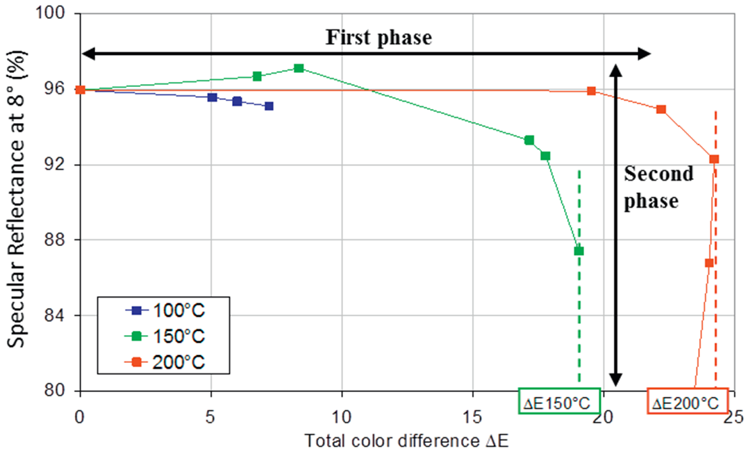 | Figure 15. Reflectance of a silver coated reflector as a function of colour change, ΔE (Raccurt et al., 2014) |
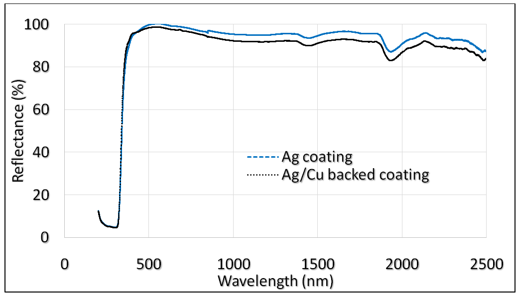 | Figure 16. Ag coating and Ag/Cu backed coating reflectance |
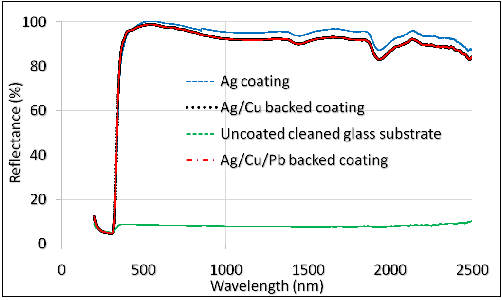 | Figure 17. Ag/Cu/Pb backed developed reflectance |
4. Conclusions
- In conclusion, a quite novel Cu and Pb paint protected Ag thin film reflector was successfully fabricated. The Ag thin films were deposited on the cleaned glass substrate using thermal evaporation while the Cu thin films (protective-backing) were deposited on the Ag layer via sputtering; and the Cu layer finally sealed with Pb-based paint as an anti-corrosive layer. Spectral analysis of the developed reflectors’ optimised structure of glass/Ag (50 nm)/Cu (100 nm)/Pb-paint (54µm) showed high reflectance of 96 – 99% within the electromagnetic band spectrum of 400 – 700 nm. This nanoscale coatings have demonstrated the potential application of the reflector in concentrated solar thermal power manufacturing.
ACKNOWLEDGEMENTS
- The authors want to thank Dr. Christine Chalk, Dr. Jeff Rao, Dr. Tracy Roberts, Dr. Tim Pryor of the Surface Engineering and Nanotechnology Institute (SENTi) and Dr. Chris Shaw of the Materials & Nanotechnology Laboratory, Cranfield University, United Kingdom for their support during the laboratory phase of this research; and Tertiary Education Trust Fund (TETFund), Nigeria, for sponsoring Christian Nlemchukwu Nwosu for training in Cranfield University, UK.