-
Paper Information
- Paper Submission
-
Journal Information
- About This Journal
- Editorial Board
- Current Issue
- Archive
- Author Guidelines
- Contact Us
International Journal of Energy Engineering
p-ISSN: 2163-1891 e-ISSN: 2163-1905
2017; 7(1): 28-31
doi:10.5923/j.ijee.20170701.02

Solar Energy Plants’ Sun Tracking Systems’ Experimental Results and Energy Calculation
 Abstract
 Reference
 Full-Text PDF
 Full-text HTML
F. F. Mammadov
Azerbaijan State Oil and Industry University, Baku, Azerbaijan
Correspondence to: F. F. Mammadov, Azerbaijan State Oil and Industry University, Baku, Azerbaijan.
| Email: |  |
Copyright © 2017 Scientific & Academic Publishing. All Rights Reserved.
This work is licensed under the Creative Commons Attribution International License (CC BY).
http://creativecommons.org/licenses/by/4.0/

In the paper the sun tracking systems’ usage for high-potential concentrators and solar PV to be directed to the sun have been studied due to the cographical location of Absheron peninsula.
Keywords: Sun tracking system, Azimuth, Zenith, Solar energy plant, Solar PV
Cite this paper: F. F. Mammadov, Solar Energy Plants’ Sun Tracking Systems’ Experimental Results and Energy Calculation, International Journal of Energy Engineering, Vol. 7 No. 1, 2017, pp. 28-31. doi: 10.5923/j.ijee.20170701.02.
1. Introduction
- According to the geographical coodinates, for the perpendicularity provision of the for high-potential concentrators to teh sun along the day we should take into considration ist action on azimuthal and zenithal surface:In the paper diurnal sun rays’ density has been determined on the concrete area. The direct sun rays
 amount falling on the surface under
  angle is to be defined [1, 2]:
 Here,
Here,  - solar radiation constant which equals the energy amount coming from the Sun to the Earth.
  - correcness ratio being used for sun rays’ passing through the atmosphere (air mass);
  - falling angle of sun rays directly on the surface.
  Here,
Here,  - the angle of the solar PVs in comparison with horizon;
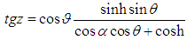
  - the sun height angle within the exact time. After these parameters motion trajectory can be calculated on the azimuthal surface of the concentrator [3].Concentrator movement on the azimuthal surface has to be same with conspicuous sun angle speed. For this azimuthal motion velocity should be expressed as follws:
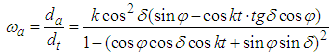 Here,
Here,  - hour angle from midday;
 - inclined angle of the sun;
 - geographical parallel of the area. Annually the greatest azimuthal motion rate occurs in June 21, the smallest one happens in December 21. For that, maximal azimuthal movement rate is to be defined as below:
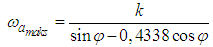 The total power of the electric motor which makes the concentrators move on azimuthal surface must be determined like this:
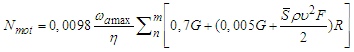 Here,
Here,  - efficiency of whole mechanism having role in the guiding system;
 -quantity of the every part consisting of concentrators with pieces;
 - coun of the concentrators in each part with pieces;
 - weight of the concentrators
 - air density
 wind speed
 - surface square of the concentrators
 - radius of the motion path on azimuthal surface
 - the measured ratio on the aerodynamic resistance of each concentrator and has to be determined as follows [4]:
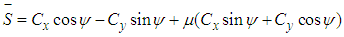 Here,
Here,  - aerodynamic ratio;
 - shaking coeffient during themovement;The impact of the aerodynamic forces on the concentrator surface should be calculated as below [5, 6]:
 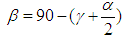 Here,
Here,  - angle between central axe of the concentrator and wind direction;
 bewteen central axe of the concentrator and direction to the center. Due to this calculation
  is defined as below:
 According to the calculations carried out I should say that the force of demanded electric motor consists of 0,3% from the total energy during concentrator mvement on azimuthal surface. The energy system possessing solar PVs may be used for the electric motor work. Thia’s why averagely solar PV having 300 W power, 2 accumulators and a controller are necessary. Provision of concentrators’ movement on zenithal surface annually depends on days, months and the sun height due to the geographycal location, relief of the territory. Naturally the Sun height angle is able to be distingiushed in the mention area in the stationary point taking into considration the geographical location and territory relief. Identidfication of these angles is realized to the following formular [7-9]:
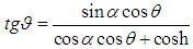
 Here,
Here,  angle between sun ray reflected from the concentrator surface and the horizontal surface. Due to the realized calculation I dare say that the above mention parameters should be taken into considration for the concentrators to move on the both surfaces. But depending on geometrical shape of the concentrators (parabolic, parabolo trough, flat and others) it shoud be done. For egxample parabolo through concentrator can move on only zenital surface. For this 2 conditions must be followed. The first one is that the row of the parabolo through has to be horizontal on the length. The second condition is that the central axe of the concentrator is to be directed to the maximum sun height angle depending on the geographical parallel. In the second variant some mistakes appear that it influences negatively to the work regime of the concentrator. In order to calculate the deffects and determine the optimal showing the next equation is used:
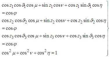 Here, I dare say that, movement of the concentrator aord its axe is to be realized by the transient angle rate. Therefore, ondulating angle speed can be determined as below [7]:
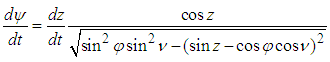 During the provision of rotation in the concentrator axe, number of gears
  of the mechanism depends on the maximal datum. Therefore, the general number of gears of the mechanism can be defined like this:
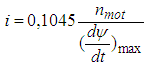 Here,
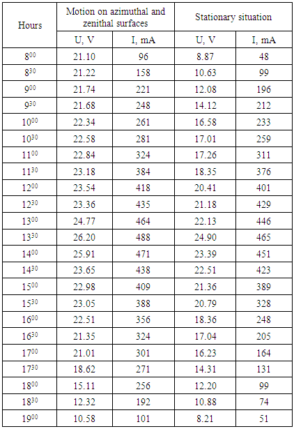
Here,  - rotary speed of electric motor, rotation/sec.After the current experiments [10] at the result of the calculation due to the above mentioned method in some territories summeries on azimuthal and zenithal surface angles of the solar concentrators while directing to the Sun and risk situation have been obtained. On the base of the experiments carried out in the southen-east and the suther-west parts of Absheron peninsula on the both surfaces dependence between surface angles and day time has been detected. At the next table rotational angle data on the both azimuthal and zenithal surfaces of the solar concentrators were given for summer in the territry of the southen-east and the southen-west parts of Absheron peninsula.
|

|
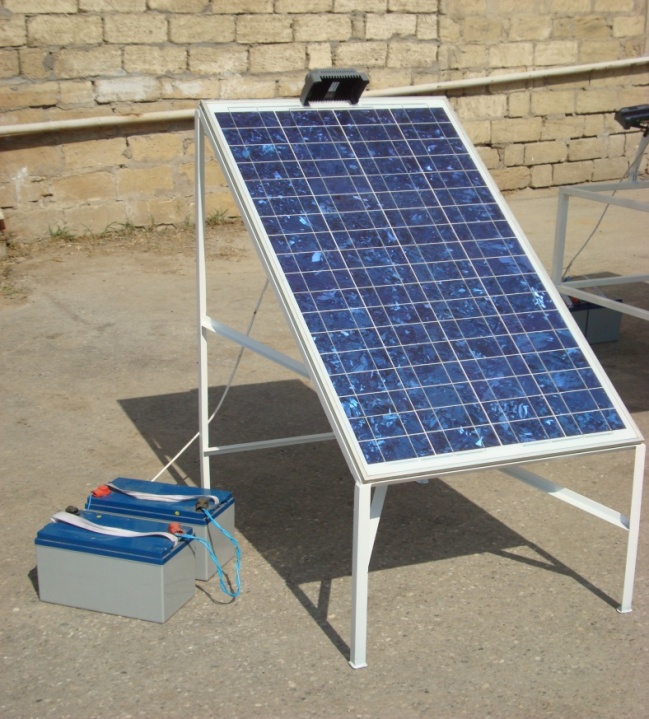 | Picture 1. Solar PVs, controller and accumulator |
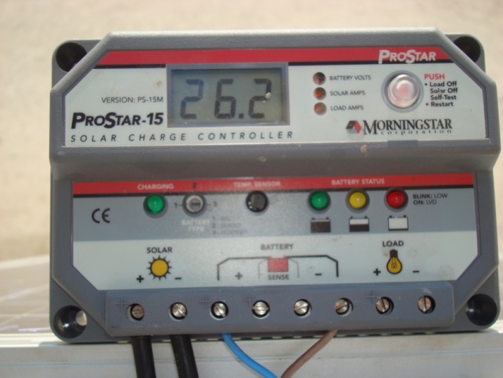 | Picture 2. Controller from Prostar-15 mark |
2. Results
- Summerizing experimental results the following results have been revealed:• Maximal energy efficiency state of the device;• High energy potential and effectivness for the plant;• Advisable areas of Absheron peninsula for the energy plant usage;• Engine capacity of the electric motor;• Suitable geographical location parameters for the test;• Time (from... to) for the optimal work regime;• Perpendicularity duration on the Sun; • Necessity to the sun tracking system to get more power.Indeed the experiments and tests give opportunity to develop the ways to obtain much more energy efficiency at the solar plants by using suntraking systems.