-
Paper Information
- Paper Submission
-
Journal Information
- About This Journal
- Editorial Board
- Current Issue
- Archive
- Author Guidelines
- Contact Us
International Journal of Energy Engineering
p-ISSN: 2163-1891 e-ISSN: 2163-1905
2015; 5(4): 67-73
doi:10.5923/j.ijee.20150504.01
An Energy-Saving Control System of Lighting and Air-Conditioning Linked to Employee’s Entry/Exist in the Zone of the Office
 Abstract
 Reference
 Full-Text PDF
 Full-text HTML
Yosuke Kaneko1, Masahito Matsushita1, Shinji Kitagami2, Jun Sawamoto3, Tetsuo Shiotsuki4, Tatsuji Munaka5
1Information Technology R&D Center, Mitsubishi Electric Corporation, Kanagawa, Japan
2Mitsubishi Electric Building Techno-Service Co. Ltd., Tokyo, Japan
3Department of Software and Information Science, Iwate Prefectural University, Iwate, Japan
4Department of Robotics and Mechatronics, Tokyo Denki University, Tokyo, Japan
5School of Information and Telecommunication, Tokai University, Tokyo, Japan
Correspondence to: Jun Sawamoto, Department of Software and Information Science, Iwate Prefectural University, Iwate, Japan.
| Email: |  |
Copyright © 2015 Scientific & Academic Publishing. All Rights Reserved.
We have developed an energy-saving control system that controls lighting and air-conditioning considering desk allocation in the office. This lighting control system makes the desk area that a person uses brighter, but makes the lighting gradually dimmer with distance from the person at a desk. In addition, the air-conditioning system controls temperatures only for areas where someone is at the desk, which can be done by controlling the on and off time of the thermostat in the air-conditioning system. We evaluated this control system by actual measurement and simulations and validated its effectiveness for the reduction of electrical power consumption.
Keywords: Lighting, Air-Conditioning, Energy-Saving, Office
Cite this paper: Yosuke Kaneko, Masahito Matsushita, Shinji Kitagami, Jun Sawamoto, Tetsuo Shiotsuki, Tatsuji Munaka, An Energy-Saving Control System of Lighting and Air-Conditioning Linked to Employee’s Entry/Exist in the Zone of the Office, International Journal of Energy Engineering, Vol. 5 No. 4, 2015, pp. 67-73. doi: 10.5923/j.ijee.20150504.01.
Article Outline
1. Introduction
- Energy consumption in office buildings is increasing. Lighting and air-conditioning account for the majority of power consumption in the office. Therefore, energy conservation methods of these facilities are important. To achieve energy-saving of the lighting without impairing comfort in the office, it is effective approach to turn off the lighting in the unnecessary area, and to keep appropriately illuminance. Therefore, conventional studies have proposed control systems that turn off lighting automatically in the unoccupied area using a motion sensor and control brightness using illumination sensors for the occupied area [1-3]. In addition, other conventional studies have decided brightness of the area where persons are detected by optimizing method [4] [5]. Regarding the energy saving of the air-conditioning, a conventional method detects a change in occupancy by motion sensors and control to turn on or off of the air-conditioning [6]. In addition, another study has been done to divide the office floor and control only those zones for which someone is at a desk to satisfy the target room temperature [7]. As discussed, in conventional studies, energy conservation is achieved by controlling lighting and air-conditioning only in the area of the office floor where someone is at the desk and only when someone is there.As described in this paper, we propose an energy-saving system that can reduce the area in which brightness and temperature should be satisfied while keeping the target brightness and the target temperature. This proposed system pinpoints locations where brightness and temperature should be satisfied. At this time, the proposed system detects a person in the floor in cooperation with an access control system without using motion sensors. Furthermore, the proposed algorithm controls lighting and air-conditioning to maintain the brightness and the temperature of the locations. We evaluated the proposed system with a simulation and an experimental evaluation. As the results, we verified that the proposed system can reduce power consumption compared with the conventional means while maintaining the brightness and the temperature where someone is there.
2. Background
2.1. Features of Office Lighting
- The lighting power consumption accounts for about 19% of the total of the commercial sector in the US [8]. And, its usage pattern remains almost constant throughout the year. Therefore, it is possible to obtain a large energy-saving effect throughout the year by applying the energy-saving methods for office lighting. While, in an office building, employee are constantly entering and leaving a floor, so lighting systems may turn on the zone where there is not a person. So, it is an effective approach for reducing the waste to control equipment using the entering and leaving information such as the number of employee in a floor, and the presence or absence.Meanwhile, with the increase in the security consciousness in company, more access control systems are installed into office buildings. While the primary function of the access control system is to control the entry and exit of persons, it can also be utilized as a means to grasp the entry or exit information such as the presence or absence of persons in the rooms.
2.2. Features of Air-Conditioning
- The air-conditioning exhausts about 65% of the total power consumption consumed by a building in the US [9]. In general, an air-conditioning system controls room temperature at a certain level by its autonomous control. However, control methods in the general air-conditioning system do not consider whether someone is at the desk or not. Therefore, it sometimes maintains temperatures wastefully even in areas that no person is using. Another control method aside from the autonomous control of the system is rotation control. The rotation control divides an office floor into N number of groups, each with indoor unit. The system achieves energy conservation by switching the thermostat on and off. By application of this control method, we can achieve energy conservation by switching the thermostat on and off depending on whether someone is at a desk or not. However, even in the same office floor, the room temperature might vary depending on the distance from ducts and windows. Therefore, in this rotation control, it is necessary to determine the time interval between the thermostat switching on and off by consideration of the variation of the room temperature in the office, which is crucial also from the perspective of maintaining the target room temperature.
3. Proposed Method
- This paper describes the “energy-saving control system of lighting and air-conditioning linked to employee’s Entry/Exist”, which uses entry and exit information obtained from the access control system and the seat position information of each person. And, the system controls automatically lighting and air-conditioning so that each equipment are turned on only in the required area and for the required time ensuring a certain amount of illuminance only on and around desks people are sitting.
3.1. Structure of a Proposed System
- Figure 1 illustrates the structure of a proposed system. This system consists of the access control system (ACS), the lighting control system, the air-conditioner control system, and the energy-saving control server. These systems and the server are linked over the network.The ACS consists of an authentication device and some card readers. The ACS is equipped with two types of card readers for entry and exit at each door on a floor. When employee passes a door, he passes IC Card over the card reader. Thereby, the information of the employee who has passed a door is sent to the energy-saving control server through the authentication device.
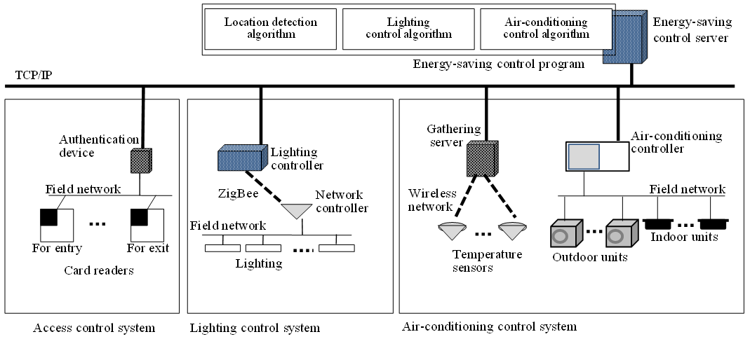 | Figure 1. Structure of the proposed system |
3.2. Detection Method of the Person’s Location in the Floor
- The location detection algorithm detects the presence or absence of employees in the floor with data sent by the ACS. When employee is out of the office floor, he passes IC Card over the card reader for exit. As a result, the door opens. On the other situation, when employee goes into the office floor, he passes IC Card over the card reader for enter. By these actions of employees, the location detection algorithm is able to identify employees entering and leaving a room. The data to identify each employee are included in each IC Card. These data are sent to the location detection algorithm when employee passes IC Card. Thus, this algorithm is able to detect presence or absence of employees in the floor. In addition, the proposed system grasps seat position information of each employee. The proposed system detects positions where employees are at.
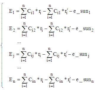
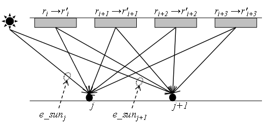
3.3. Lighting Control Algorithm
- The lighting control algorithm controls lighting fixtures by the two phases. We describe these phases in detail below.(1) 1st phase. The energy-saving control server detects employee within a floor. And then, it specifies the zone that should be illuminated, using seat position information. The lighting fixtures are turned on and the dimming rates are controlled only around the zones where persons are in. As the distance from the zones increases, brightness will decrease. For example, as shown in Figure 2 (a), the dimming rate of a lighting fixture within one meter from each person are set to 75%, and the lighting fixtures within two meters are set to 25%. Through this dimming control, zones near the persons are kept bright, and a sharp decrease in brightness is prevented. In addition, the lighting fixtures near persons who have gone home or who are away from their desk for a meeting are automatically turned off.
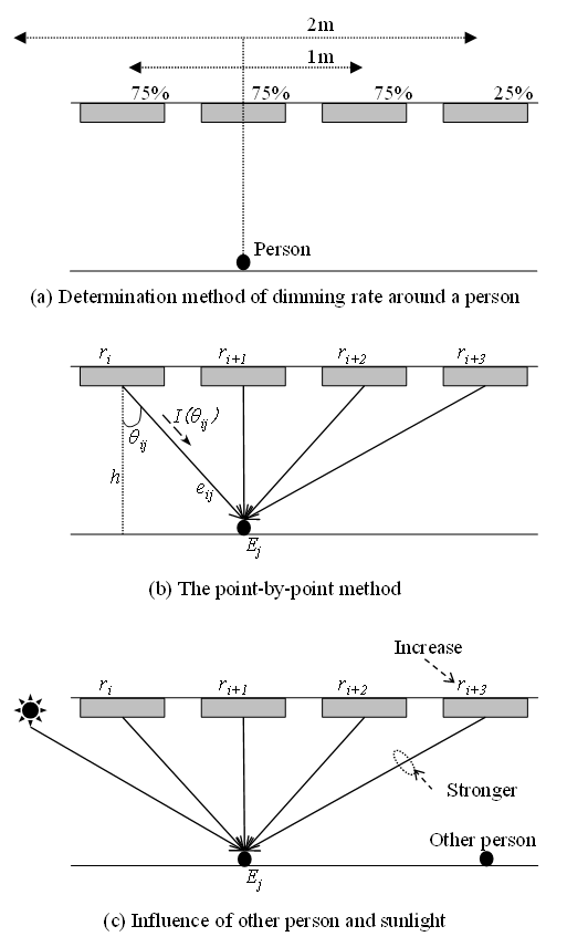 | Figure 2. Lighting control algorithm 1st phase |
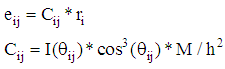 | (1) |
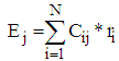 | (2) |
 | (3) |
 | Figure 3. Lighting control algorithm 2nd phase |
3.4. Air-Conditionings Control Algorithm
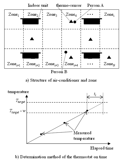
- In this proposed method, by considering the fact that heat transfers to each location unevenly, it controls the thermostat on and off to maintain the target room temperature where someone is in the zone. (1) Structure of air-conditioning control function and operation outline. Figure 4 shows a structure and operation outline of the air-conditioning control function. Figure 4 (a) shows the ground plan of the floor, and also the figure shows the positions of the air-conditioners, the positions of the persons, and the positions of the thermo-sensors. As portrayed in Figure 4 (a), the proposed method divides N number of zones in the whole office floor. Dotted lines shows zones. Moreover, in the proposed method, a movable thermo-sensor is to be installed in each zone. (2) Method of switching a thermostat on and offIt determines the timing of turning the thermostat on and off at each group, which is done by the variation of the reading value at the thermo-sensor that is installed in the zone. The determination method in the case of heating is shown below.1) Figure 4 (a) shows that Person A is at Zone4 and Person B is at Zonei+4. This proposed method sets the target temperature as Ttarget and the tolerance of the target temperature as w. In short, it controls the thermostat on and off to maintain the temperature, Ttarget ± w in the zone being used by someone.2) This proposed method turns the thermostat on in the air-conditioning until the room temperature for the zone i reaches Ttarget. Figure 4 (b) shows the time necessary to turn the thermostat on to reach Ttarget. In this Figure, the X-axis shows elapsed time after the air-conditioning has turned into thermostat on, the Y-axis shows the measured value of the thermo-sensor. First, measure the room temperature until it exceeds Ttarget – w when turning the thermostat on. When the room temperature exceeds Ttarget – w, set the thermostat on time ti that requires the room temperature to reach Ttarget. This proposed method enables zone i to reach the target temperature by turning the thermostat on during time ti toward the zone to which person i belongs. Subsequently, turn the thermostat off at each zone.3) This proposed method controls air-conditionings to maintain room temperature of zone i in the range of Ttarget ± w. The method monitors a temperature sensor that installed in the zone i continuously and switches the thermostat off when room temperature Ti_b which the method measured this time decreases than the value Ti_a which the method measured last time. Conversely, the method switches the thermostat on when Ti_b rises than Ti_a. In addition, when Ti_b is lower than Ttarget - w, the method assumes thermostat on. And the method switches the thermostat off when Ti_b is higher than Ttarget – w.
 | Figure 4. Air-conditioner control method |
4. Evaluations and Considerations of the Proposed Method
- In order to evaluate an effectiveness of the developed technology, we built a simulator and a prototype system.
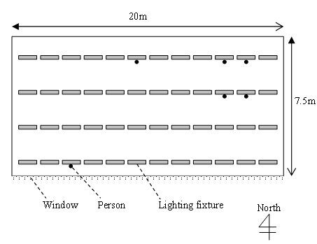
4.1. Lighting Control Method
- We evaluate the proposed lighting control algorithm by the simulator. Figure 5 shows an evaluation condition. The size of the room is 20 by 7.5 meters, and 48 lighting fixtures are installed. A window is installed in the south side of the room, and the sunlight pours into the room. As this evaluation condition, we assume that right under lighting fixtures of the southernmost line are affected by 100lx by the sunlight. And, we assume that there are six persons in the room.
 | Figure 5. Evaluation condition of the lighting control |
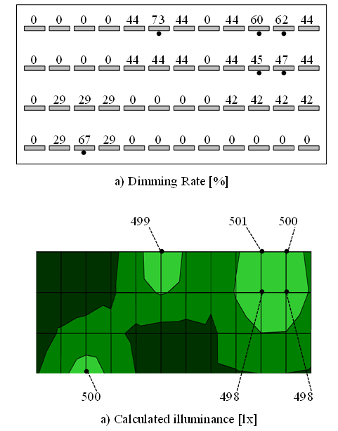 | Figure 6. Simulation result of the lighting control |
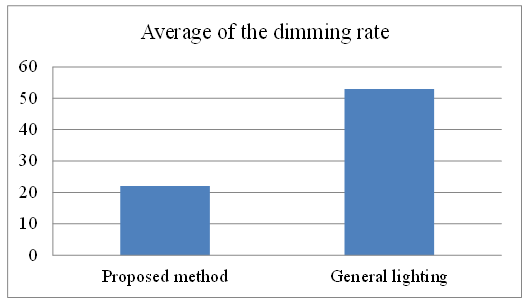 | Figure 7. Average of dimming rate |
4.2. Air-Conditioner Control Method
- We measure room temperature change of the zone where someone is in and the power consumption to evaluate the proposed method. We evaluate it based on a comparison with automatically control of the air-conditioner. Figure 8 shows an evaluation condition. The size of the room is 14 by 8.5 meters, and 4 indoor units are installed. And, the room is divided in the several zones as shown in dotted lines. We assume that there is one person in the Zone1, and we operate the proposed method and automatically control. In addition, the target temperature in the zone where someone is there is 22.0 degrees Celsius.
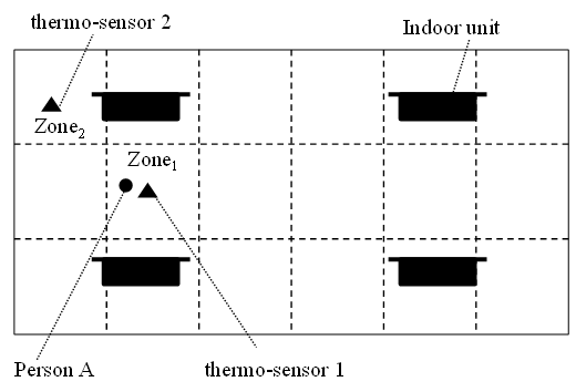 | Figure 8. Evaluation condition of the air-conditioner control |
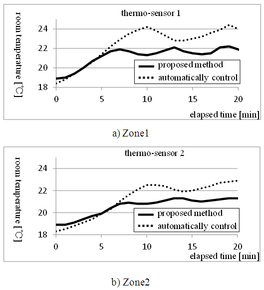 | Figure 9. Room temperature changes on zone1/zone2 |
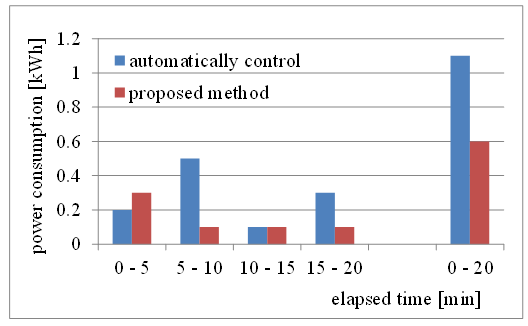 | Figure 10. Power consumption of air-conditioner |
5. Conclusions
- In this article, we mentioned to control the lighting system and the air-conditioning system for the only zone where someone is in. We evaluated the proposed lighting control algorithm by simulation and confirmed that the proposed algorithm got the energy saving effect while keeping the target illuminance of the zone where person is in. In addition, we evaluated the proposed air-conditioning control algorithm by the experimental evaluation and confirmed that the proposed algorithm got energy saving effect while keeping the target room temperature of the zone where person is in. By the above, we confirmed that the proposed method is effective for the energy saving of office buildings.