Joseph S. A.1, Odiba O.1, 2, Ajise K. A.1, Yakubu A. M.1, 2
1Prototype Engineering Development Institute, Ilesa, Nigeria
2Federal University of Technology, Akure, Nigeria
Correspondence to: Yakubu A. M., Prototype Engineering Development Institute, Ilesa, Nigeria.
| Email: |  |
Copyright © 2015 Scientific & Academic Publishing. All Rights Reserved.
Abstract
In most developing countries, water is usually sent to storage tanks from underground wells using pumping machines which are electrically driven. When voltage becomes insufficient (low voltage supply) to run the electric motor, its windings start to hum and heat up. If this persists, it may lead to insulation breakdown and burning of the windings.In this design, the pumping machine will stop working in the event of low supply voltage or outright power outage in order to prevent its winding from humming and unnecessary temperature rise.This is made possible by the opening of the relay contact K2. This is an additional provision to the old order where the pump stops when the tank is full or water level in the underground well has fallen to a preset minimum level, and starts when the tank is almost empty or there is enough water to be pumped in the well using float switches as sensors.
Keywords:
Water-pump control, Electrically driven, Low voltage sensor, Insulation breakdown, Humming, Temperature rise
Cite this paper: Joseph S. A., Odiba O., Ajise K. A., Yakubu A. M., Development of A Water-Pump Control Unit with Low Voltage Sensor, International Journal of Energy Engineering, Vol. 5 No. 2, 2015, pp. 34-39. doi: 10.5923/j.ijee.20150502.03.
1. Introduction
The water crisis is the number one global risk based on impact to society and the number eight global risk based on likelihood [12]. An estimated 750 million people around the world lacks access to safe and portable water [13] and a large percentage of this population is concentrated in the developing countries.In the bid to overcome this shortage in the supply of portable water, a number of sources have been explored which include the use of underground water wells but this also comes with its own challenges.In this paper, we are out to design a water-pump control unit with low voltage sensor to help reduce some of these challenges associated with the availability of portable water.In the normal operation of the water-pump control with low voltage sensor, the low-voltage circuit monitors the incoming public supply voltage to detect when the voltage drops below a level that can damage the pumping machine. In this case, 190 V is the limit at which the unit stops the water pump from working until the voltage normalises again.The sensor stage monitors the unregulated voltage drop across R2 of the comparator stage and compares it with a fixed reference voltage across R3. The drop across R2 at 190 V a.c is set as the reference. Any voltage drop below this sends a LOW to the input of the D-flip-flop to switch the transistor OFF in reset mode. Once the transistor switches OFF, the relay is de-energized and its contacts changes over to switch OFF the water pump. The water pump is connected through the normally open contact of the relay. When the voltage goes back to normal, the voltage drop across R2 becomes higher than that across R3, hence, a HIGH signal is sent to the the D-flipflop to energize the relay by switching ON the transistor. This way, the pump starts working again in set mode.The introduction of the 4013-segment logic device is to ensure a perfect switching and eliminate fluctuation, which is synonymous with voltage comparators [2]. This fluctuation can be very devastating, as the relays would be switching erratically. The functional block diagram of water- pump control unit is shown in figure 1.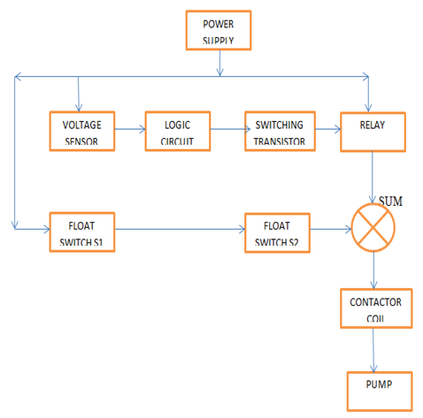 | Figure 1. Functional Block Diagram of the Water Pump Control Unit |
2. Design Calculations
The water pump control unit has two main circuit; the power circuit and the control circuit.The design of these circuits are discussed in this section.
2.1. Power Circuit Design
Figure 2 is the usual set up of the power supply to an electric motor such that:• short circuit protection and disconnection is provided by the miniature circuit breaker,• the operation of the motor is provided by contactor, and• the overload protection of the motor and feeder cable is provided by the overload relay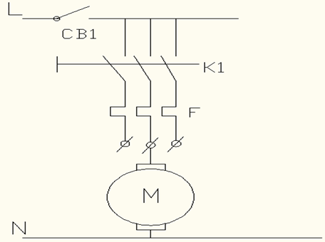 | Figure 2. Power Circuit |
2.1.1. Determination of Miniature Circuit Breaker Rating
The design (figure 2) shows a miniature circuit breaker (MCB) as the first component in the power circuit which serves as the branch protector that protects the whole circuit against overload current due to earth fault or short circuit while the pump is working.The following factors, considered in using a MCB as a short circuit protective device [11];• the MCB breaking capacity must be at least equal to the prospective short circuit current at the point of installation,• the MCB instantaneous trip must be higher than the motor starting peak current and lower than the maximum breaking capacity of the starter contactor,• the MCB thermal trip must have a higher time and current characteristics than the starter over current relay, and• the rated current of the MCB must not be less than the motor full load currentMCB is used as the branch circuit protector for the pump and its control apparatus against short circuit and ground faults; it does not protect against an overload fault as it is designed for fast current rise short-duration events [11].The National Electrical Codes (NEC) stipulates that the circuit and ground fault protective device should be between 150% - 300% of the motor FLC (Full Load Current).The FLC of the power circuit is calculated from the parameters on the name plate of the electric motor. The electric motor used in this design is rated at 1.5 hp, 7.1 A, and 220 V single phase supply. | (1) |
where, Hp is Horse power, V is the motor rated voltage (v), PF is the Power factor and ᶯ = efficiency.The current rating of the Miniature Circuit Breaker (MCB) used as the protective device is calculated by taking the highest MCB Rating range of 300%, | (2) |
2.1.2. Determining Overload Relay Rating
The overload protective device consists of three overload units insulated in series with the three phase leads feeding the electric motor. The full load current rating of the motor is used to determine the overload current rating of the protective device. NEC stipulates that overload relay rating (ORR) should be between115 % and 125 % of FLC and that is the range adopted in this design.Hence, ORR = (115 % - 125 %) of FLC.The range of the overload relay used is 6 A – 13 A.
2.2. Control Circuit Design
The control circuit comprises the low-voltage circuit and float switch control circuit; the design of these two control circuits are discussed in this section:
2.2.1. Low-Voltage Control Circuit
• Power StageThe power stage consists of a transformer and bridge rectifier as shown in Figure 3. The transformer steps down the incoming a.c voltage before it is rectified [1] [8]. If a 220/15V step-down transformer is used in the power stage, the transformation ratio, k is calculated as :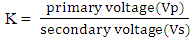 | (3) |
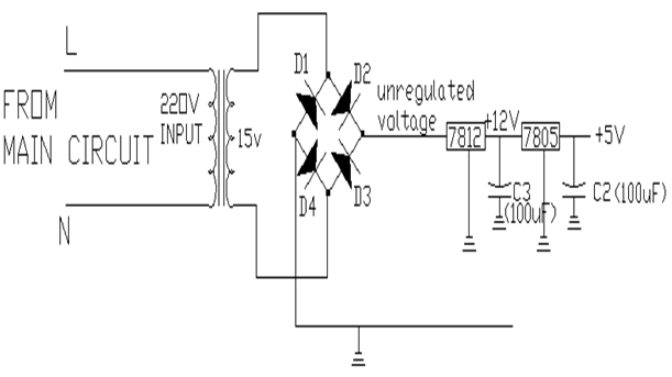 | Figure 3. Power Stage |
The bridge rectifier converts the incoming a.c voltage to unregulated d.c voltage. The values for the unregulated d.c voltage  can be obtained from,
  | (4) |
where Va.c (in) is the input a.c voltage. | (5) |
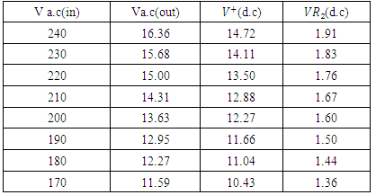
where  is the unregulated d.c voltage.Regulated voltage of 5 V d.c, which serves as the Vcc for the comparator, 555 timer and D-flipflop, is obtained from the LM 7805. Also, the regulated 12 V d.c volatge for energising the 30 A magnetic relay is obtained from the LM 7812. Table 1 shows the unregulated d.c voltages at different input a.c voltages.
Table 1. Variation of unregulated voltage (d.c)] against public supply voltage (V a.c(in))
 |
| |
|
• Comparator Stage A comparator or voltage sensor compares two voltages and gives an output. The comparator stage in this system is used to sense whether the public supply voltage is higher or lower than a preset reference. The input public supply voltage is converted to DC at the power supply stage. The unregulated voltage changes as the public supply input changes. An LM 339 is connected as a comparator to compare the unregulated input to the fixed reference input as shown in Figure 4. | Figure 4. Comparator Stage [10] |
From Figure 4, R1 and R2 form a potential divider that reduces the unregulated voltage to a low voltage of less than 5 V. At 190 Va.c input and let  from
from 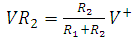 | (6) |
where VR2 is the drop across R2 and V+ is the unregulated voltage. From Table 1 it can be seen that V+ = 11.66V at 190 Va.c input. Let R1 = 100 kΩ,R2 is obtained from equation (6)The various voltage drops across R2 at different input a.c voltages is shown in Table 1.Also, R3 and R4 form another potential divider for the reference.Let the maximum adjustable reference be 3.5 V and let  , hence,voltage drop across R3 is given by;
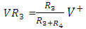 | (7) |
R3 is obtained from equation (7).For the comparator stage, we know that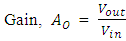 | (8) |
But open loop voltage gain is usually ≥ 20,000For any slightest positive difference in voltage, Vout will drop to V+ since the voltage gain is often very large (of the order of 20,000). When the public supply input tends to go above 1.5 V, the output of the comparator sends a HIGH signal to the D-flip-flop and relay K2 energises to switch on the pump; When it goes lower than 1.5 V, a LOW signal is sent to the D-flip-flop and the relay de-energises to switch off the pump.• Oscillator Circuit The astable oscillator stage is used to generate clock pulses for the flip-flop (synchronous device), since it requires a clock pulse to operate in its SET and RESET modes. An astable oscillator of 1 KHz is used to clock the flip-flop using a 555 timer in this design as shown in Figure 5.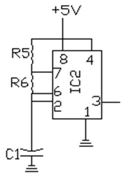 | Figure 5. Astable oscillator Stage [10] |
The astable oscillator circuit generates a continous flow of digital pulses. It has two states but temporarily stable in each state for some times. The switching process between these states generates a continous rectangular waveforms with fast rise times [5].The ON and OFF time of an astable oscillator is given below as  and
and  seconds respectively [2].
 | (9) |
 | (10) |
where; is the oscillator capacitance andR5 and R6 form a potential divider.Oscillation frequency is given as;
 | (11) |
the value of R6 is calculated from equation (11) with a prefered value of 15 kΩ .• The Switching StageThe switching stage comprise the logic control and the switching transistor circuit. The logic control is carried out by the flip-flop and the transistor acts as a switching circuit. Figure 6 shows the circuit diagram of the flip-flop and switching transistor circuit.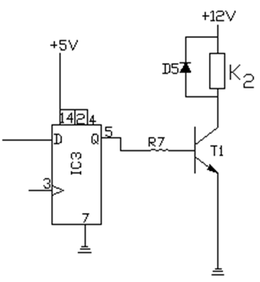 | Figure 6. Switching Stage [10] |
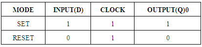
• Logic Control CircuitThe D-flip-flop tells the system when to switch the pump ON or OFF. The operation of the system in both SET and RESET mode is described in table 2 [6]. When the rising edge of the astable oscillator clocks the flip-flop and the output of the comparator is LOW, data shifts from input (D) to output (Q) to switch OFF the pump. When the rising edge clocks the flip-flop and the comparator sends a HIGH to the flip-flop input, the pump is switched ON.Table 2. D-Flip flop’s truth table
 |
| |
|
• Switching Transistor Circuit The switching circuit,as shown in figure 6 consists of a transistor and a relay. The relay is energised and de-energised by the transistor according to the command fed into it from the D-flip-flop. The transistor operates in the class A mode as a switch [8]. The relay is switched on when the flip-flop is in SET mode and vice-versa. Since the relay is an inductive load, a diode D5 is required to protect it from the destructive effect of back EMF.The collector and base resistors are calculated from equations (12) and (13) respectively [4]: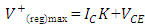 | (12) |
 | (13) |
Also, the base and collector currents are obtained from the current gain as: | (14) |
where;VCE = Collector-Emitter voltageIC = Collector currentK2 = Collector resistanceVBE = Base-Emitter voltage (silicon transistor)IB = Base currentR7 = Base resistorhfe = current gain = max. regulated voltage
 = min. regulated voltageFor perfect switching of the transistor in saturation, it is necessary to include a base resistor. A 400 Ώ relay coil is connected on the collector of the transistor which represents the collector resistance K2.When the transistor is switched ON, VCE is 0 VThe complete circuit diagram of the low-voltage circuit is shown in Figure 7. The figure shows how input signal moves from the first stage to the last stage which results in the closing or otherwise of the relay.
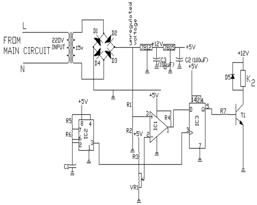 | Figure 7. Low-Voltage Control Unit [10] |
When the input to the comparator is higher than the fixed reference of 1.5 V d.c, due to the presence of power supply, a high signal would be sent to the D-flip-flop, which in turn sends a high signal to energize the relay K2 and the pump switches on.On the other hand, if the input to the comparator falls to a value less than the fixed reference, due to low voltage or power outage, a low signal would be sent to the D-flip-flop, which in turn sends a low signal to de-energize the relay K2 and the pump switches off.
2.2.2. Float-Switch Control Unit
Like the low-voltage circuit, this control circuit is also responsible for the starting and stopping of the pump during normal operation of the system. The movement of the floater in the water is actuating the float switches for well and overhead storage tank in the circuit, as the water level rises and falls. When the two float switches are closed, the contactor coil energizes and the pump starts running. At a preset level any of the float switches opens, since they are in series, the contactor coil becomes de-energized and the pump turns off. The pilot lamp comes ‘on’ when the contactor coil energizes and is switched off when the coil is de-energizes.The overload running trip operation is achieved by using auxiliary contacts of the overload relay. Tripping of the circuit will not occur if the design conditions for the starter and motor are satisfied, during which the motor must be running. To achieve this, the normally closed contacts of the overload relay is connected in series with the float switch contacts, relay K2 contact and the contactor coil as shown in figure 8. | Figure 8. Complete circuit diagram of the water control unit |
If an overload situation arises, the overload relay will trip for the normally closed contact to open and stop current flow to the contactor coil K1 and the pilot lamp, connected in series with the normally open contact of the overload relay will glow; it then means that the pump tripped off due to overload.
3. Performance Evaluation
The normally open contact of relay K2 makes and breaks the voltage supply to the coil of the contactor K1. This contact was identified using a multimeter set at continuity. A 100 W bulb was connected at the normally open contact. When the system was switched ON, the bulb was lit, indicating that the contact of the relay K2 closed; when the voltage supply to the system was interrupted, the bulb went off, showing that the contact of relay K2 opened.
4. Conclusions
The aim of the of the design is to develop a system that can cut off supply from a pumping machine in the event of low voltage supply in order not to damage the winding of the motor driving the pump. The test carried out demonstrates that the system worked satisfactorilly and to specification, thus achieving the aim of the work. The circuit has the ability to sense the occurrence of low or normal voltage at any time and this is used to switch OFF or ON the power supply to the pump as the case may be. The performance evaluation actually showed that the objective of the design was met since interupting the voltage made the 100 W bulb to go OFF and glowed when voltage was restored. This means that the sensing circuit could recognize low and high/normal voltage supply. The water pump control unit, therefore, could serve as a means of protection for winding of the electric motor driving the pump in the case of insufficient or low voltage. Since a 30 A magnetic relay is used, the system is rugged enough to accommodate the current demand of the pump.The development of the design met with some limitations. Some of the components needed were not readily available as at the time of construction but the availability of perfect substitutes for the components made the implementation go on unhindered. An LM 339 was used as a comparator instead of LM 311 since they are similar and perform the same function. For the D-flip flop, 4013 was used instead of 7474 as they are structurally similar and perform the same function also, and TIP 42 with a gain of about 280 was used as the switching transistor instead of BC 337 with a gain of 300.The authors are considering the possibility of implementing the operation of the system using a controller to replace some of these components in the future.
References
| [1] | E. L. Donnely, Electrical Installation Theory and Practice, 3rd Ed. Thomas Nelson, Walton-on-Thames, Surry, UK. Pp. 197-199, 1985. |
| [2] | Faissler, W. L., Introduction to Modern Electronics, Willey, New York, NY, USA. Pp. 34-36, 1991. |
| [3] | Franco, S., Design With Operational Amplifiers and Analogue Integrated Circuits, McGraw-Hill Companies. Pp. 340-352, 1998. |
| [4] | Menkiti, A. I.; Abumere, O. E.; Eze, F. C., Introdution to Electronics. Spectrum books Ltd. Pp. 122-130, 1996. |
| [5] | Mimms, F. M., Engineers Mini Notebook, 555 Timer IC Circuits, Tandy Corporation,USA. Pp. 1-27, 1984. |
| [6] | Mimms, F. M., Engineers Mini Notebook: Digital Logital Circuits, Tandy Corporation,USA. Pp. 1-39, 1986. |
| [7] | Rocks, G. and Mazur, G., Electrical Motor controls, American Technical Publisher, New York, N.Y, USA, 1993. |
| [8] | Theraja, B. L.; and Theraja, A. K.., Electrical Technology, 21st edition, Ranjendra Ravida, New Delhi.India. Pp. 297-316, 2002. |
| [9] | Tony R. Kuphaldt, Lessons In Electric Circuits, Volume IV – Digital, Fourth Edition, Pp. 458-460, 2007. |
| [10] | M.S. Ahmed, A.S. Mohammed and O.B. Agusiobo, Paper on the development of a single phase automatic change over switch, 2006. |
| [11] | Walter N. Alerich and Jeff Keljik, Electricity for Motors, Control Alternators. Third Edition, Delima Publisher, (Alley New York). Pp. 71, 1991. |
| [12] | World Economic Forum, Global Risks 2015 report, 2015. |
| [13] | World Health Organization and UNICEF joint monitoring programme: progress on on Drinking Water and Sanitation, 2014 Update, 2014. |
 Abstract
 Reference
 Full-Text PDF
 Full-text HTML