-
Paper Information
- Paper Submission
-
Journal Information
- About This Journal
- Editorial Board
- Current Issue
- Archive
- Author Guidelines
- Contact Us
International Journal of Energy Engineering
p-ISSN: 2163-1891 e-ISSN: 2163-1905
2014; 4(4): 69-74
doi:10.5923/j.ijee.20140404.01
Optic Fibericity - The New Era Lighting
 Abstract
 Reference
 Full-Text PDF
 Full-text HTML
Charles Uzoanya Ndujiuba, Samuel Ndueso John, Kayode Onasoga
Department of Electrical & Information Engineering, Covenant University, Ota, Ogun State, Nigeria
Correspondence to: Charles Uzoanya Ndujiuba, Department of Electrical & Information Engineering, Covenant University, Ota, Ogun State, Nigeria.
| Email: |  |
Copyright © 2014 Scientific & Academic Publishing. All Rights Reserved.
Bringing sunlight inside buildings to decrease the electricity needed for lighting, to provide natural light, and to decrease the energy needed for cooling has been a major technology research interest referred to as daylighting.Fiber optic daylighting (FOD) systems are an evolving technology that may provide a solution for daylighting technology. These systems use fiber optics combined with solar light collectors to transmit daylight to spaces historically difficult to daylight, using sidelighting or toplighting strategies.This research aims to show the energy conservation capability and efficiency of FOD as compared to Artificial Lighting. Calculations will highlight efficiency and performance for the design concepts. These calculations are intended to show how much energy conservation can be achieved with better illumination from FOD as compared to lighting generated by solar power (PVC) system, for the same sun intensity captured by the sun collectors of the two systems and the same length of cable. Matlab / Simulink software was used in simulating the efficiency and performance for the design concepts.
Keywords: Optic fibre, Daylighting, Energy conservation, Light intensity, Sun’s radiation, Efficiency, Light luminaires
Cite this paper: Charles Uzoanya Ndujiuba, Samuel Ndueso John, Kayode Onasoga, Optic Fibericity - The New Era Lighting, International Journal of Energy Engineering, Vol. 4 No. 4, 2014, pp. 69-74. doi: 10.5923/j.ijee.20140404.01.
Article Outline
1. Introduction
- Daylight is an essential resource that is readily available and unlikely to run out for the foreseeable future [1]. It also has the very special characteristic of having the ability to transform an internal space from uninspiring uniformity into a psychologically uplifting experience having the ability to both illuminate an area [2] and to make it more vibrant, keeping the brain relaxed, the mind alert, and the body healthy.Fiber optic daylighting (FOD) uses fiber optic cable to tunnel natural light into spaces that can’t be reached with traditional daylighting technologies. This solution offers considerable energy savings compared to artificial lighting. Fiber-provided electrical power has the advantage of providing total immunity from electrical noise.Although, the concept of daylighting has been around since the early 1970s, it has been difficult to make this technology practical. The first remarkable study is accredited to Himawari [3] who developed in 1979 "Mono-lens Himawari, an automatic sunlight collecting and transmitting system"The daylighting system is an optic-mechanical electric technology that collects day light outside to transmit into basement and room lacking natural light by fibres in high concentrated level. The infrared (IR) and ultraviolet (UV) portions of solar radiation are separated and eliminated by lens and fibres so that the output flux is a cool light, the tone of the light being natural and gentle on the eyes; qualities that cannot be reproduced by any artificial illumination.This technology has the ability to bring sunlight much deeper into buildings without impacting space layout or heat gain issues that complicate most daylighting strategies. As products become commercially available and increasingly economically viable, these systems have the potential to conserve significant amounts of energy and improve indoor environmental quality across a variety of common applications.
2. Fiber Optic Daylighting System: The Technology
- Daylight is comprised of a wide range of wavelengths (colors) from 390nm to 750nm. Based on what has been described above the primary choice for a fibre to transport daylight will be a Multi-mode (MM) fibre with proper core dimensions. The proper core dimension will be dictated by one of the loss mechanisms: input coupling. From simple geometrical consideration, the larger the acceptance angle the higher the coupling efficiency.Fiber optic daylighting systems are divided into passive and hybrid solar lighting categories. Passive solar lighting systems are composed of three main components: the sunlight collector and tracking mechanism, optical fibers and associated connections and finally luminaires to distribute light within the space. Hybrid solar lighting systems contain the same components as passive designs; however electric lamps and a dimming control system are incorporated to determine when adequate direct sunlight is unavailable and trigger the electric sources to supplement natural light.The collector is located on the roof with an unobstructed view of the sun while the optical fibers and luminaires distribute captured light within the building. Solar collectors for passive or hybrid daylighting systems are responsible for capturing direct sunlight and channeling it into one or more optical fibers for transmission to end uses within the building. The functionality of a solar collector is primarily dependent on its collection efficiency, the quantity of sunlight gathered consistently and the duration over which light levels can be maintained.In the hybrid design, solar panels of photovoltaic cells (PVC) are used to generate electricity. This system is installed along side the fibre optic system to achieve the hybrid system.
2.1. Fiber Optics Daylight Components
- The main components for Fiber daylighting, as shown in Figure 1, include:1. Light source2. Solar Collector3. Sun tracking system4. Light separating system5. Fibre optic cable bundle6. Fibre optic luminaire
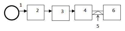 | Figure 1. Components for Fiber Daylighting |
2.2. Photovoltaic Cell (PVC) Power System Components
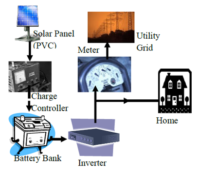
- A solar cell, or photovoltaic cell (PV), is a device that converts light into electric current using the photovoltaic effect. Solar cells produce direct current (DC) power which fluctuates with the sunlight's intensity. For practical use this usually requires conversion to certain desired voltages or alternating current (AC), through the use of inverters. Multiple solar cells are connected inside modules, which are wired together to form arrays, then tied to an inverter, which produces power at the desired voltage, and for AC, the desired frequency/phase.The main components for solar power system, as shown in Figure 2, include:1. Light source2. Solar Panels (PVC)3. Battery Banks4. Inverter5. Meter
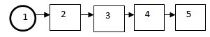 | Figure 2. Components for Solar power system |
2.3. Sun Tracking Mechanism and Solar Collector
- Proper operation of a passive or hybrid solar lighting system requires direct sunlight focused into the end of an optical fiber or solar panel, a task made difficult by the sun’s constantly changing position in the sky. In order to provide consistent light levels solar collectors employ tracking mechanisms to maintain constant alignment with the sun while mirrors or lenses reflect or refract light into a group of optical fibers. Tracking systems have been developed with the goals of maintaining precise alignment with the sun and maximizing operational hours.Maintaining proper collector alignment with the sun requires a mechanical tracking system capable of tracking both vertically and horizontally, relative to the earth. Two-axis tracking (Figure 3) designs contain one actuator to rotate the device around a vertical axis perpendicular to the earth, controlling the ‘azimuth’ angle (measured from due south), as well as an actuator to adjust the collector’s angle of tilt measured from the horizon known as the ‘altitude’ or ‘zenith’ angle.
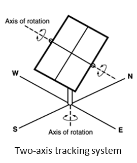 | Figure 3. Two axis tracking system |
2.4. Distribution System- Optic Fiber
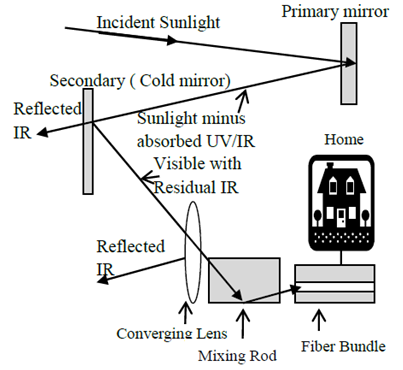
- Optical fibers are light-guides channels along which electromagnetic radiation of optical frequency can be conducted efficiently. In its most basic form an optical fiber is simply a core of dielectric material having a refractive index greater than that of the surrounding cladding material, resulting in total internal reflection of light entering the fiber’s end. The transparent cladding material is used to improve transmission efficiency by capturing any light scattered out of the fiber core by imperfections in the material or other factors.An optical fiber is a light guide governed by Snell’s Law, which defines the passage from a medium of refractive index n1 to a medium of refractive index n2 by a light ray having an angle of incidence θ1, as shown in Figure 4.
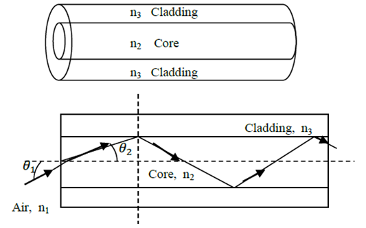 | Figure 4. Structure of Fiber and refraction of light |
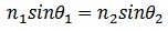 where
where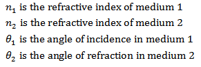 Snell’s law is used to determine the direction of light rays through refractive media with varying indices of refraction. The indices of refraction of the media, labeled n1, n2 etc, are used to represent the factor by which a light ray's speed decreases when traveling through a refractive medium, such as glass or water, as opposed to its velocity in a vacuum. Assuming that n1>n2, the angle of refraction is always greater than the angle of incidence (θ2 >θ1) and tend to become 90° when the angle of incidence is less than 90°. Therefore, for angles of incidence greater than this critical value the light is reflected with high efficiency. The value of this limiting angle (ϕ) is expressed as
 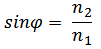 The spectrum of light transmitted by fibers is similar to that of nature light. With 98,000 lux of sunlight incident on the sun collector, each fiber transmits luminous flux of 1630 lumen over a distance of 15 m. This light disperses with an emission angle of 58° from the fiber end; placed at a height of 2 m it will illuminate the floor below with 420 lux [8].
3. Proposed System Implementation
- A hybrid system is proposed in this work, whereby a solar power (PVC) system is installed along side an optic fibre daylighting system. In this arrangement sensor switches on an ordinary electric light which is produced by the solar power system, if it gets too dark (and switches off again automatically when daylight levels increase again).
 | Figure 5. Schematic representation of the optical path that light travels in the Fiber Optic Lighting System |
 | Figure 6. Schematic representation of the Solar Power (PVC) Lighting System |
3.1. Computation of Illumination Efficiency
- The higher the angle of incidence
 , the lower is the power [9, 10]. In this work, calculation of the extracted energy in case of using tracking collectors is carried out by assuming that the maximum radiation intensity I = 1100Wm2 is falling on the area which is oriented perpendicularly to the direction of radiation. Taking the day length T = 12 h = 43,200, intensity of the tracking collector which is always optimally oriented facing the sun is compared to that of a fixed collector which is oriented perpendicularly to the direction of radiation only at noon. The collector area is marked as S0.
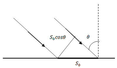 | Figure 7. Sun ray striking the surface of a collector |
 , where
  is changing in the interval (-π/2, +π/2) during the day. The angular velocity of the sun moving cross the sky is v = 2π/T = 7.27 *10-5 rad/s and the differential of the falling energy is
 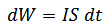 Neglecting the atmosphere influence, the energy per unit area is calculated for the whole day [11, 12]:
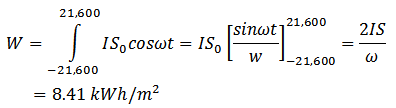 For a tracking collector, by neglecting the atmosphere influence, the energy per unit area for the whole day is
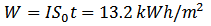 Comparing the equations above, 57% more energy is calculated for the latter case. The Solar energy that reaches the earth is given by; E = 0.58 * 3.6 * 10-9 * SπNr2whereS = Solar Constant – 1369 Watts/meter2N = No of hours r = Earth Radius = 6371KmAs for the transmission loss, in the optic fibre system it consists of three parts which are intrinsic loss, loss on end faces of fibers and loss led by bend. Among them, the intrinsic loss is a constant while loss on face is a large variation, determined by roughness. For the solar power system, losses are due to cable materials and conversion associated with the PVC generation of DC voltage and the inverter action.
3.2. Measured Results and System Efficiency
- Illuminance or light level is the amount of light energy reaching a given point on a defined surface area. Illuminance is measured by luxmeter, which is a handy instrument with a sensor for light detection. The measured illiminance is directly displayed in lux (lx). In this work the Konica Minolta T-10A Iluminance Meter was used for measuring the illuminance from the solar power and the optic daylighting systems, while the Matlab/Simulink was used to generate and simulate the efficiency and performance of both the optic fibre and power cable systems.Figure 8 shows the output power of the two systems for the same input power. It is evident that the optic fibre system has a better loss factor than the electric cable, hence a larger output power in the optic fibre than the electric cable for the same input power.
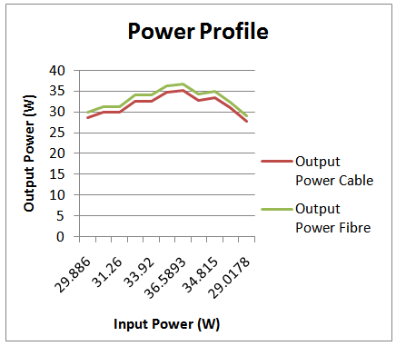 | Figure 8. Power Profile |
 = 95.75%η(FOD) = (33.0123 / 33.0374) * 100%
 = 99.92%According to the measured readings the efficiency of the Fiber Optic Daylighting with dual axis tracker is found to be 99.92% whereas the efficiency of the Electrical cable with dual axis tracker is 95.75%.Similarly, the measured illumination of the two systems, for the same output power, is shown in Figure 8. The result shows a better performance in optic fibre, of almost 4 times, than the electric cable.
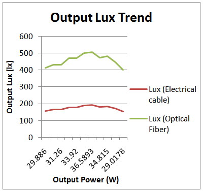 | Figure 9. Measured Optic Fiber and Artificial light illumination |
4. Conclusions
- From the graphs in Figures 8 and 9, the proposed Fiber Optic Daylighting system with a dual axis solar tracker, which is capable of tracking the sun throughout the year, provides higher output power and better Lux (Illumination). As electricity prices continue to increase and concerns about climate change drive construction to be more sustainable, innovative technologies will emerge to further improve efficiency and reduce consumption. Fiber optic daylighting systems represent the most effective method of bringing direct sunlight inside while maintaining the level of control desired by occupants and simultaneously mitigating the variability, glare, intensity, distribution and thermal comfort problems of traditional daylighting strategies. Transmission of sunlight through optical fibers maintains the natural frequencies and wavelengths of visible natural light while attenuating the infrared and ultraviolet components, eliminating the space heat gain and thermal comfort problems encountered in conventional daylighting design. The system can also be extended to other applications in future as its potential is enormous. In addition, worker productivity and health implications of natural lighting daylight harvesting with a fiber optic system represents the most efficient means of utilizing solar energy to reduce electrical consumption while enhancing indoor lighting quality. This technology expands the range of daylighting further into the building core, allowing designers to improve lighting quality across a greater floor area while displacing larger quantities of electric light without affecting space layout or mechanical loads.