-
Paper Information
- Paper Submission
-
Journal Information
- About This Journal
- Editorial Board
- Current Issue
- Archive
- Author Guidelines
- Contact Us
International Journal of Energy Engineering
p-ISSN: 2163-1891 e-ISSN: 2163-1905
2014; 4(2): 32-43
doi:10.5923/j.ijee.20140402.03
Experimental Studying of Improving the Thermal Performance of the Integrated Collector Storage Solar System by Plate Fins
 Abstract
 Reference
 Full-Text PDF
 Full-text HTML
Abdullah H. M. AlEssa , Nabeel S. Gharaibeh
AlBalqa Applied University, AlHusn University College, AlHusn, Irbid, JORDAN, P.O. Box 50
Correspondence to: Abdullah H. M. AlEssa , AlBalqa Applied University, AlHusn University College, AlHusn, Irbid, JORDAN, P.O. Box 50.
| Email: |  |
Copyright © 2014 Scientific & Academic Publishing. All Rights Reserved.
The integral collector storage (ICS) solar system is one of the promising solar system due to its attractive features such as lower initial cost, minimal operation cost as well as its immunity against the problems of freezing and overheating. The long-term performance of the conventional ICS system is less than that of the other conventional solar systems as the flat plate collector. To improve the CICS system performance, an array of plate fins is fixed in the system storage tank. The new system is referred to as NICS system. The NICS system gives a solution of increasing the CICS system performance. Its collection efficiency is better than that of the CICS system. The NICS system showed a better long-term performance under noon and evening load profiles.
Keywords: Solar water heater, Integral collector storage, Fins, Thermal performance, Stagnation collection efficiency, Water withdrawal profile
Cite this paper: Abdullah H. M. AlEssa , Nabeel S. Gharaibeh , Experimental Studying of Improving the Thermal Performance of the Integrated Collector Storage Solar System by Plate Fins, International Journal of Energy Engineering, Vol. 4 No. 2, 2014, pp. 32-43. doi: 10.5923/j.ijee.20140402.03.
Article Outline
1. Introduction
- Energy in its different forms has a great importance in the human's life. It is needed in domestic, commercial as well as industrial applications. Lately the problem of obtaining energy from its conventional sources like oil and coal have become expensive, especially for those countries that have no natural resources, due to the escalating price and the depletion of oil resources [1]. As a result of the above problems people began looking for energy from resources like wind, solar, and other renewable energy forms. In the present, solar energy is the most attractive alternative energy source for the future due to its availability and cleanliness [1, 2]. Solar water heating system proves to be an effective technology for converting solar energy into thermal energy. So the solar water heaters play a vital role in domestic as well as in industrial sector due to its ease of operation and simple maintenance. The solar energy collector is the central component of any solar water heating system. The characteristics of solar systems are based on the absorber plate and its design, selective coatings, thermal insulation, tilt angle of the collector [3]. The solar water heater is one of the fastest growing technologies in the renewable energy sector. Most solar water heater designs can be divided into three main types which are, the forced circulation (active systems), natural convection (thermosyphon or passive systems) and the integrated collector-storage systems [4]. Domestic water heating is one of the most successful applications of solar energy. Flat plate collectors are commonly employed in such systems. They are well developed and high efficiencies are attained. The water heating systems using flat plate collector require the use of a separate heat storage system (separate vessel or tank). In the thermosyphon system, the hot water tank is placed above the collector in a closed loop with the collector. The separate collector storage tank is bulky and doesn't fit on most of the modern inclined roofs or on multi- story buildings [5]. The integrated collector storage (ICS) solar water heater is simple in design and operation as its cost is lower than that of other systems. It operates with no moving parts (passive system) and it has a large thermal mass of working fluid preventing the freezing and the overheating problems in many conditions [4, 6]. In the ICS system the collector acts as hot water storage tank as well as a collector [5]. The conventional integrated collector-storage (ICS) solar water heaters belong in the category of direct heating solar systems (no heat exchanger). Those systems have reduced cost, compared to conventional flat plate thermosiphonic ones, because they integrate collector and heat storage tank in a compound construction. Moreover, they are considered to be more aesthetic [7]. The ICS developed from early systems comprised simply of a simple black tank placed in the sun. As it combined collection and storage function then it suffers substantial heat losses to ambient, especially at night-time and non collection periods. To be viable economically, the system has evolved to incorporate new and novel methods of maximizing solar radiation collection whilst minimizing thermal loss. Advances in ICS vessel design have included glazing system, methods of insulation, reflector configurations, use of evacuation, internal and external baffles and phase change materials. So the development of the ICS seeks to enhance collection of insolation and at the same time reduce heat losses [8, 9, 10, 11, 12]. The conventional form of the ICS system has lower long-term performance than that of the flat-plate. Tiedemann [13], compared the ICS systems with the conventional active water heating systems that uses flat-plat collectors. The experimental results indicated that the ICS systems provide (72-75%) of the flat-plat collectors output and its overall efficiency is about (72%) of that of the flat-plat collector systems. The long-term performance of the ICS system is affected by many parameters like the geometric design of the storage tank, the optical cover system design, the insulation system design. Garg and Rani, [14], studied the effect of the storage tank geometric design on the conventional form of the ICS system Performance. the storage depth was varied between (0.025 and 0.2 m). The shallow depth was found to result in the maximum daily temperature rise in the storage temperature however, the same depth results in the maximum temperature reduction during the no solar insolation periods as night. The minimum rise in the water temperature of the storage tank occurs in the case of 0.2 m for which the water temperature fall was very gradual as well. The case of 0.1 m depth shows water temperature rise of about 53℃ and it resulted the highest water temperature during early morning hours. The rise in temperature is lower for the of 0.15 and 0.2 m depths due to the large storage tank capacity, so the hot water of proper temperature requirement can't be obtained in these cases. In case of 0.025 m depth, the rise of temperature is very sharp but due to the high temperature difference during cooling hours the heat losses to the ambient will be very high hence the water temperature in the storage tank will sharply fall. Accordingly neither the 0.025 m depth nor 0.15 and 0.2 m depth can fulfill the hot water requirements, and the 0.1 m depth of the storage tank can be considered as the optimum which can supply hot water with a suitable temperature over most of the day [14]. The feasibility of using ICS system in domestic applications has been established. However, previous researches indicated that the main problem of the ICS system is its low performance. [14, 15, 16, 17]. It is the aim of this research to investigate the improvement of the ICS performance by using longitudinal plate fins in the storage tank of the ICS system. This will be done experimentally through designing and fabricating two solar systems, the conventional ICS (CICS) system without fins (shown in figure 1) and the new ICS (NICS) system with fins (shown in figure 2). The two systems are testing side by side under stagnation and different load profiles.
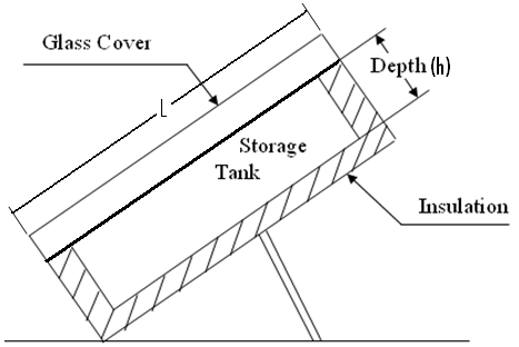 | Figure 1. Cross Section in the CICS Solar System |
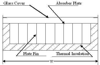 | Figure 2. Cross Section in the NICS Solar System with Longitudinal Plate Fins |
2. The Experimental Systems
- The constructed CICS system consists of the storage tank shown schematically in figure (1) which made of galvanized steel plates of thickness 0.0015 m. The absorbing surface which is one of the storage tank sides with dimensions of (L = 0.8, W = 0.6 m), was coated with black paint. The depth of the storage tank was chosen as (h1 = 0.1 m) which is the optimum depth for the ICS system [14]. The optical system was constructed with a single glass cover of (0.004 m) thickness located at a distance of (0.05 m) from the absorber plate. This distance was chosen as it is the optimum air gap between the glass cover and the absorber surface which gives the minimum convection heat losses with minimum shading. The inlet water enters the storage tank through a long pipe in the lower part of the tank with small holes perforated along it to ensure distributed feed water with minimum disturbances to maintain better stratification. The collector is insulated using (0.05 m) thick styroporboards covered by metal sheet with thickness of (0.0005 m) in case to carry on the insulation. The system was mounted on a steel frame facing south with an inclination (tilt) angle of (42°) which it is the latitude angle plus 10°. The NICS System shown in figure (2) is designed with the following criteria in mind:- The collector area, the absorbing surface coating, the optical system, the storage tank volume, the insulation, orientation, inclination angle of the NICS are the same as those of the CICS system. According to the previous criteria, the NICS system depth is (h2 = 0.102 m). This due to the fins volume and to fill the storage tanks with the same volume of water. The two systems are provided with a delivery opening at the top of the storage tanks, and a supply opening at the bottom of the system. The two systems were provided with two cocks fitted at the delivery openings to control the water withdrawal mass flow rate. The systems were installed on an open area avoiding shading and they are supplied by fresh water from a common reservoir mounted at a suitable height over them and plumped with main water supply. The two systems were exposed to the same conditions of solar insolation and ambient temperature.
3. The Measurement Systems
- The two systems had been provided with a number of copper- constantan thermocouple temperature sensors which were distributed in selected locations that were believed to yield the maximum information about their performance. The thermocouple sensors and their extension wires were fitted in plastic pipes to insulate them from water. Each system is provided with five thermocouple sensors as shown in figure (3). The storage tanks are divided into five nodes for each system and at the center of each one a thermocouple sensor is located. Temperature readings are obtained using a digital electronic potentiometer which was calibrated against mercury in glass thermometer. The calibration results are shown in figure (4).
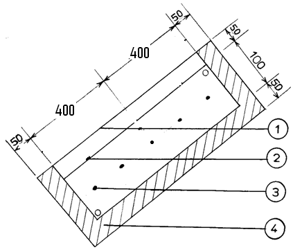 | Figure (3). Cross Section of the ICS System shows the thermocouple Sensors Locations. (1- Glass Cover, 2- Absorber Surface, 3- Thermocouple Sensor, 4-Insulation, Dimensions in mm.) |
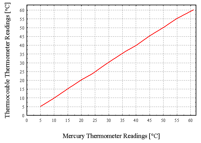 | Figure (4). Electronic Potentiometer Calibration Results |
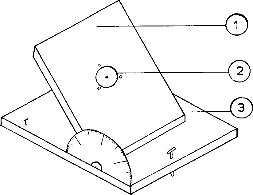 | Figure (5). The Pyronomter holding base (1- Rotating Plate, 2- The Pyronomter, 3- Base) |
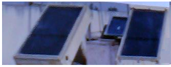 | Figure (6). Photograph of the two system |
4. The Experimental Schedule
- Three different experiments were carried out through winter season. Their general object was to investigate and compare the long-term performance of the two systems. The experiments are :-
4.1. The Stagnation Test Experiment
- The stagnation experiment was carried out to investigate and compare the two systems performance without water withdrawal. The experimental measurements were used to compute and compare the two systems mean temperatures, collection efficiency, collected energy. The experiment was carried out over five consecutive days. The data of temperature readings were taken every hour from 7:00 a.m. until 5:00 p.m.
4.2. Water Withdrawal Experiment
- Water withdrawal experiments are designed following the ASHRAE load profile [18]. According to this load profile, water was drawn in three equal batches at constant rates over the hours (7:00-8:00 a.m.), (12:00-1:00 p.m.) and (5:00-6:00 p.m.). The daily mass flow rates which it tested is 48 kg/ day related to the tank turnover of 1. That is 16 kg for each withdrawal of the three withdrawals during a day.
5. Experimental Data Analysis
- The procedures used to reduce the collected data to a form that is useful in comparing the two systems is described. The mean temperatures and the efficiencies of the two systems will be calculated as shown below.
5.1. Mean Temperature Calculations
- Mean temperatures of the CICS system is (Tm1) and for the NICS system is (Tm2). To compute these mean temperatures, the two systems are divided into a five nodes with a temperature sensor located at the center of each one. The mean temperature can be calculated from :-
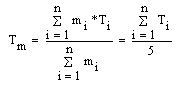 | (1) |
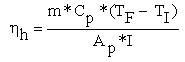
5.2. Efficiency Calculations
- Solar system performance can be expressed using the efficiency. The solar system efficiency is simply the ratio of the collection or delivered energy to the total incoming solar energy. The instantaneous efficiency as a short-term performance is mathematically defined as :-
 | (2) |
 | (3) |
 | (4) |
 | (5) |
 | (6) |
6. Results and Discussion
- In this section the results obtained from all experiments explained previously will be presented and discussed. Since both the CICS system storage tank and that of the NICS are designed to have the same storage capacity and subjected to the same solar conditions, the comparisons can be made based on the temperatures, mean temperatures as well as the hourly and daily collection efficiency.
6.1. The Stagnation Test Results
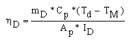
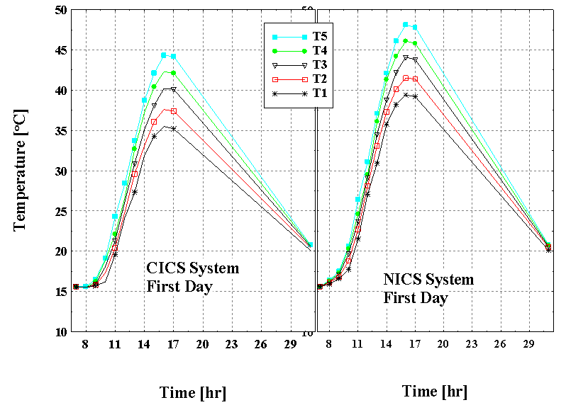
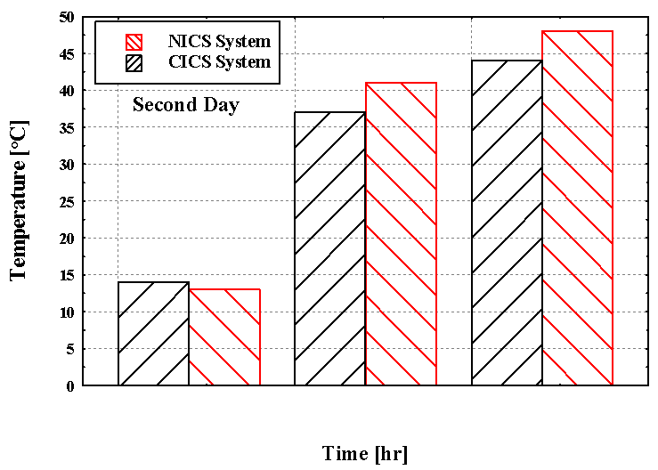
- The stagnation test was carried out over five consecutive days during March in a region of (Latitude 32°N, Longitude 36 °E). The temperatures of the CICS system nodes and that of the NICS (T1, T2, T3, T4, T5) are presented in fig. (7). This figure shows higher temperatures of the NICS system than that of the CICS system with the magnitude of about 2.5℃.The temperatures comparison of the other four days of the stagnation experiment is shown in figures (8) and (9). Again these figures show higher temperatures of the NICS system than that of the CICS system.
 | Figure (7). The temperature distribution of the two systems for the first day |
 | Figure (8). The temperature distribution of the CICS system for the other four days |
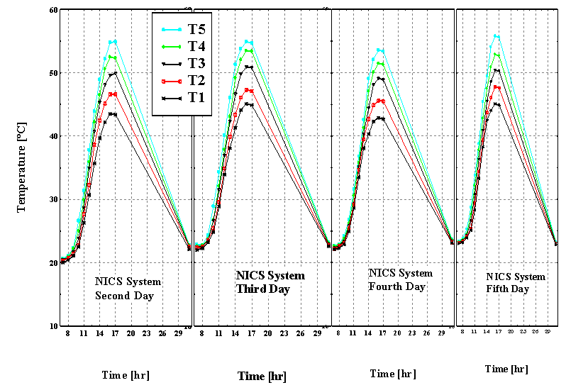 | Figure (9). The temperature distribution of the NICS system for the other four days |
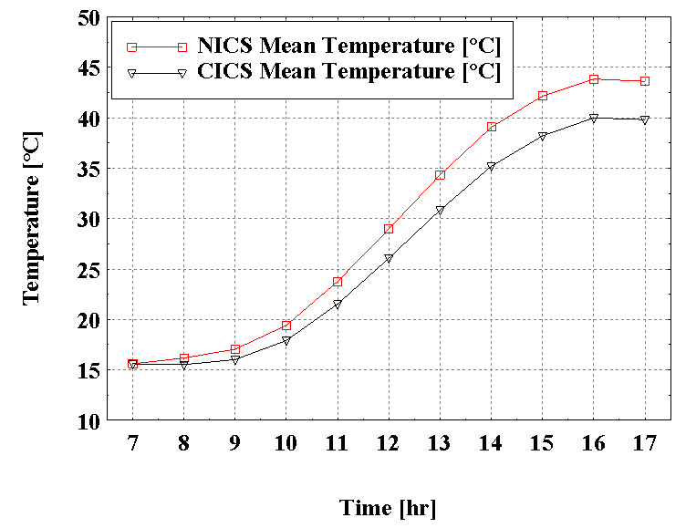 | Figure (10). The mean temperature variation of the two systems for the first day of the stagnation test |
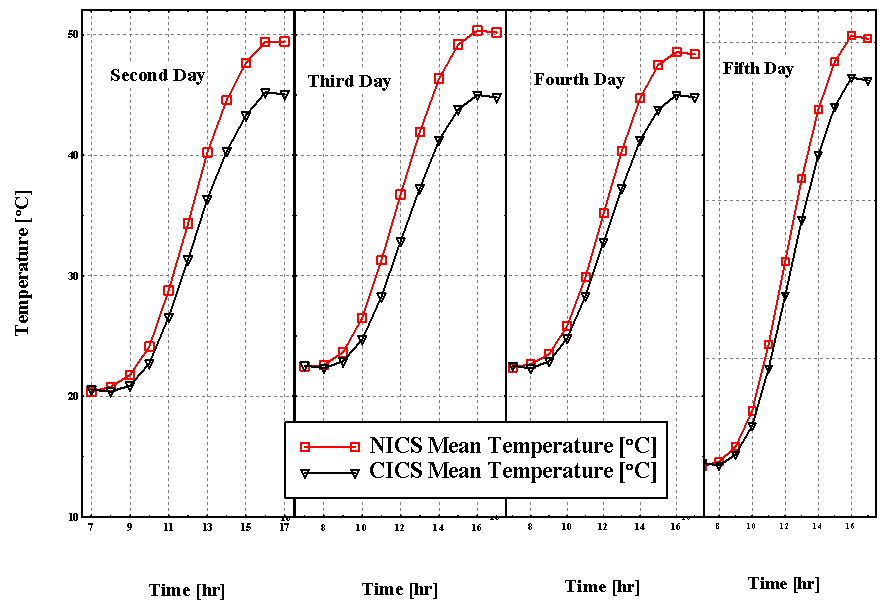 | Figure (11). The mean temperature variation of the two systems for the other four days of the stagnation test |
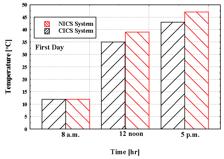
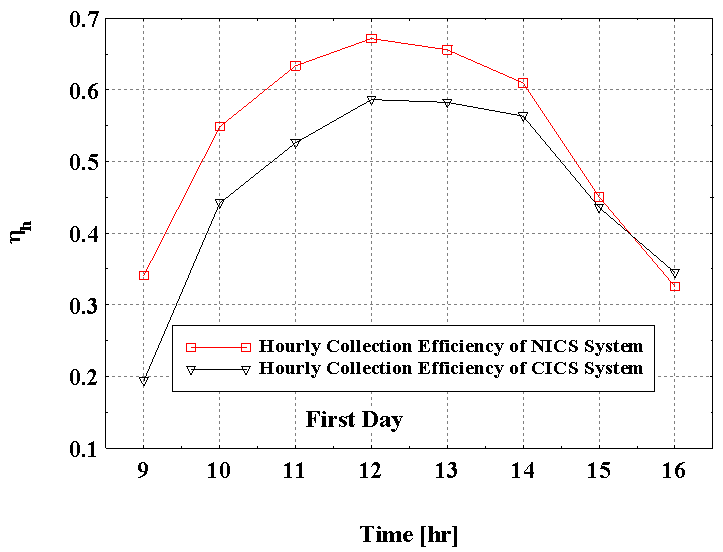 | Figure (12). The hourly collection efficiency of the two systems and the integral hourly solar radiation (kw. hr/ m2) for the first day of the stagnation test |
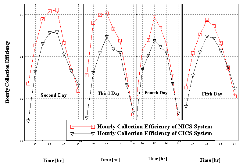 | Figure (13). The hourly collection efficiency of the two systems for the four other days of the stagnation test |
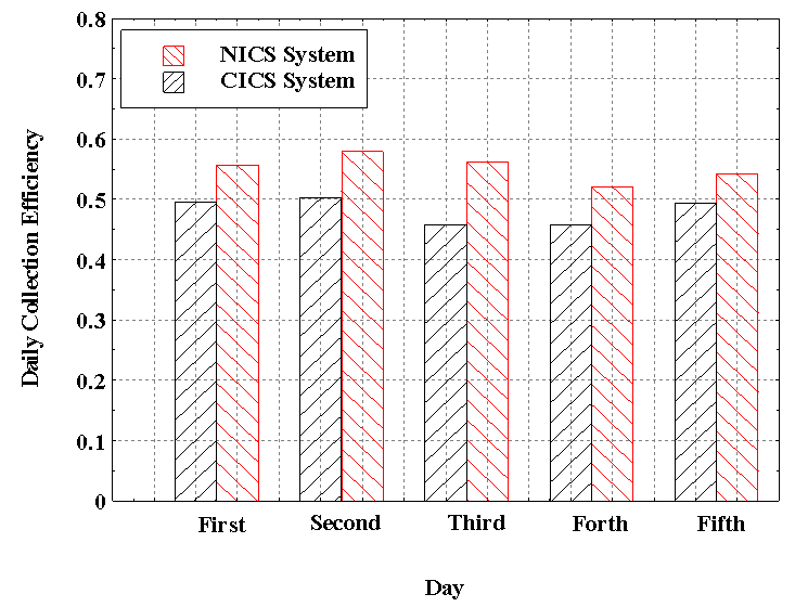 | Figure (14). The daily collection efficiency of the two systems for the five days of the stagnation test |
6.2. Mass Flow Rate Withdrawal Effect on the Performance of the Two Systems
- In this experiment, the daily ASHRAE load profile [21], has been adopted as mentioned in section (4. 2). During this experiment (16) Kg of water has been withdrawn from each system in three times of the daily ASHRAE load profile. Figures (15), (16) and (17) show the delivery temperatures of the two systems for the three days over which the experiment was conducted.
 | Figures (15). The delivery temperatures of the two systems for the first day over which the withdrawal experiment was conducted |
 | Figures (16). The delivery temperatures of the two systems for the second day over which the withdrawal experiment was conducted |
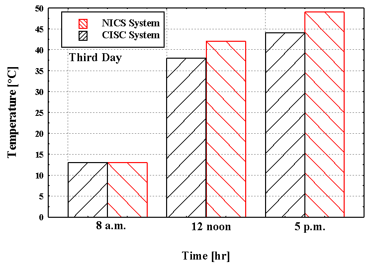 | Figures (17). The delivery temperatures of the two systems for the second day over which the withdrawal experiment was conducted |
7. Conclusions
- This work presented a testing of two forms of integrated collector storage system. The first is the traditional rectangular one (CICS) based on the optimum dimensions given in the literature and the second is (NICS) which is provided by internal plate fins. The NICS is investigated as a possible solution to increase the ICS Performance.Different test carried out and the main conclusions observed are:-1- The NICS system with its plate fins gives an acceptable solution to increase ICS system performance. 2- The collection efficiency of the NICS system is better than that of the CICS system.3- For the ASHRE noon and evening load profiles, the water withdrawal delivery temperatures of the NICS system is higher than that of the CICS system.4- The NICS system showed a better long-term performance under noon and evening load profiles.
Nomenclature
- Ap:- The absorber plate area [m2]Cp:- Specific heat capacity of water [J/Kg. K]CICS:- Conventional integral collector storage. G:- The instantaneous incoming solar energy [J/ m2. Sec]h1:- The storage tank depth of the CICS system [m].h2:- The storage tank depth of the NICS system [m].I:- The hourly incoming solar energy [J/ m2]Ih:- The integral hourly solar radiation measured by the Pyronomter each hour [kw. hr/ m2]ID:- The integral daily solar radiation measured by the Pyronomter each day [kw. hr/ m2]L:- The storage tank length [m].m:- Mass of water [Kg]NICS:- New integral collector storageQf:- Instantaneous collection or delivered energy [J/ Sec]Qhf:- Collection energy per hour [J/ hr]QDf:- Collection energy per day [J/ Day]Tm1:- Mean temperature of the conventional ICS system [℃].Tm2:- Mean temperature of the new ICS system [℃].Td:- Delivery temperature [℃]W:- The storage tank width [m].
Greek Letters
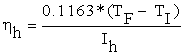
- ηD:- Daily efficiencyηh:- Hourly efficiency
Subscripts and Superscripts
- D:- Daily. d:- Delivery.F:- Final.h:- Hourly.I:- Initial.i:- The node numberm:- Mean temperature