Attar M. Z.
Dept. Ag. Eng., Ain-Shams U., Cairo, Misr (Egypt), P.O. Box 68, Hadayek Shoubra, Cairo 1124, Egypt
Correspondence to: Attar M. Z., Dept. Ag. Eng., Ain-Shams U., Cairo, Misr (Egypt), P.O. Box 68, Hadayek Shoubra, Cairo 1124, Egypt.
| Email: |  |
Copyright © 2012 Scientific & Academic Publishing. All Rights Reserved.
Abstract
This paper focuses on achieving simplest and effective design for an electronic active tracking system. It was found that the sensor could be enhanced by using four phototransistors longitudinally shaded by 50 % of their area with black paint barrier to sense solar ray inclination angle with accuracy of 1.2°. The tracking circuit was also enhanced to be self-adjusting at different light intensities. The circuit can detect sun position with intensity of 6.3 lux enabling the system to work at dusty and cloudy environment. The cost of the solar tracker was reduced by simplifying its design and fabrication process.
Keywords:
Solar tracking, Electronic tracking, Active solar tracker
Cite this paper: Attar M. Z., Enhancement of an Electronic Solar Tracking System, International Journal of Energy Engineering, Vol. 4 No. 1, 2014, pp. 5-9. doi: 10.5923/j.ijee.20140401.02.
1. Introduction
A solar tracking system is a method that forces a solar power-harvesting unit to operate at its maximum power under varied environmental conditions. The construction of a mechanism to follow the path of the sun is not a recent issue. An attempt in Chile was completely mechanical, done by Finster in 1962. Later, a researcher team presented a mechanism with an automatic electronic control[8]. Cost reductions of the order of 19% for the tracking system and 48% for the concentrating system were achieved when compared with the fixed system[3]. Commercial solar cells convert solar energy into electricity at a relatively low efficiency, between 5% and 50%. Most of the absorbed energy, from 80% to 95%, is dumped to the surroundings again[12].The energy from the sun can serve many purposes; one of them is to generate electricity through PV panel. PV can meet electricity demand at remote areas where there is no connection to the electricity grid, households, powering water pumps, refrigerators, and for power generators. Using electronic tracking system increases the efficiency of water solar collector, solar dryers of agricultural materials, maturing compost, shading animal buildings, and control the environment of the green houses.The aim of this work is to enhance the solar tracker sensitivity presented in Awady et al.[1] and to minimize the total cost of sensor fabrication, besides enhancing the driving circuit to be self-compensating and more sensitive to less changing in light intensity.
2. Materials and Methods
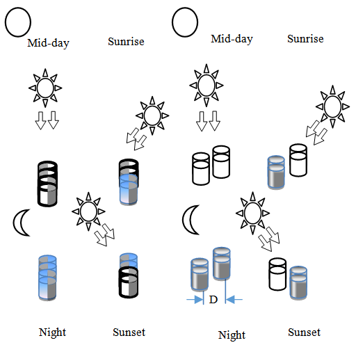 | Figure 1. Working theroy of solar tracingcircuit: (A) the sensing pair were separated by distance “D”, and (B) the sensors pair had a clear side in opposite direction to each |
Working theory: The solar tracking system consists of four sensing elements aligned with each other on the side facing the sun, fixed to the tracking axle, and one rear clear phototransistor of position restoration. Sensors alignment was considered to achieve balanced illumination on all sensing elements when the solar rays fall in right angle on its surface. Two arrangements of sensing elements were tested as shown in Figure 1. The four phototransistors are arrangedinto two pairs. In the first arrangement, the sensing pair were separated by distance (D), Figure 1-A. In the second arrangement, each pair had a clear side in opposite direction to the second pair. While other sides of the sensing elements were blocked from solar rays by a black coat, Figure 1-B. The sensing elements produce a control signal in case of detection of inclined solar rays through the signal amplifier and comparison circuit. The solar tracker sensing elementswere selected among light dependent resistor (LDR), infrared, and phototransistor (Figure 2).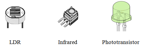 | Figure 2. The solar tracker sensing elements |
Four cases of sensor alignment (Figure 1-A) were investigated for different D-distances as illustrated in Figure 3.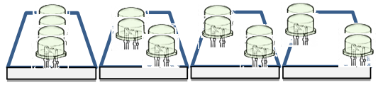 | Figure 3. Photo-sensors alignment |
Sensing alignment is illustrated in Figure 1-B. The surface area for the sensing elements was blocked with black coat for incoming solar rays by 0, 16.7, 33.3, and 50% from total sensing element surface area as shown in Figure 4.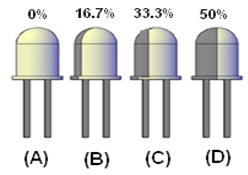 | Figure 4. Cases of shading (A) 0% (clear),(B)16.7%, (C) 33.3%, and (D) 50% shading |
Solar tracker system was poweredby potential sources of 6,9,12, and 15 volts to determine its effect on the total performance and accuracy of the tracker.A Luxmeter “Extech instruments”, model 407026 was used to measure the intensity of light for the experimental process. Light source of 3350-lux incandescent lamp matches that of a black body at a color temperature of 2850 °K was used to evaluate the sensing element performance at different light intensities (Figure 5). This type of light source agrees to standard γ (gamma) according to Equation 1[10]. 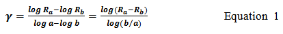
 | Figure 5. Phototransistor resistance curve, and γ (gamma) calculations, Sensor assembly |
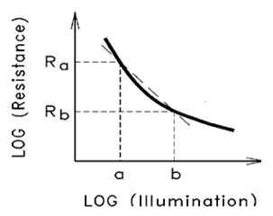
The solar tracking sensor consists of (1) four frontal (facing to the sun) sensing elements, each vertically shaded by 50% of its surface with black paint, aligned linearly in opposite shading direction to each other, and (2) one clear rear (opposite to the sunrays) sensing element for morning position restoration, Figure 6.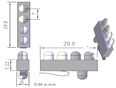 | Figure 6. Solar tracker sensing elements alignment for the experiment set |
Driving circuit description: Four phototransistors were used to sense the falling light from the sun. Phototransistors were configured as shown in Figure 7 to maximize the output voltage and to get measurement linearity free of error for constant voltage configurations. Solar tracking driving circuit consists of dual transistor pairs of BD135 (NPN transistor), and BD136 (PNP transistor) for amplifying measured signal.The solar tracker signal current was amplified in two stages by the BD135 according to the Equation2. The overall current gain is equal to the two individual transistors andwas calculated according to Equation (3). A high current gain needs a tiny base current (low solar rays intensity) to switch-on sensor. A protection diode was connected across the load to protect the transistor from damage when load is switched off.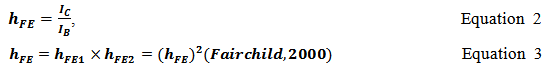 where,
  : Transistor collector current,
  : Transistor base current
  : Transistor gain,
  are the gains for the individual transistors.
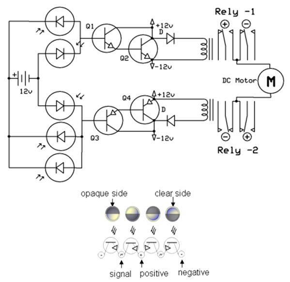 | Figure 7. Tracking circuit diagram, and working cases |
For the BD135, and BD136 transistors, the total gain is  ≈ 62500. Figure 8 illustrates the final assembly of the solar tracking driving circuit.
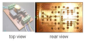 | Figure 8. Assembly of the solar tracking circuit |
3. Results
Light Dependent Resistance (LDR), Infra-Red (IR), and phototransistor light detection sensors were examined against illumination performance as shown in Figure 9.For tracking sun, γ value of optical detector curves with shallow slopes will be better suited. A phototransistor was chosen for its high performance and low price, Table 1. | Table 1. γ value for different types of optical detection units |
| | | γ | | IR | -1.015 | | LDR | -0.63 | | Phototransistor | -0.898 |
|
|
The circuit of sun tracker is on when sensor voltage difference equals or increases above 0.3 V, that is because at that level of electrical potential, the circuit transistors are switched on, when transistor’s emitter-collector junction is about 0.3 volts.Phototransistor vertical alignments according to spacing between pairs of phototransistors at 0,5,10, and 15mm spacing are illustrated in Figure 10. The Figure shows that the spacing between phototransistor pairs at 0 and 5mm has no effect of illumination received by the sensors and circuit is off all the time. Phototransistor spacing at 10, and 15 mm turned on the circuit at rays’ inclination angle of 32° and 14° respectively. The responses of phototransistor alignment refer to the nature of phototransistor efficiency for detecting light at different inclination angles. 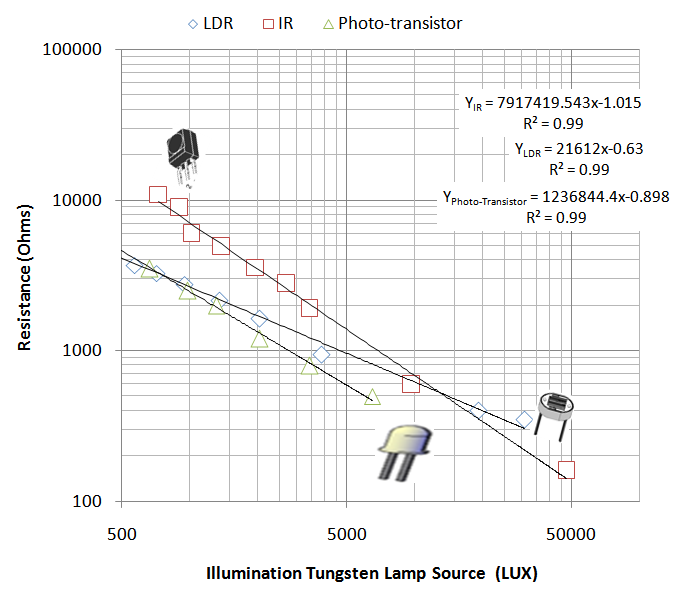 | Figure 9. Optical detection performance at different light intensities |
 | Figure 10. Solar tracking sensor alignment at different spacing between sensor pairs |
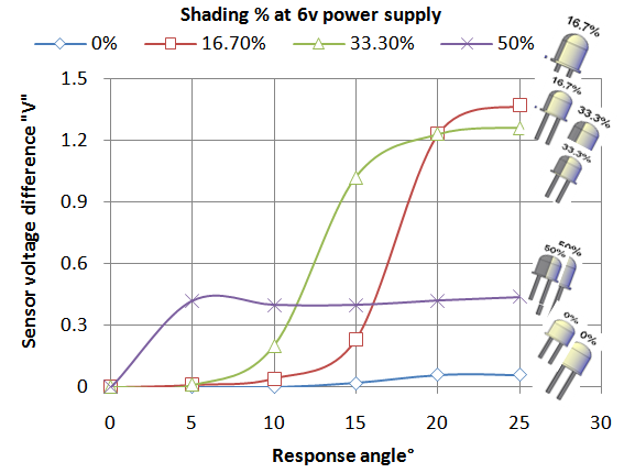 | Figure 11. Solar tracking: sensor performance with different shading levels |
At 0 and 5 mm sensor spacing, the effect of falling light at the phototransistor has same effect on all phototransistor, to make no voltage difference for the circuit to activate. In phototransistors spacing of 10 mm alignment, the light affects differently at the phototransistor pairs, so a voltage difference is present, and circuit is on when voltage difference is 0.3volts at 32° light inclination angle. At spacing of 15 mm between phototransistor pairs, the circuit responds at 14° of light inclination angle.When circuit was examined for alignment as in Figure1-B, results showed that the transparentphototransistor andpartial transparent phototransistor(16.7% surface coated with black) were not able to detect the solar direction. In case of sensor coated by 33.3% of its surface with black, the response angle was 12°, and was better in the shading of 50% (phototransistor with half rays blocking coat) to respond at 3°. That suits case of tracking the sunby solar concentrators which are too sensitive to the change of inclination angle of solar rays, Figure 11.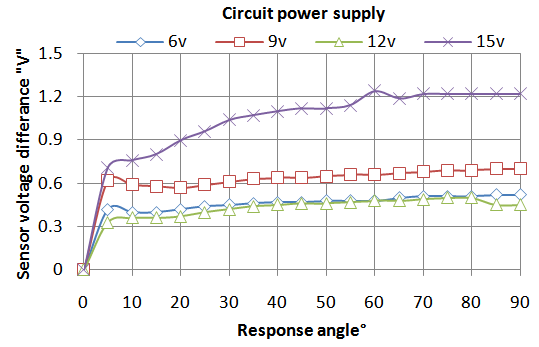 | Figure 12. Solar tracking: circuit performance with different power supplies |
Solar tracking system was affected by its power supply. Performance analysis under varying electrical potential was investigated by using 6,9,12, and 15 V. The circuit responds to potential of 15V at 3° as well as 12V. The response angle increases slightly with decreasing potential to ninevolts to be at 4°. Furthermore, the potential of 6 volts forces the circuit to respond on light inclination angle of 5° at the same intensity of light (3320 lux), as shown in Figure 12.Solar tracking circuit was also examined against light intensity level. Four light intensities were used to measure sensor sensitivity for 2100, 3120, 3350, and 18600 lux (Figure 13). It was found that light intensity affects the performance of the tracker sensor. At high intensity, sensor responds to light at 12.5° inclination angle. Sensor sensitivity increased with decreasing light intensity to respond at 3° rays inclination angle for intensity of 3350 lux. Sensor maximum sensitivity was around 1.25° for light intensity of 3120 lux and 2100 lux. The minimum measured light intensity was found to drive the circuit to work at 6.3 lux. That enables the sensor to work even when covered by dirt (lack of maintenance) and cloudy weather.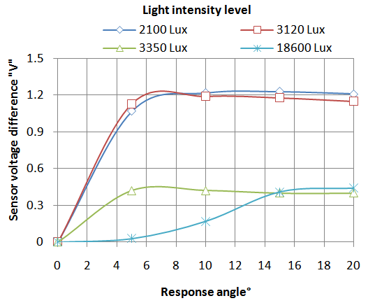 | Figure 13. Solar tracking: circuit under different light intensities |
4. Conclusions
Because of the nature of enhanced solar tracking circuit, no signal calibrations are required. The sensor has excellent performance and suits the parabolic concentrator of solar power harvesting unit when using a shaded phototransistor with black paint of 50% of its surface, and aligned linearly. The enhanced solar tracking system achieves maximum accuracy of detecting the sun position in the range of 1.25° to 12° according to the light intensity. The ease of sensor fabrication and low cost of phototransistor make it suitable for use in all applications needing the tracking of the sun.It is concluded that the proposed approach can be used as a robust and fast acting maximum power tracker. The circuit performs well at power supply of electrical potential of 6volts, so circuit can be powered form an AC or DC power source. The system is applicable as stand –alone in remote areas as the DC power source can be fed through chargeable batteries.Under cloudy conditions, when the sun is not visible or in dusty weather, the device can track at light intensity of 6 lux or 0.1% from the maximum intensity. It is very fast and causes no oscillation around the operating point.
References
| [1] | Awady, M.N.; and M.Z.; Attar, An Electronic Solar Tracking System, Acad. Sci. Tech. Patent No. 23899, 2007. |
| [2] | Alexandru; C., Comşi; M., and Alexandru; P., Dynamic Optimization of A 2-DOF Pseudo-Equatorial Tracking System in Product Design and Robotics Department, Centre “Product Design for Sust. Devel.”, Univ. “Transilvania” of Braşov.Poster Session C1:215, 2007. |
| [3] | Bione; J., Vilela; O., and Fraidenraich; N., Comparison of the performance of PV water pumping systems driven by fixed, tracking and V-trough generators, Solar Engergy, 76: 703-711, 2004. |
| [4] | Ecell; R., Determination for the optimum response angle of solar liquid flat plate collectors, (T. King Mongkut's University of Technology Thonburi, Producer), Retrieved from http://www.jgsee.kmutt.ac.th/exell/,2000. |
| [5] | Elmer; p., Optoelectronics, Retrieved 12 14, 2008, from http://optoelectronics.perkinelmer.com/content/manuals/gde_photocellselecting.pdf,2004. |
| [6] | Finster; C., “El Heliostato de la Universidad Santa Maria,” Scientia, 119: 5–20, 1962. |
| [7] | Fairchild; S.,. BD135/137/139 NPN Epitaxial Silicon Transistor. Retrieved 10, 27, 2008, from Fairchild Semiconductor International:http://www.fairchildsemi.com/ds/BD/BD135.pdf,2000. |
| [8] | Georgiev; A., Roth, P., and Olivares, A., Sun Following System Adjustment at the UTFSM.(www.elsevier.com/locate/enconman, Ed.) 45:1795-1806, 2004. |
| [9] | Panasonic, Phototransistors-PNA1801L (PN168)-datasheet, Retrieved from http://instruct1.cit.cornell.edu/courses/ee476/ FinalProjects/s2002/cmp28/PN168.pdf,2001. |
| [10] | Perkin Elmer, Perkin Elmer for the better, Retrieved from Perkin Elmer:http://optoelectronics.perkinelmer.com/StartPage.aspx,2004. |
| [11] | Rizk; J., & Chaiko, Y., Solar Tracking System: More Efficient Use of Solar Panels. Proc. of world Acad. Sc. Eng. and Tech. , 31:1307-6884, 2008. |
| [12] | Rosel; J., Vallverdu; X., Lechon; M., and Ibanez; M., Design and Simulation of a Low Concenterating Photovoltic/ Thermal System. Energy Conversion and Manag., 46:3034-3046, 2005. |
 Abstract
 Reference
 Full-Text PDF
 Full-text HTML