-
Paper Information
- Previous Paper
- Paper Submission
-
Journal Information
- About This Journal
- Editorial Board
- Current Issue
- Archive
- Author Guidelines
- Contact Us
International Journal of Energy Engineering
p-ISSN: 2163-1891 e-ISSN: 2163-1905
2013; 3(5): 272-277
doi:10.5923/j.ijee.20130305.06
The Effect of Flat Heater Inclination on the Heat Transfer Coefficient in Gas-Fluidized Beds
 Abstract
 Reference
 Full-Text PDF
 Full-text HTML
M. A. Al – Busoul1, H. A. Al-Tahaineh2
1Mechanical Engineering Department, Faculty of Engineering technology, Al-Balqa Applied University, Amman, Jordan
2Mechanical Engineering Department, Al-Huson University College, Al-Balqa Applied University, Irbid, Jordan
Correspondence to: H. A. Al-Tahaineh, Mechanical Engineering Department, Al-Huson University College, Al-Balqa Applied University, Irbid, Jordan.
| Email: |  |
Copyright © 2012 Scientific & Academic Publishing. All Rights Reserved.
In this paper the effect of the orientation of a flat heater on the heat transfer coefficient in a gas- solid fluidized bed was experimentally investigated. The effect of the rectangular heater and the gas flow was examined by changing the angle from 0 to 180, and its connection with the effect of the hydrodynamic parameters. The experimental results were conducted at ambient temperatures in a Plexiglas Coleman of 142 mm I.D. and the heater used was made of copper and electrically heated by a constant power of 6w. The heater position was at constant height in the column but its radial position was changed. Oil shale particles of different size were used as the solid phase in the fluidized bed. The velocity of air was changed in the range from 0.035 m/s to 1.8 m/s. The results obtained were discussed and compared with other previous studies. This study aids in gaining a better understanding of heat transfer mechanism which is sufficient to designing and operating the fluidized bed reactors properly.
Keywords: Fluidized Bed, Heat Transfer Coefficient, Orientation
Cite this paper: M. A. Al – Busoul, H. A. Al-Tahaineh, The Effect of Flat Heater Inclination on the Heat Transfer Coefficient in Gas-Fluidized Beds, International Journal of Energy Engineering, Vol. 3 No. 5, 2013, pp. 272-277. doi: 10.5923/j.ijee.20130305.06.
Article Outline
1. Introduction
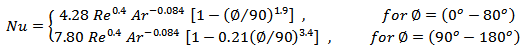
- The recent increase in the cost of energy, has added incentive to the development of efficient techniques for power generation by the use of available fossil fuels in Jordan. One of the most important fuels in Jordan is oil shale. An extensive work is going on to develop fluidized bed in which the combustion of solid fuels, coal and oil shale occurs because the fluidized bed combustion technology has many attractive features such as: relatively effective emission control, fuel flexibility, excellent solid- gas mixing, and temperature homogeneity[1-4]. However, further NOx and SOx reduction is still needed in order to have a more stringent emission limit.For proper design of fluidized bed reactors, it is sufficient to understand the mechanism of heat transfer and the effect of operating parameters on the heat transfer process. Several models have been proposed to explain the aforementioned heat transfer behavior, as was summed up by[5, 6]. Although there are still doubts about the procedure, many authors approximate the overall heat transfer coefficient for particle convention, gas convention and thermal radiation. A simple and reliable prediction of heat transfer analysis between fluidized bed and immersed surfaces. The correlations have been shown to give reasonable conditions. One of these empirical correlations was given by Al-Busoul[7]:
 | (1) |
 | (2) |
 | (3) |
 | (4) |
2. Experimental Apparatus and Procedure
- The experimental apparatus used in this study has been described previously[18]. It’s formed from a Plexiglas column 142mm I.D. and 1m in height. The specifications of the air supply system, instrumentation flow meters, pressure drop measurement and power supply and thermocouples have been described in a detail in a previous study[18].For the heat transfer measurement an electrical plate heater shown in fig 1 is used. The heater is formed from a copper plate of (12 cm2) in area. The minco electrical resistance used is (50Ω). This resistance is housed in a Teflon cover, which in the same time fasten the copper plate and limits the heat losses. A thermocouple was used to measure the surface temperature and another thermocouple was used to measure the bed temperature.The heating power was constant at (6 w). For different particle size oil shale were used as the fluidized bed. The properties of the oil shale particles are shown in table 1. The value of Umf found in the table was determined experimentally by using the following relation Δp = f (u).
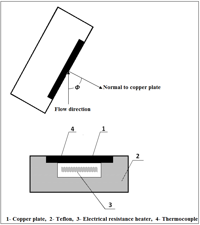 | Figure 1. Electrical heater |
 was calculated using the equation of Andersson[3]:
 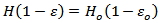 | (5) |
 is related to the density ratio as:
 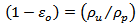 | (6) |
 | (7) |
3. Results and Discussion
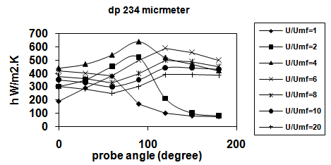
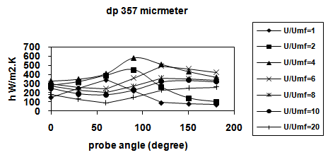
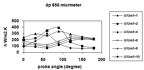
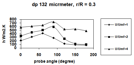
- Figures 2, 3, 4 and 5 show the variation of heat transfer coefficient with the angle of inclination of the heater surface from the direction of fluid flow, for various values of u/umf and r/R = 0. Each figure represents experiment results for certain particle size.
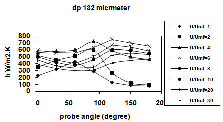 | Figure 2. The effect of heater angle on h at r/R=0 |
 | Figure 3. The effect of heater angle on h |
 | Figure 4. The effect of heater angle on h at r/R=0 |
 | Figure 5. The effect of heater angle on h at r/R=0 |
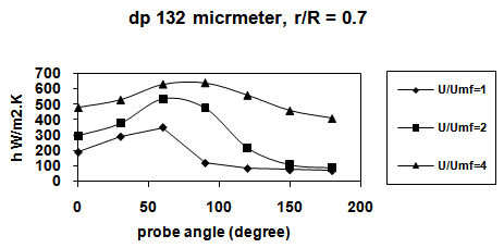
 | Figure 6. The variation of h with the probe angle for r/R=3 |
 | Figure 7. The variation of h with the probe angle for r/R=3 |
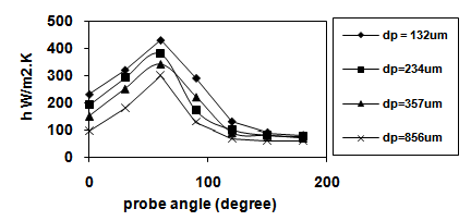 | Figure 8. Variation of h with probe angle at r/R=0 and U/Umf =1 |
- Figure 7 Shows the variation of h with near the wall at r/R= 0.7 for three different values of u/umf. For certain value of it could be seen that the angle at which, h increases rapidly is smaller near the wall than that at center of the bed. Owing to the difference of the intensity of the particle motion. In addition, h values at the center are higher than those values near the wall for the same reason. This agrees with the results found in[18, 21] but it is not in agreement with the results found in[20].The variation of h values with at u/umf =1 and r/R=0 for different particle sizes is shown in figure 8. It could be noting that as dp increase h decrease as demonstrate by many researchers.
4. Conclusions
- An experimental study has been performed to investigate the effect of the orientation of a flat heater on the heat transfer coefficient in a gas – solid fluidized bed. The effect of the flat heater and the gas flow were examined by changing the angle from 0o – 180o, the particle diameter, the gas velocity and the radial heater positions. The experimental results showed the following conclusions: 1- at u/umf = 1, hmax is the same for all particle sizes and occurs at = 60 .2- as u/umf increases from 1 to 4, corresponding to h max changes from 60 to 90 and the maximum occurs at 180o.3- at u/umf = 4, hmax occurs at 90, and increases with u/umf until it reaches 180 when u/um reaches 20-30.4- h values at the axis are higher than those values near the wall.5- as dp increase, u/umf corresponding to u/umf increase.Finally, it is recommended to conduct more research to find out the effect of different variables on the heat transfer coefficient in a gas- solid fluidized bed.
List of Symbols
- A : area of heat transfer surface (m2).Ar : Archimedes number.C : constant in correlation number (4).dp : average particle diameter mm .h : heat transfer coefficient w/m2.kH : fluidized bed height (m).Ho : static bed height (m).Nu : Nuselt number.Nucond : conductive component of particle Nuselt.Nuconv : convective component of particle Nuselt.Pr : Prandtl number.Q : heat transfer rate (w).Re : Reynolds number.Tb : bed temperature (k).Tw : wall temperature (k).U : fluid velocity.u/umf : fluid velocity at minimum fluidization m/s.ρp : density of solid particle (kg/m3).ρu : apparent density of solid (kg/m3). : Probe angle. 1-ε : concentration of solid particle in fluidized bed. 1-εo : concentration of particles in static bed.
References
| [1] | A.A. Khan, W. Jong, P.J. Jansens, H. Spliethoff, “Biomass combustion in fluidized bed boilers: Potential problems and remedies”, Fuel Process Technol. 90 (2009) 21-50. |
| [2] | B. Leckner, B. A. Andersson,” Characteristic features of heat transfer in circulating fluidized bed boilers”, Powder Technology Volume 70, Issue 3, June 1992, Pages 303–314 |
| [3] | B. Andersson, “Effects of bed particle size on heat transfer in circulating fluidized bed boilers”, Powder Technology, 87 (1996) 239-248. |
| [4] | Peng Sun, Shi'en Hui, , Zhenxing Gao, Qulan Zhou, Houzhang Tan, Qinxin Zhao, Tongmo Xu, “Experimental investigation on the combustion and heat transfer characteristics of wide size biomass co-firing in 0.2 MW circulating fluidized bed”, Applied Thermal Engineering Volume 52, Issue 2, 15 April 2013, Pages 284–292. |
| [5] | P. Basu, P.K. Nag, “Heat transfer to walls of a circulating fluidized bed furnace”, Chem. Eng. Sci. 51 (1996) 1-26. |
| [6] | L.R Glicksman, “Heat transfer in circulating fluidized bed”, Circulating Fluidized Beds, 1996, pp 261-311. |
| [7] | M. A. AL-Busoul, S. K. Abu-Ein, “Local heat transfer coefficients around a horizontal heated tube immersed in a gas fluidized bed”, Heat and Mass Transfer, April 2003, Volume 39, Issue 4, pp 355-358. |
| [8] | V.L. Ganzha, S.N. Upadhyay, S.C. Saxena, “A mechanistic theory for heat transfer between fluidized beds of large particles and immersed surfaces”, International Journal of Heat and Mass Transfer Volume 25, Issue 10, October 1982, Pages 1531–1540. |
| [9] | Afşin G., “Simulation of bed-to-wall heat transfer in circulating fluidized bed”, J. of Thermal Science and Technology, 28 (2008), 1, 9-16. |
| [10] | Vreedenberg. H.A, “Heat transfer between fluidized bed and vertically inserted tubes”, Journal of Applied Chemistry, Vol. 2, 1952, pp S26-S33. |
| [11] | Yasuo Kurosaki, Hiroshi Ishiguro, and Kiyoshi Takahasi, “Fluidization and heat transfer characteristics around a horizontal heated circular cylinder immersed in gas fluidized bed”. Int. j. heat mass transfer, Vol. 31(1988). No. 2 pp. 349-358. |
| [12] | Chandran JC, Chen and FW Staub, “Local heat transfer coefficient around horizontal tubes in fluidized bed”, trans. Am. Soc. mech. Engrs. Series c. heat transfer 102(1980), 152- 157. |
| [13] | Saxena SC, NS Grewal, JD, Gabor SS, Zabrodsky and D M Galershtein, “Heat transfer between a gas fluidized bed and immersed tubes”, advances in heat transfer (edited by T.F. Irvine. JR. and J.P. Hartentt) 14 (1979) pp- 149- 247, Academic press, New York. |
| [14] | Genetti R A, WE schmall, and E S Grimmett, “The effect of tubes in a fluidized bed”, A, I. Ch. E.SYMP. SER 67(1971) (116), 90-96. |
| [15] | CRETU J, YANG L AND S, C SAXENE, “Heat transfer to a single smooth vertical tube immersed in air fluidized bed”, letters in heat mass transfer 8(1981), 465-474. |
| [16] | Fillppovskii PF, and Baskakov A P, “Investigation of the temperature field in a fluidized bed close to a heated plate and of heat transfer between them”, int. Chem. Eng. 13(1973), 5-9. |
| [17] | K. K. KELIOGY, B. REBINSKY, and R. Greif, “The effect of orientation on the heat transfer from a flat surface in an air fluidized bed”, Ind. j. Heat Mass Transfer, 26 (1983) no. 1 p 151 –153. |
| [18] | M. Al- Busoul, M. Abu–Zaid, “Prediction of heat transfer coefficient between immersed surfaces and fluidized beds”, Int. comm. Heat mass transfer vol. 27(2000). No 4. 549-558. |
| [19] | D. J. GUNN, N, HILOD, “Heat transfer from vertical inserts in gas fluidized beds”, int. J. Heat mass transfer, Vol. 39(1996), No. 16, p. 3357-3365. |
| [20] | Y. Ma, J.X. Zhu, “Heat transfer between gas-solids suspension and immersed surface in a upflow fluidized bed”, Chem. Eng. Sci. 55 (2000) 981-989. |
| [21] | M AL– Busoul , Local heat transfer coefficient in fluidized bed, Diarist Engineering Sciences , University of Jordan vol 26. 1999 |