H. A. Al-Tahaineh
Mechanical Engineering Department, Al-Huson University College, Al-Balqa Applied University, Irbid, Jordan
Correspondence to: H. A. Al-Tahaineh, Mechanical Engineering Department, Al-Huson University College, Al-Balqa Applied University, Irbid, Jordan.
| Email: |  |
Copyright © 2012 Scientific & Academic Publishing. All Rights Reserved.
Abstract
In this study, an ammonia-water absorption cooling system is modeled and coupled with the gas turbine power plant operated at Rehab-Jordan in order to cool the air inlet to the compressor of the plant. The absorption cycle was powered by recovering waste heat of the of the exhaust gas to operate the cooling cycle. The analysis were carried out for various exhaust gas turbine temperatures (153-200)°C and the cooling capacity has been getting cooler air up to 7°C for (Tamb=35°C). As a result of decreasing inlet air temperature, the work net of the power plant improved by 5.9 percent and the efficiency of the power plant improved by about 0.49 percent.
Keywords:
Gas Turbine, Inlet Air Cooling, Absorption Refrigeration, Ejector, Regenerative Gas Turbine
Cite this paper: H. A. Al-Tahaineh, Cooling of Compressor Air Inlet of a Gas Turbine Power Plant Using Ammonia-Water Vapor Absorption System, International Journal of Energy Engineering, Vol. 3 No. 5, 2013, pp. 267-271. doi: 10.5923/j.ijee.20130305.05.
1. Introduction
The exhaust gases of gas turbine power plant carry a significant amount of thermal energy that is usually expelled to the atmosphere; this causes a reduction in net work and efficiency of gas turbine. On the other hand, the generated power and efficiency of gas turbine plants depend largely on the temperature of the inlet air, so that they both increase as the inlet air temperature decreases. Decreasing the temperature of air inlet to the compressor could be achieved by installing an absorption refrigeration cycle (ARC) at gas turbine inlet, powered by the thermal energy of exhaust.The feasibility of waste heat utilization in a process is dictated by the temperature, quantity, and availability of the waste heat source, the hot exhaust gases in the case of gas turbine power plant. The use of waste heat of the exhaust gases lead to many benefits in the operation of gas turbine power plants including the reduction in the energy input of the plant, increasing energy efficiency, reducing carbon dioxide and other emissions, and reducing the operating costs. Thus waste heat utilization is an attractive improvement when applied.Many researches have been done on the different methods of inlet air cooling including the evaporative cooling, refrigeration cooling, and hybrid cooling[1, 10]. But, these different methods show a mall increase in efficiency and power outputs of the plant because an additional energy is required to operate these cooling systems. However, the use of absorption cooling system powered by the hot exhaust gases leads to a higher efficiency and power output since no external power is required and the process of air cooling will be a heat recovery process of waste heat[2]. This research aims to study the effect of inlet air cooling by absorption refrigeration system on gas turbine performance.
2. Gas Turbine Specifications
A specific gas turbine model was selected to determine the temperature and quantity of waste heat available, The GE MS5001 model used in Rehab Power Station in the northern of Jordan was selected with the following specifications.| Table 1. GE MS5001 Gas turbine specifications |
| | Specification | Value | Unit | | Rated Power | 24.6 | MW | | Air Flow Rate | 118 | kg/s | | Exhaust Temperature | 484 | °C | | Efficiency | 32.98 | % | | Pressure Ratio | 10.5 | |
|
|
The basic components of a gas turbine shown in Figure 1 below are compressor, a combustion chamber (air heater), a turbine, and a regenerator. The compressor model has ambient air as an inlet; the mass flow rate at the compressor inlet was selected to be equal to the manufacturer given value of 118 kg/s for the gas turbine inlet and was kept constant. The outlet, which goes to the combustion chamber, is determined by assuming zero pressure drops at the compressor inlet, a compressor ratio of 10.5, and an isentropic efficiency of 83%[3].The combustion chamber has two inlets, the compressor outlet and the fuel, the fuel was assumed to be pure methane at 15°C and 1300 kPa. At full load its mass flow rate is set to match the manufacturer-specified firing temperature. Once the full load fuel rate is set in this case 6230 kg/hr, part loading is simulated by adjusting the fuel mass flow rate. The chamber is assumed to have zero pressure drops. The reactor products exit the combustion chamber and enter the turbine. The turbine’s isentropic efficiency is assumed to be 85%, the pressure ratio is taken to be 10.5 and the pressure drop at the gas turbine exit is assumed to be zero. The turbine exhaust is synonymous with the exhaust of the gas turbine.The gas turbine exhaust goes to a heat exchanger block, which simulates the removal of waste heat. Zero pressure drops was assumed, and the exit temperature of the block was selected to be 200°C. This is because condensation issues might arise at temperatures lower than 200°C, thus, 200°C is a conservative approximation[4, 5].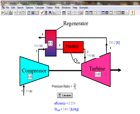 | Figure 1. Regenerative Gas Turbine (RGT) Modeling and Integration using EES |
3. Absorption Chiller
An absorption chiller is a closed loop cycle that uses waste heat to provide cooling or refrigeration. Absorption chillers use has been limited by their relatively poor efficiency at delivering cooling compared to vapor compressions cycles. For comparison, an absorption chiller typically has a coefficient of performance (COP) between 0.4 and 1.5, based on heat input.However, absorption chillers continue to be viable in some applications because they are able to utilize low temperature (<200°C) heat to provide cooling. In this sense, a COP for an absorption chiller cannot be compared to the COP of other cooling cycles because the input energy for an absorption chiller can be essentially free, for example when it is waste heat, as it would otherwise have been unused in most processes. Thus, in processes where low temperature waste heat is available and cooling is desired, it often makes sense to implement an absorption chiller to increase the overall energy efficiency of the process absorption chillers use a refrigerant-absorbent pair as a working fluid. The two most common combinations of working fluids used are ammonia/water and water/Lithium Bromide[6, 7].
4. Modeling of Ammonia/Water Absorption Cycle
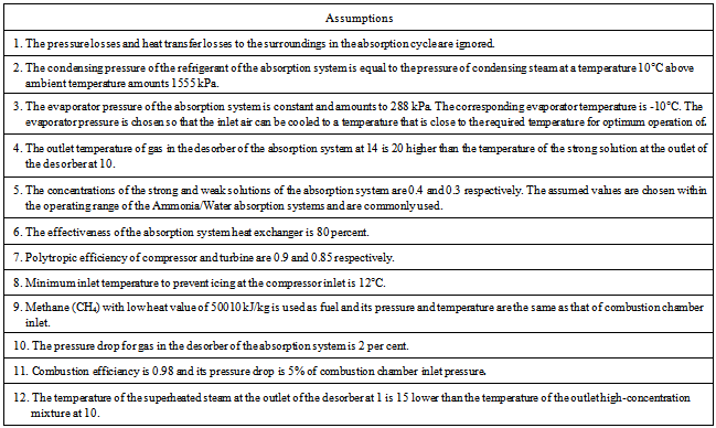
A single-effect ammonia (NH3)-water absorption cycle shown in Figure 3 is developed in this study and coupled with the gas turbine to cool the ail inlet to the compressor of gas turbine. The state points and assumptions of the cycle operation are summarized in Table 2.Table 2. State points and assumptions
 |
| |
|
5. Thermodynamic Analysis
A. desorberApplying the energy equation for the desorber of the absorption system yields: | (1) |
Where h14 is the enthalpy of gas exiting the desorber  are respectively the mass flow rates of gas entering the desorber, the weak solution exiting the desorber, the refrigerant exiting the desorber and the strong solution entering the desorber h9 ,h10 , h1:and are the corresponding enthalpies[8,9,10].Applying the mass balance equation yields:
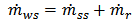 | (2) |
Using the concentration–mass flow rate relation gives: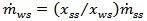 | (3) |
Where xss and xws are the concentrations of the strong and weak solutions respectively. Both concentrations are known and equal to 0.4 and 0.3. The high pressure of the cycle, Phigh, is equal to the condenser pressure, and the low pressure of the cycle, Plow, is equal to the evaporator pressure. The temperature of the outlet high-concentration mixture, T10 can be determined as a function of its concentration and pressure using a program called Engineering Equation Solver (EES) as follows: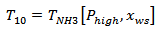 | (4) |
The corresponding enthalpy of the high concentration mixture, h10 can be determined as a function of its concentration and temperature using EES so that. 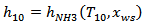 | (5) |
An equation can be written for the temperature of gas at the desorber outlet in relation to the temperature of the high concentration mixture at point 10 of the cycle (Figure 2). | Figure 2. Schematic diagram of the recuperated cycle with absorption inlet cooling |
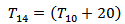 | (6) |
The gas pressure at the outlet of the desorber can be determined using assumption. The enthalpy of the outlet gas can be determined as a function of its pressure and temperature using EES as: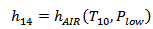 | (7) |
An equation can be written for the temperature of the outlet steam in relation to the outlet high-concentration mixture at point 10 using the following assumption: | (8) |
The enthalpy of the outlet steam can be determined as a function of its pressure and temperature using EES as: | (9) |
B. Heat exchangerThe heat exchanger (HE2) effectiveness is defined as: | (10) |
Where T11 and T8 are the temperatures of the outlet weak solution and inlet strong solution respectively. The temperatures T8 can be determined as a function of pressure and concentration using EES as: | (11) |
Applying the energy balance equation yields: | (12) |
Where h11 and h8 are the enthalpies of the outlet strong solution and inlet weak solution respectively. The enthalpies h11 and h8 can be determined as a function of the temperatures and concentrations of the solutions using EES as: | (13) |
 | (14) |
Equations (1 to 14) are solved simultaneously for the unknowns h1, h11 , h8 , h10 , h9, h14 ,  T1 , T11 , T8, T10 and T14 using EES. The results were presented in Figures 3 to 6 shown below.
6. Results and Discussion
From the previous analysis of the designed absorption cooling cycle. The outside air is cooled before entering the compressor and as a result the performance of the power plant will be better. The analysis were carried out for various exhaust gas turbine temperatures (153-200)°C and the cooling capacity has been getting cooler air up to 7°C for (Tamb=35°C ) The results of this study are shown in Figure 3 and 4 below.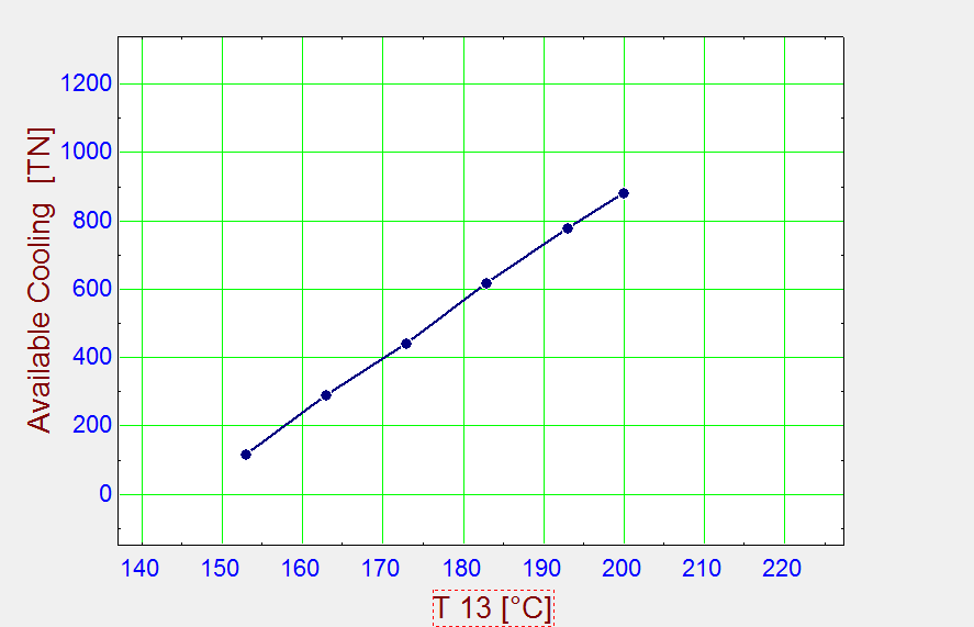 | Figure 3. cooling capacities of chiller designs at various exhaust temperatures (T13) |
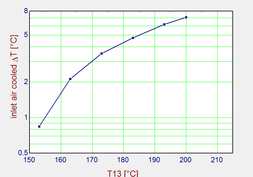 | Figure 4. Inlet air cooled °C at various exhaust temperatures (T13) |
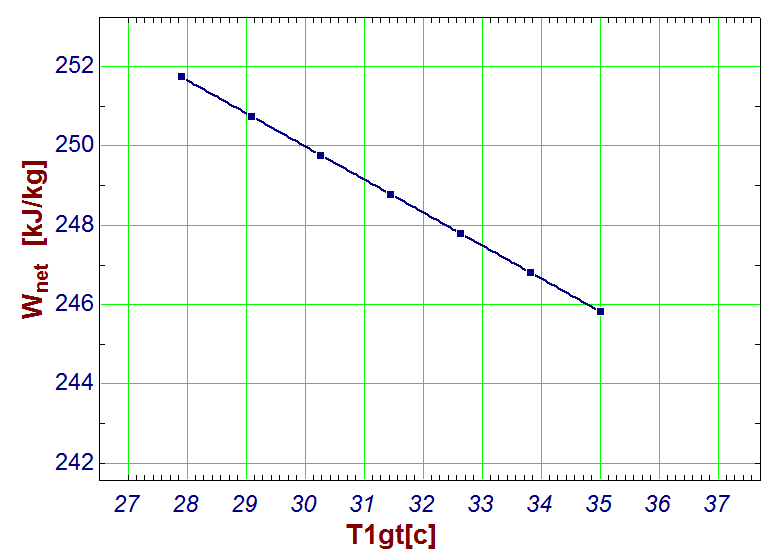 | Figure 5. Inlet cooling improves the work net of the gas turbine cycle |
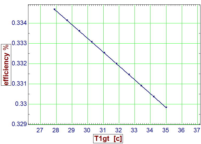 | Figure 6. inlet cooling improves the work net of the gas turbine cycle |
The inlet air cooling improves both the efficiency and the work net of the gas turbine cycle as shown in the Figures (5) and (6) below. As a result of decreasing inlet air temperature, the work net of the power plant improved by 5.9 percent and the efficiency of the power plant improved by about 0.49 percent.
7. Conclusions
The exhaust gases of gas turbine power plant carry a significant amount of thermal energy that is usually expelled to the atmosphere; this causes reduction in net work and efficiency of gas turbine. On the other hand, the generated power and efficiency of gas turbine plants depend largely on the temperature of the inlet air, So that they both increase as the inlet air temperature decreases. The mentioned two problems can be solved by installing an absorption refrigeration cycle (ARC) at gas turbine inlet, working with thermal energy of exhaust gases. In this research, effect of inlet air cooling on gas turbine performance is studied. The work shows that:• The compressor air inlet temperature decreases as exhaust temperatures (T13) increase. As a result the net work of the gas turbine will increase.• Absorption cooling could improve efficiency by about 0.49 percent.• Absorption cooling could improve the work net cycle by about 5.9 percent.
Nomenclature
ARC: Absorption Refrigeration Cycle.COP: Coefficient of Performance.e: heat exchanger effectivenessEES: Engineering Equation Solver.h: enthalpy (kJ/kg).: mass flow rate (kg/s).P: pressure.RGT: Regenerative Gas Turbine.T: temperature (oC).x: concentration (mass fraction).
Subscripts
amb : ambient.g : generator (desorber).NH3 : ammonia.r : refrigerant.ss : strong solution.ws : weak solution.
References
| [1] | Farzaneh-Gord, M., Deymi-Dashtebayaz, M., “Effect of various inlet air cooling methods on gas turbine performance”, Energy, Volume 36, Issue 2 , pages 1196–1205, 2011. |
| [2] | John W. Sawyer, Gas Turbine Engineering Handbook Volume 1, third edition, Turbomachinery International Publications, 1985. |
| [3] | Cengel, Y.A., Boles, M.A., Thermodynamic an Engineering Approach, 7th edition, McGraw-Hill Book Co., 2011. |
| [4] | Shepherd, D. G., Introduction to the Gas Turbine, D. Van Nostrand Co., NY, 1949. |
| [5] | Ravi Kumar N., Dr. Rama Krishna K., Dr. Sita Rama Raju A.V., “Improved GasTurbine Efficiency Using Spray Coolers and Through Alternative Regenerator Configuration”, 18th National and 7th ISHMT-ASME, 4- 6 January 2006. |
| [6] | Velasco Gomez E., Rey Martinez F.J., Varela Diez F., Molina Leyva M.J., Herrero Martin R., “Description and Experimental Results of a Semi-ndirect Ceramic Evaporative Cooler”, International Journal of refrigeration, Volume 28, Issue 5, August 2005, Pages 654-662. |
| [7] | Alhazmy M.M., Najjar Y.S.H., “Augmentation of Gas Turbine Performance Using Air Coolers”, Applied Thermal Engineering, Volume 24, Issues 2–3, Pages 415–429, 2004. |
| [8] | Lieb EH, Yngvason J., “A fresh look at entropy and the second law of thermodynamics”, Physics Today, Volume 53, Issue 4, 32-39, 2000. |
| [9] | Kakaras, E., Doukelis, A., Karellas, S., “Compressor Intake-Air Cooling in Gas Turbine Plants”, Energy, Volume 29, Issues 12–15, Pages 2347–2358, October–December 2004. |
| [10] | Thamir K. Ibrahim, M. M. Rahman, Ahmed N. Abdalla, “Improvement of gas turbine performance based on inlet air cooling systems: A technical review”, International Journal of Physical Sciences Vol. 6(4), pp. 620-627, 18 February, 2011 |
 Abstract
 Reference
 Full-Text PDF
 Full-text HTML