-
Paper Information
- Previous Paper
- Paper Submission
-
Journal Information
- About This Journal
- Editorial Board
- Current Issue
- Archive
- Author Guidelines
- Contact Us
International Journal of Energy Engineering
p-ISSN: 2163-1891 e-ISSN: 2163-1905
2013; 3(5): 242-255
doi:10.5923/j.ijee.20130305.03
High Velocity Impact Response Evaluation of a Glass Fibre Reinforced Polymer (GFRP) Composite - Amour Body
 Abstract
 Reference
 Full-Text PDF
 Full-text HTML
Onyechi Pius C.1, Edelugo Sylvester O.2, Ihueze Chukwutoo C.1, Obuka Nnaemeka S. P.3, Chukwumuanya Okechukwu E.1
1Department of Industrial and Production Engineering, Nnamdi Azikiwe University, Awka, Nigeria
2Department of Mechanical Engineering, University of Nigeria, Nsukka, Nigeria
3Department Mechanical and Production Engineering, Enugu State University of Science and Technology, Enugu, Nigeria
Correspondence to: Obuka Nnaemeka S. P., Department Mechanical and Production Engineering, Enugu State University of Science and Technology, Enugu, Nigeria.
| Email: |  |
Copyright © 2012 Scientific & Academic Publishing. All Rights Reserved.
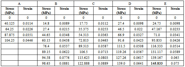
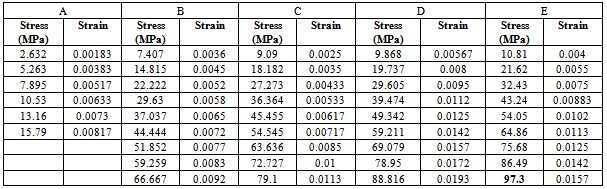
Impact on composites is a very complex phenomenon and function of many parameters influencing its analysis. This research developed an armour protecting body of Glass Fibre Reinforced Polyester (GFRP) composite laminates of varying thicknesses of 8mm, 12mm, 16mm, 20mm, 24mm, and 28mm. the impact response of these composites was investigated. The impact resistance and subsequent load-bearing capacity of the composites depend on many factors such as; fibre and matrix properties, fibre-matrix lay-up, number of layers or ply, thickness and impact velocity. These GFRP composites were targeted with a high velocity of 355m/s, using two types of life bullets (Ogival and Conical nosed). The developed composite armour proved considerable strength of 145.83MPa before ballistic deformation and 97.3MPa after ballistic deformation. Ballistic impact tests show that 5Samples out of the 6 Samples produced were able to withstand the impact velocity of the bullets, with Sample E showing a complete absorption of the bullet, while Sample F was perforated.
Keywords: GFRP Composite, Armour Body, Impact Velocity, Ogival Nosed, Conical Nosed, Ballistic Impact
Cite this paper: Onyechi Pius C., Edelugo Sylvester O., Ihueze Chukwutoo C., Obuka Nnaemeka S. P., Chukwumuanya Okechukwu E., High Velocity Impact Response Evaluation of a Glass Fibre Reinforced Polymer (GFRP) Composite - Amour Body, International Journal of Energy Engineering, Vol. 3 No. 5, 2013, pp. 242-255. doi: 10.5923/j.ijee.20130305.03.
Article Outline
1. Introduction
- Glass Fibre Reinforced Plastic (GFRP) automobile, ships, aeroplanes, and armoured vehicle bodies production offers Nigerians an appropriate technology. The problems of heavy initial capital investment on high-temperature furnaces and heavy press with complex dies without their maintenance technology are very significant. GFRP production is very cheap and do not require skilled manpower.However, a major concern about the use of the composite is their low resistance to out-of-plane localized impact loading. A number of works have been reported in the fields of impact phenomenon of fibre reinforced composites materials. Especially, the damage resistance and damage tolerance under impact loading are of the most importance of composite material characteristics because they are often susceptible to impact. Impact on composites is a very complex phenomenon and function of many parameters influencing its analysis. The advanced composites materials are being looked upon as the key materials for applications in armoured vehicle technology, automobile, ship, aerospace industries and ballistic protection. The design of composite armour is a very complex task as compared to conventional single-layer metallic armour, due to the exhibition of coupling among membrane, torsion and bending strains, weak transverse shear strength and discontinuity of the mechanical properties along the thickness of the composite laminates. This has drawn attention of several researchers to study the penetration phenomenon in composite amours.The impact resistance and subsequent load-bearing capacity of composite depend on many factors such as fibre and matrix properties, fibre-matrix lay-up, number of layers or ply, thickness, and impact velocity. Cantwell et al (1989) and Prewo (1980) stated that the impact, resulting in complete penetration of laminate due to the high velocity is called ballistic impact and is of major concern to the armour designers. Further, the damage caused to the armour under high velocity impact is quite significant and has major effects on the dynamic properties of the laminates.
2. Literature Review
2.1. Properties of Glass Reinforced Plastics
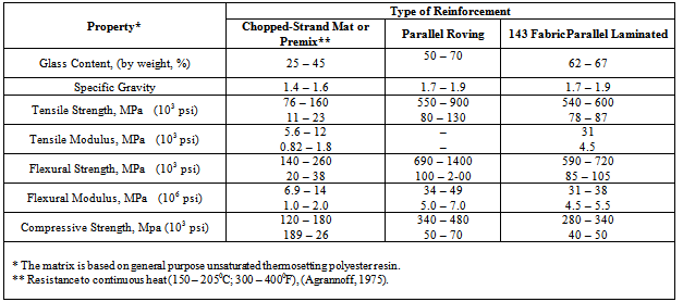
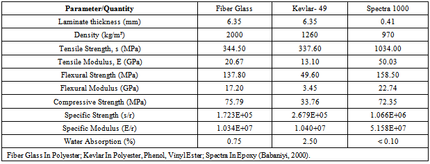
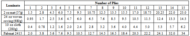
- The outstanding properties of composite materials led to products that are superior and competitive in the international markets. The glass-fibre reinforcement comes in a number of forms including roving, woven glass cloth and Glass mats[3]. Glass-fibre is the most common reinforcement used in polymeric composite formulation use in aerospace, aircraft, military and ballistic protection. Reinforcement plays a dominant role determining mechanical strength properties of composite. The primary reinforcement includes Glass-fibre or Fibre glass, Graphite and Aramid (Kevlar).The two main components of a GRP composite are the matrix and the reinforcing glass. The matrix is the continuous phase. In itself, the matrix does not provide strength, its role is essential, however, since it serves to bond the reinforcing glass-fibre together and to transfer the load to the reinforcing phase. The glass content of GRP composites effects strength properties and durability (the higher the glass-fibre content, the stronger the material). However, too high a glass content may result to insufficient impregnation, and therefore poorer bonding. The glass content of GRP reinforced with chopped strand mat generally varies between 25 to 35 ℅; for GRP reinforced with cloth, the glass content ranges from 50 to 63 ℅. Sheet material manufactured by hand lay-up process will have lower strength properties than those fabricated by a press-molding process.The range of mechanical and other physical properties is very wide, because of the great number of factors which define a GFRP composite. For example, the tensile strength at room temperature may vary from 69 MPa to 896 MPa or higher, wet strength retention from 50 to 95 % and specific gravity from 1.2 to 1.9. The range of some physical properties is given in Table 1. They are typical for GFRP sheet materials produced with normal care from general purpose polyester resin and reinforced with three types of glass-fibre reinforcement. More complete data on physical properties of GFRP composite can be found in reference [4],[5] and[6].The comparative average mechanical properties of high performance fibre laminates can be found in Table 2.Also, the thickness of the component laminate is the single most important factor to determine a moulding as it affects directly the quantity of re-enforcement and resin. Table 3 shows the number of plies of laminate in hand lay-up for a given average thickness of laminate.
|
|
|
2.2. Review of Related Works
- Since 1950, fibre-reinforced composites have been used in wide variety of industries. Industries as diverse as transportation, construction, marine, offshore oil, sporting goods have recognized those benefits and are extensively making use of these materials. Enetanya (1998) investigated the fibre- reinforced composite for the aircraft and automobile industries on a paper presented at a technical sessions of the Nigerian Society of Engineers. Edelugo (2000) worked on reinforcement combination for GRP in Auto-body works while[12] investigated the influence of the fibre reinforcement combination on the buckling failure of GFRP composites. Ballistic type of impact tests were studied by Europeans in an attempt to study speed effects of a projectile that would maximize the damage. The study of foreign objects became critical for speed and shape of indenters relationship. The first ballistic impact resistance test was conducted on the GRP in 1940. In their study it was found that the maximum de-lamination damaged area was a linear function of the force of impact whether the force was introduced by falling weight or static indentation tests. As impact testing of composite laminates becoming routine and matured, test methods and analyses have become well defined. In particular instrumented impact on non-catastrophic testing is being widely used where impact analyses have been broken down into dynamic response and quasi static response[13] and[14].The analysis of high velocity impact problems has been of interest for many years. Solution to these problems often require the inclusion of large strains and displacement, as well as the materials strength and compressibility effects, the analysis techniques are complicated and large computer codes are necessary to obtain these solutions. The earlier solutions of high velocity impact problems were often obtained with two-dimensional Lagrangian codes such as HEMP by Wilkin and TOODY II by[15]. Two-dimensional Eulerian codes such as HELP program by[16] were later applied to these problems. A three-dimensional version of HEMP has also been developed[17]. The finite-element method has recently been applied to two-dimensional impact problems involving severe distortion[18]. A comprehensive description of various finite-element methods is given in references works by[19] and[20]. The work presented herein is an extension of that presented in[18] with the technique being extended for axisymmetric, two-dimensional, triangular elements to three-dimensional tetrahedron elements,[21]. Various theories proposed for predicting the characteristics of penetration of composite laminates by different projectiles have been reviewed by[20], and[21]. The impact response and damage mechanism are very complex and depend on a number of parameters such as impact velocity, impact energy, impact angle. During high velocity impact by projectiles, the target response is controlled by the local behavior of the materials because of the relatively small impact mass and short contact duration. Therefore the available kinetic energy is usually dissipated over a small zone surrounding the contact area and the failure mode is dominated by perforation. High velocity projectiles owe their destructive penetrating ability to the kinetic energy they carry with them. Conversely, the efficacy of any material resisting such kinetic energy projectiles depends on its ability to absorb the kinetic energy. The energy absorption capacity in turn depends on target material properties. For a given set of properties of laminate targets, the absorption capability also depends on the anisotropic nature of the target material, the thickness of the target, the angle of attack and the type of projectile. Kumar and Bhart (1998) studied the effect of thickness of the laminates and the angle of attack on the energy absorption by the composite laminates and the area of damage caused by impact. Wen H.M et al (2001) and He et al. (2006) presented analytical equation for the prediction of the penetration and perforation of thick FRP laminates struck normally by missiles over a range of impact velocities.A variety of numerical techniques have been used to study and predict the behavior of composite laminates subjected to impact. Both solid mechanics and fracture mechanics have been used to analyze impact phenomena. In the fracture mechanics approach, change is assumed to occur around an initiated crack due to stress concentrations at the crack tip. Therefore, decision must be taken where crack initiation has occurred and model local crack growth phenomena. In solid mechanics approach, fracture and local phenomena are averaged to model global structural behaviours. Damage is predicted when values of the stress or strain field satisfy a failure criterion. A solid mechanics approach will be taken for this analysis to model global processes rather than treating local phenomena such as fibre/matrix interation and inter-lamina boundary effects. There are many examples in the literature of analytical treatment of impact on composite. To study the influence of various parameters affecting the penetration process in high velocity impact, the model should be able to describe the physical events, such as indentation, fibre breakage, de-lamination, bulging occurring during penetration.
3. Materials and Applicable Methods
3.1. Experimental Procedure
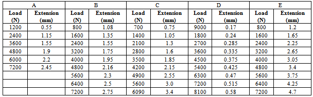
- The class of glass fibres used in this work is the matted woven roving E-glass procured from NYCIL Chemical Industries Nkpor, Idemili North L.G.A., Anambra State, Nigeria. E-glass class, which is a low alkali Borosilicate was initially, developed for electrical application, hence the designation E. The diameter of each E-glass fibre is about 0.01 mm with an average length of 50mm. It has a density of 2550kg/m3; Young’s Modulus of 72 GN/m3; and a strength of roughly 3.4 GN/m2. The Polyester Resin used for this work was also procured from NYCIL. It services as the polymer matrix (greatest in percentage of the reagents) for the sample preparation. The speed at which the resin sets can be controlled by the quantity of catalyst and accelerator used. Methyl Ethyl Ketone Peroxide (MEKP), served as catalyst to the reaction process. Cobalt II Ethyl Hexanoate acted as an accelerator for the release of the free of radical that enhances curing by the catalyst. Paraffin Wax was applied on the surface of mould to enhance the ease removal of the prepared sample from the mould untampered. This is also called a releasing agent. The hand lay-up method was used in formation of the composite materials. Here the polyester resin was applied on the mould evenly with the help of a hand brush to a thickness of about 1mm, then the woven roving fibres were lay-up in the mould and properly wetted out in a process known as fibre impregnation. More fibre plies were lay-up in the mould and compressed according to the required laminate thickness. For the thickness of 28 mm, 24 mm, 20 mm, 16 mm, 12mm and 8mm, the number of plies were 22, 18, 15, 12, 9, and 6 respectively. The fibre content by volume fraction varies from 0.48 to 0.50.
3.2. Formulations for Armour Applications (Ballistic)
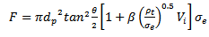
- It is assumed that the mean pressure (σ) applied normally to the surface of the projectile provided by a GFRP laminate material to resist penetration and perforation by the projectile can be decomposed into two parts, one part is resistive pressure (σs) due to the elastic-plastic deformations of the laminate material and the other is the dynamic resistive pressure (σd) arising from velocity effects. Thus;
 | (1) |
 and is taken to be
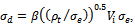 then equation (1) can be written as
 | (2) |
 and
and  are the density of the GFRP laminate and the initial impact velocity of the projectile respectively. The values of the term β were easily determined experimentally for simple geometries. For a unidirectional laminate β=1, while for a (0/90) cross-piled laminate with equal proportions of the fibre in the two direction β= 0.5. For a (±45, 90) composite with one quarter of the fibres in each direction β= 0.375. For a three dimensional random array β= 0.2[11]. Also, the values of the parameter β in the equations have been empirically determined and are taken to be equal to
  for conical-nosed and ogival - nosed projectiles respectively[25]. For fibre-reinforced plastic it has been observed in the static indentation tests[26] that the first term in equation (2) is related to the static strength of FRP laminates in compression in the two principal directions, through the thickness and in-plane. Abdulla and Cantwell (2006) used equation (2) to predict the ballistic limit of fibre-metal laminates. The same assumption (eqn. 2) was used by [28] in their study of the penetration of fibre-reinforced plastic.
3.2.1. Penetration of Semi-Infinite GFRP Laminates
- The types of projectiles (life bullets) that were used are the rigid projectile with ogival and conical nosed.
 | Figure 1. Projectile geometries (a) Ogival nose and (b) Conical nose |
|
3.2.2. Conical-Nosed Projectiles
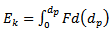
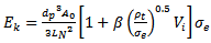
- For a rigid conical-nosed projectile, the motion and the final depth of penetration can be calculated if the resistive forces are known.(i) Case (i), dp ≤ LNThe resistive force of a conical-nosed projectile penetrating an FRP laminate target at normal incidence can be written as;
 | (3) |
 | (4) |
 | (5) |
 | (6) |
 | (7) |
 into equation (7) and rearranging gives that, [30].
 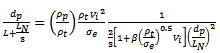 | (8) |
 Case (ii) dp > LNThe resistive force F can be written as;
 | (9) |
 | (10) |
 | (11) |
 into (11) and using
  gives the final depth of penetration as;
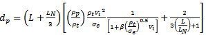 | (12) |
3.2.3. Ogival-Nosed Projectiles
- (i) Case (i) dp < LN[31]
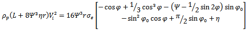 | (13) |
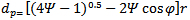 | (14) |
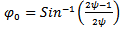 | (15) |
 | (16) |
 | (17) |
3.3. Ballistic Test
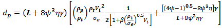
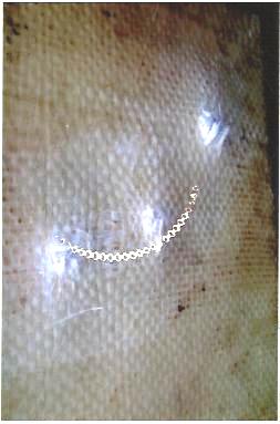
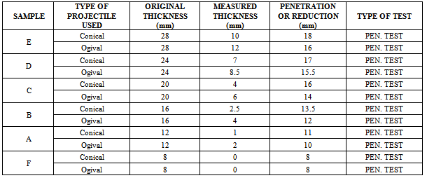
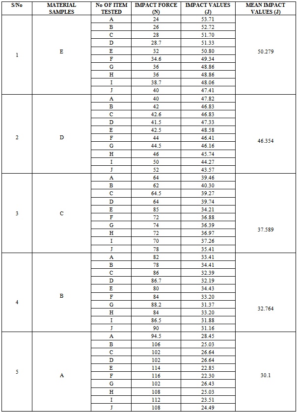
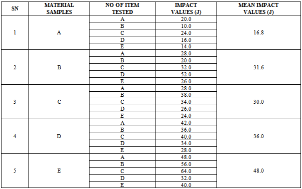
- The Ballistic or resistance to penetration tests were successfully done at the Nigerian Police Force (NPF) weapon divisional shooting ground at Uwani, Enugu, Nigeria. Six composite laminate armour sample plates of size 300mm by 400mm and thicknesses of 8mm, 12mm, 16mm, 20mm, 24mm and 28mm were targeted using two types of life bullets (Ogival and Conical nosed) of equal diameter and mass. The rifle used was the Beretta Cal 9 x 19 parabellum models 951 of muzzle velocity of 355m/s and the angle of attack was 00(normal). Figs. 2 to 7 show the ballistic impact, perforation and penetration on the six GFRP composite laminate samples.
 | Figure 2. Sample E, showing complete absorption of impact |
 | Figure 3. Sample D, showing minimal shattering by impact |
 | Figure 4. Sample C, showing some shattering and penetration, but no perforation |
 | Figure 5. Sample B, showing sign of penetration but no perforation |
 | Figure 6. Sample A, showing heavy shattering but no perforation |
 | Figure 7. Sample F, showing failure with complete perforation |
|
|
|
|
|
|
|
4. Experimental Results and Discussion
4.1 Impact (Ballistic) Test Results
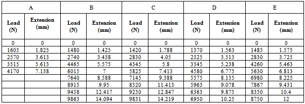
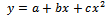
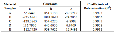
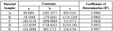
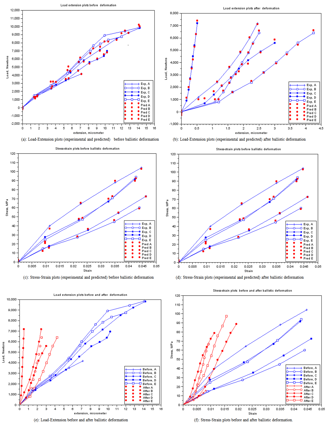 | Figure 8. Various responses of the GRP laminate samples before and after ballistic deformation |
 | (18) |
|
|
|
|
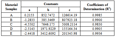
5. Conclusions
- This work shows that one of the governing factors in the damage resistance is the nose shape of the impacting projectile. Here the performance of the laminates could be properly tailored by controlling the strength parameters for the design against failure. It has also shown that great strides can be achieved in the production and testing (static and ballistic) of the armour protecting hand lay-up GFRP composite laminate plates. This work has also shown that; despite all odds, the hand lay-up composite armour developed, proved considerable strength of 145.83 MPa before ballistic deformation and 97.3 MPa after ballistic deformation. The ballistic limit or critical velocity can be successfully predicted for any thickness of the armour protecting body (GFRP laminate samples) produced. Finally, the data obtained from the experimental tests (tensile and impact) resulted to the plots of Fig. 8 which yielded the mathematical model of equation (18), the coefficients of this model were statistically analyzed and the resulting coefficients of determination are approximately unity an indication of good relationship (conformity) the between experimental and analytical results. Also, the result of Table 5 shows that Sample E actually gives the best impact absorption.