-
Paper Information
- Previous Paper
- Paper Submission
-
Journal Information
- About This Journal
- Editorial Board
- Current Issue
- Archive
- Author Guidelines
- Contact Us
International Journal of Energy Engineering
p-ISSN: 2163-1891 e-ISSN: 2163-1905
2013; 3(3): 200-207
doi:10.5923/j.ijee.20130303.11
Analysis of Three-Phase Self-Excited Induction Generator under Unbalanced Operations
 Abstract
 Reference
 Full-Text PDF
 Full-text HTML
Yatender Chaturvedi, Kanwarjit Singh Sandhu
Department of Electrical Engineering, National Institute of Technology, Kurukshetra, 136119, India
Correspondence to: Yatender Chaturvedi, Department of Electrical Engineering, National Institute of Technology, Kurukshetra, 136119, India.
| Email: |  |
Copyright © 2012 Scientific & Academic Publishing. All Rights Reserved.
Out ofgrid connected and self-excited modes of induction generators, later is used due to its ability for the conversion of wind energy into electrical energy over a wide range of operating speed. However the performance of such machines when subjected to single-phase load (domestic load) may deteriorate. Looking their importance, an attempt has been made to analyze the operation of self-excited induction generator(SEIG) under unbalanced conditions. In this paper, a new model based upon the load decoupling across the stator terminals & exact representation of negative sequence network has been proposed to predict the degree of unbalance, generated voltages and currents under unbalanced load and unbalanced excitation as well. Simulation results on three different machines have been used to frame the recommendations.
Keywords: Self-Excited Induction Generator (SEIG), Wind Energy, Unbalanced Operation, Renewable Energy, Degree Of Unbalance
Cite this paper: Yatender Chaturvedi, Kanwarjit Singh Sandhu, Analysis of Three-Phase Self-Excited Induction Generator under Unbalanced Operations, International Journal of Energy Engineering, Vol. 3 No. 3, 2013, pp. 200-207. doi: 10.5923/j.ijee.20130303.11.
Article Outline
1. Introduction
- At present most of the electrical power is being generated from the fossil fuels ( coil, oil, and natural gases), which have finite sources and may vanish in the future. Due to the rapid depletion of fossil fuels and the concept of environment protection, now a days more attention is being given towards the renewable energy resources like, wind, solar, hydro, biomass, geothermal etc. Out of these wind is a clean and abundant renewable resource which can produce electricity with virtually no pollutant gas emission. Induction generators are widely used for wind powered electricity generation in remote and windy locations because of their capability to operate with varying wind speeds. Furthermore, induction generators have some additional advantages such as low cost, reduced maintenance, rugged and simple construction, brushless rotor etc.To estimate and analyze the performance of self-excited induction generator under balanced operation, loop impedance and nodal admittance approach may be used[1-3]. These approaches employs the per-phase equivalent circuit representation of SEIG in order to obtain unknown values of per-unit frequency and magnetizing reactance.[3] explains the phenomenon of self-excitation in the induction machines which is essential for the operation of such machines in generating mode. A concept of capacitive requirements in induction generators is described in[4]. A new model which contains a power source on the rotor side was proposed in[5] which gives the basic concept of generator. The work proposed in[1-5] contributes the performance estimation of SEIG under three-phase balanced load and balanced excitation. However single-phase load (domestic load) may result in to an unbalanced operation of induction generators. So far the literature survey shows that a little attention has been given related to such analysis of SEIG. This leads to the focus of researchers towards the analysis of SEIG under unbalanced operations. Regarding to it[6] proposed the model based on “C-2C” combination for the excitation balancing in which the value of second capacitor is generally taken less than twice the value of first capacitor.[7] Proposed a reduced circuit for three-phase generator load system consisting of two impedances in series out of which one represents load impedance and another one represents the input impedance of SEIG. The study of SEIG under unbalanced operation was continued[8] by omitting magnetizing branch and simplifying the negative sequence network and by taking per unit generated frequency as per unit speed of machine. A two port model is proposed by[9] for the analysis of unbalanced operation of self-excited induction generator in which magnetizing reactance for both the sequence networks was taken same.[10] Proposed a mathematical model for various generator-load combinations for unbalanced operation of SEIG in which magnetizing reactance for both the sequence networks was taken same. A dynamic study of SEIG under balanced/unbalanced operations has been presented by[11]. One of the researchers[12] proposed a delta connected generator load model which includes the core losses and having same values of the magnetizing reactance for positive and negative sequence networks.[13] Presents the effects of various unbalancing in load & excitation on degree of unbalance where as various effects of degree of unbalance on performance of SEIG was given by[14]. In this paper a new model based upon the load decoupling across the stator terminals has been proposed for the analysis of SEIG under unbalanced operations using the symmetrical component approach. Magnetizing branch of negative sequence network which was generally opened by the research persons or taken same as that for positive sequence network has been included accordingly in the proposed model.
2. Modeling
- Figure1 represents the three phase self-excited induction generator feeding a three phase load. Figure 2 & Figure 3 shows the per-phase positive & negative sequence equivalent circuit representation under unbalanced operation of the machines.Application of KCL in Figure 1 at the nodes ‘a,b,c’ of delta connected load respectively, along with the symmetrical component approach yields,
 | (1) |
 | (2) |
 Further it can be shown that:
  | (3) |
 | (4a) |
 | (4b) |
 | (5a) |
 | (5b) |
 | (6) |
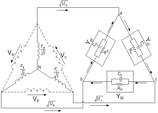 | Figure 1. Three-phase SEIG feeding three-phase load |
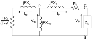 | Figure 2. Per-phase positive sequence equivalent circuit |
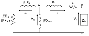 | Figure 3. Per-phase negative sequence equivalent circuit |
 | (7) |
 | (8) |
3. Computation of Generated Frequency and Magnetizing Reactance’s
- Application of Kirchhoff’s current law at nodes P & Q of the per-phase positive and negative sequence circuits of SEIG respectively and put their real and imaginary parts separately to zero gives:
 | (9a) |
 | (9b) |
 | (10a) |
 | (10b) |
4. Performance Equations
- Once the generated frequency and magnetizing reactance of positive & negative sequence networks is obtained, the air gap voltage Vgp for positive sequence network may be obtained from their magnetization curve of the respective machines as in Appendix-I. Now the steady state performance of the machines may be estimated using the following equations:
 | (11) |
 | (12) |
 | (13) |
 | (14) |
 | (15) |
 | (16) |
 | (17) |
 | (18) |
 | (19) |
 | (20) |
5. Results & Discussion
- Proposed modeling of SEIG as explained in the previous section is used here in order to estimate the steady state performance on the three test machines[Appendix1] under unbalanced operating conditions. Figure 4 to Figure 13 shows the simulation results on three machines with unbalanced load & excitation across the stator terminals.
5.1. Effects of Unbalanced Load
- Figure 4 to Figure 8 shows the simulation results for degree of unbalance, voltage & current when unbalanced is created by varying the load resistance of one phase i.e Ral only (Figure 1). Operating speed for all three machines are same and taken 1.028p.u. Large value of Ral indicates the open circuit and small value indicates the operation near to short circuit for the concerned phase. From Figure 4, it has been observed that any change of load resistance results in to an unbalance which can be defined in terms of degree of unbalance(as shown). However any change towards open circuit across phase ‘a’ results in to low degree of unbalance in contrast to change of resistance towards short circuit.Further as evident from Figure 5 to Figure 7, open circuit of phase ‘a’ may lead to over voltage across any phase of generator and such operations may be harmful for the insulation strength. Such problem does not arise in case of change of resistance towards short circuit. On the other end, change of resistance on any side may results in to excessive currents in any part of the machines. Therefore unbalance is to be permitted only up to the limit which does not results in to excessive currents (more than rated). Excessive currents will leads to an overheating of the machine & hence a complete damage. Observation of Figure 8 reveals that output power of all three machines remains almost same for certain degree of unbalance on both the sides (i.e towards open & short circuit). This limit for these machines in terms of Ral is from 1.7p.u to 1.0p.u i.e with a maximum degree of unbalance within 5% (Figure 4).
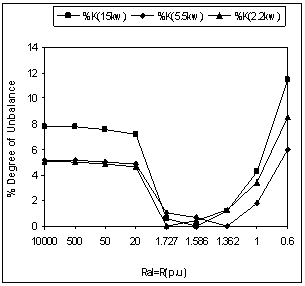 | Figure 4. Degree of unbalance with unbalanced load |
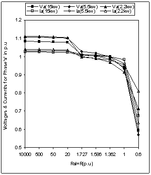 | Figure 5. Voltages & Currents for phase ‘a’ with unbalanced load |
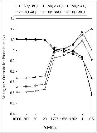 | Figure 6. Voltages & Currents for phase ‘b’ with unbalanced load |
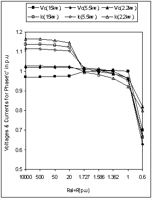 | Figure 7. Voltages & Currents for phase ‘c’ with unbalanced load |
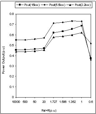 | Figure 8. Power output with unbalanced load |
5.2. Effects of Unbalanced Excitation
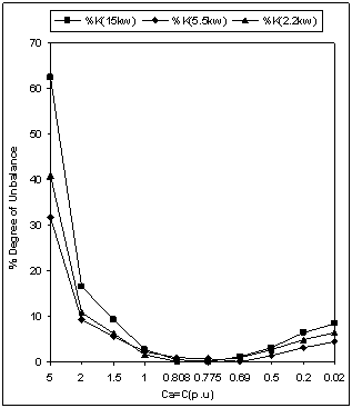
- Figure 9 to Figure 13 shows the simulation results for degree of unbalance, generated voltages & currents when unbalanced is created by changing the capacitance Ca (Figure 1). Larger value of Ca results in to a very small value of capacitive reactance (i.e towards short circuit operation) and smaller value of Ca results in to a large value of capacitive reactance (i.e towards open circuit operation).From Figure 9, it is found that any change in excitation capacitance of phase ‘a’, results in to a similar unbalance as in case of unbalanced loading (discussed in previous section). The only difference observed for all three machines are as:● Same change of excitation capacitance results in to more unbalance in contrast to change across load. This fact is true for change on any side(i.e towards open or short circuit operation).An observation from Figure10 to Figure 12 shows that the effects on generator voltages & currents due to changes in excitation capacitance are of same nature as observed for change in load resistance (previous section). The only difference observed for all the three machines are as:● Same change of excitation capacitance results in to excessive voltages & currents in contrast to load unbalance. Magnitude of over voltages & over currents comes out to be many times with excitation unbalance, which is highly undesirable operation.Analysis of Figure 13, may be useful to draw the limits for changes in excitation capacitance, which results in to a almost constant output, without exceeding the voltage and current limits.
 | Figure 9. Degree of unbalance with unbalanced excitation |
 | Figure10. Voltages & Currents for phase ‘a’ with unbalanced excitation |
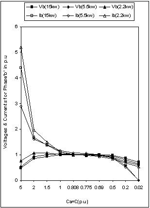 | Figure 11. Voltages & Currents for phase ‘b’ with unbalanced excitation |
 | Figure 12. Voltages & Currents for phase ‘c’ with unbalanced excitation |
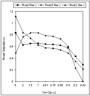 | Figure 13. Power output with unbalanced excitation |
6. Conclusions
- In this paper a new model has been proposed which is based upon the load decoupling across the stator terminals using the symmetrical component approach. Magnetizing reactance of negative sequence network generally omitted by the research persons or taken same valve as that for positive sequence network has been included accordingly in the proposed model. The proposed model when implemented to three different rating machines, is found to be useful to predict the effects of unbalancing due to the change of load as well as excitation capacitance. Simulated results as obtained may be used to define the limits of unbalancing without over voltages / over currents across any phase.
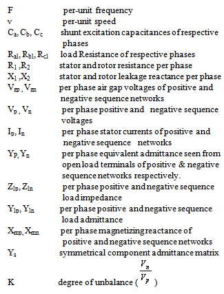
Nomenclature
Appendix-I
- Machine-1:3-phase, 15KW, 4-pole, 50 Hz, 415V, 30A, Delta connected squirrel cage induction machine with per-phase equivalent circuit parameters in per unit are as:
 The representation of magnetizing curve in per units is as :
  Machine-2:3-phase, 5.5KW, 4-pole, 50 Hz, 415V, 11A, Delta connected squirrel cage induction machine with per-phase equivalent circuit parameters in per unit are as:
 The representation of magnetizing curve in per units is as :
  Machine-3:3-phase, 2.2KW, 4-pole, 50Hz, 230V, 8.6A, Delta connected squirrel cage induction machine with per-phase equivalent circuit parameters in per unit are as:
 The piecewise representation of magnetizing curve in per units is as :
Appendix-II
 ,
,  ,
, 
 ,
,  ,
, 
 ,
,  ,
, 