Nemamcha Abdelmalek, Houabes Mourad
Department of Electrical Engineering, Badji Mokhtar University, Annaba, 23000, Algeria
Correspondence to: Nemamcha Abdelmalek, Department of Electrical Engineering, Badji Mokhtar University, Annaba, 23000, Algeria.
| Email: |  |
Copyright © 2012 Scientific & Academic Publishing. All Rights Reserved.
Abstract
the electromagnetic fields associated with inclined lightning channel are usually characterized by pronounced fine structure, this paper investigates and quantifies the effects of channel inclination on the return stroke electromagnetic field shapes in the close, medium and far lightning environnement. Using Antenna Theory (AT) model, which is extended to take into account the channel inclination, the electromagnetic fields expressions for vertical dipole are completed, and an inclined channel is properly modeled, vertical electric and azimuthal magnetic fields are computed. The field computations show that amplitudes and wave forms of the electromagnetic fields are affected more markedly by the channel inclination at close distances, and the induced voltage produced by inclined channel differs significantly from that associated with a straight channel.
Keywords:
Inclined Lighting Channel, Electromagnetic Field, Return Stroke, at Model, Induced Voltage
Cite this paper: Nemamcha Abdelmalek, Houabes Mourad, Electromagnetic Fields Produced by Inclined Return Stroke Channel, International Journal of Energy Engineering, Vol. 3 No. 3, 2013, pp. 176-182. doi: 10.5923/j.ijee.20130303.08.
1. Introduction
Electrical power system apparatus can be adversely affected by the cloud-to-ground (CG) lightning return stroke. The mis-operation failure of such apparatus may not only be due to a direct contact with the lightning discharge, but it indirect coupling with the lightning channel was possible, when the lightning return stroke produced near distribution networks[1]. As a result dangerously over voltage exceeds the system basic insulation level (BIL) specified in such a voltage level. In addition, electric equipments are at risk through electromagnetic field radiated.The issue of lightning returns stroke channel modeling has been often discussed and studied in literature[2, 3]. One of basic assumptions in most of models is that the channel is vertical, while the channel inclination effects have shown to be of great importance when calculating thelightning-induced effects on overhead lines. LeVine and Meneghini[4] investigated an arbitrary current filament located above a perfectly conducting ground plane driven by a traveling wave. In their theoretical analysis, they were able to develop exact and approximated solutions for the resulting fields. Their exact solution predicted both radiation and near fields regardless of the distance between the observation point and filament. Whereas, their approximated solution utilized far field approximation, and as a result, only yields electric field radiation constituents which occupy the Fraunhofer region of the filament. However, upon comparing the two solutions, they found the approximate solution failed the lower frequencies which are of particular importance in lightning studies. Lupo et al[5], in their study analysis, treated each tortuous path as a single line radiator with an arbitrary slope and height. They were able to develop closed-form solution for the electromagnetic fields by omitting any mathematical approximations. The channel inclination effect on lightning-induced voltages was first investigated by Sakakibara[6] who modified the Rusk’s model by adding appropriate additional terms in the field-to-transmission line coupling equations. He assumed that the charge density distribution along the leader channel is uniform and the current waveform is triangular. His method has been later extended to a channel with arbitrary configuration by Wu and Hsiao[7].In this paper, Antenna Theory model for the lightning return stroke channel is applied to investigate the effect of channel inclination. AT model characteristics for the vertical return stroke channel have already been presented[8]. The channel is represented as a lossy monopole antenna fed at its base. The return stroke current waveform predicted by the model exhibits dispersion and attenuation while travelling up along the channel, in accordance with available optical observations.In the first part of the paper, the theoretical basis of the Antenna Theory model for the lightning return stroke model is discussed, and then the expressions for electromagnetic field originated by a vertical dipole are extended to take into account an arbitrary dipole inclination. Finally the model is applied to investigate effect of channel inclination on electromagnetic fields at various distances, and the induced voltages on nearby overhead lines.
2. Theory and Adapted Model
Inclined return stroke channel, which is modeled by a straight and vertical monopole antenna above a perfectly conducting ground, is shown in figure 1. 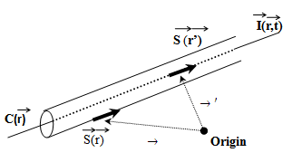 | Figure 1. Wire structure |
Lot of studies for determining the transient response of antennas and scatterers has grown steadily in recent years[9]. Transients may be dealt with both in time or frequency domain, a direct time-domain treatment of electromagnetic problems related to the lightning discharge is used. An integral equation developed for determining the time-dependent current distribution on wire structure excited an arbitrary time-varying electric field is reported in the literature, and will be briefly discussed. The electric field integral equation (EFIE) in time domain can be solved using the method of moments (MoM)[10].Computer code for time-domain solutions has been developed for thin wires in the free space by F. Barbosa and J. O. S. Paulino,[11]. Time dependent Maxwell’s equations provide starting point of our derivation. Desired integral equation derivation may proceed by Green’s vector identity, which leads to an integral equation relating J (surface current density) and E (electric field) on conductor’s surface under consideration. Assuming that surface consists in a small circular cross section in comparison with wavelength, current density surface integral can be replaced by a line integral along structure periphery (thin wire approximation). This approach leads to the same result as obtained by adopting assumption inherent in thin wire approximation at beginning. Latter approach is more direct it‘s employed here.
2.1. Problem Presentation
Consider a filamentary current I(r, t) flowing on path C(r), along which length variable is s (see Fig.2). Electric field it produces: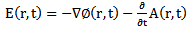 | (1) |
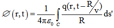 | (2) |
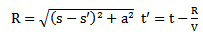
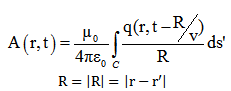 | (3) |
v: Velocity of propagation.r and t: Observation point location and time.r' and  : Denote source location and time respectively.
 : Unit tangent vectors to C(r) at
  and
and  respectively.Electric field integral representation due to filamentary current:
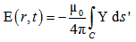 | (4) |
With: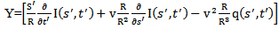 | (5) |
Assuming that I (s’, t’) and q (s’, t’) are confined to conductor axis (thin wire approximation), boundary condition on tangential electric field for a perfect conductor wire is: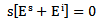 | (6) |
Ei: Applied field which induces the current I generating scattered field  By applying this boundary condition to tangential electric field at the conductor surface in Eq. (6), for this conducting wire in the following form:
 | (7) |
And: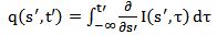 | (8) |
Since integration path in Eq. (7) is along C (R), while the wire radius displaces field evaluation path, R is always positive and therefore integral has no singularity, whose solution can be sought using moment method. Figure (4) shows that an incremental section of wire structure above a perfect ground, so image theory is used, in order to take into consideration ground effect. As a result: 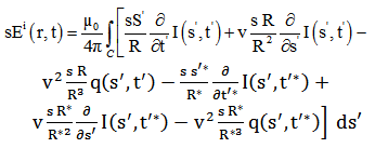 | (9) |
 And
And 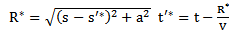
 : Image point of a source
  and
and  Corresponding unit vectors.
2.2. Numerical Approach
Integral equation given in Eq. (9) is solved by moment’s method; we first divide the thin wire into NS elementary segments of length  while time span is divided into Nt equal step of length
  . Then, a set of rectangular basis functions is defined for expressing known current in each segment, i.e.
2.3. Antenna Theory model
In AT model, return stroke channel (RSC) is considered as a lossy vertical antenna fed by a voltage source at its lower end, while for ‘engineering’ models, the input is a current waveform at base of channel. In order to compare ‘engineering’ models with AT model quantitatively, we need to use the same input current in all models. This means that voltage source for monopole antenna should produce the same current as channel-base current assumed in ‘engineering’ models.Voltage of source is given by following equation[12] 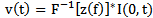 | (10) |
Where I (0, t): Current at the channel base, Z (f): Input impedance of the monopole antenna F-1 and *: Denote inverse Fourier transform and convolution integral operator, respectively. The input impedance of the monopole antenna, which is a function of length, radius and distributed resistance of channel, is calculated applying the MoM to EFIE. In transmitting mode of antenna, which is the case that has been studied here, applied field is zero everywhere except for segment at which the exciting voltage source is located.In AT model of return stroke, only two adjustable parameters are needed, the propagation speed and the resistance per unit length. The evolution of the current wave propagation along the channel is governed by antenna theory. To slow the propagating current at value consistent with observation, V< 3.108 m/s, we use ε > ε0,  in calculating the current variation and then use that current to calculate the field with ε=ε0.The arbitrary increasing of ε in determining channel current distribution serves to account for fact that channel charge is predominantly stored in radial corona sheath whose radius is much larger than that of channel core which carries longitudinal channel current, resulting in V< 3.108 m/s. This simulates an increase of shunt capacitance per unit antenna length due to corona. The use of (ε > ε0) additionally introduces effect of radiation into fictitious medium, but the resultant current distribution along channel is unlikely to differ significantly from case of no such effect. An alternative approach to modeling corona effect on propagation speed would be to introduce capacitive antenna loading.Ohmic losses in antenna further reduce v, but for selected value of resistance per unit length, this additional reduction in v is expected to be relatively small. Value of resistance per unit length is selected (by trial and error) to provide an agreement between model predicted and measured electric fields at close distances.Applying the MoM to Eq. (9) with AT model assumptions provides current distribution on RSC and on any nearby metallic structures[13]. As a result, is possible to directly include such structures in modeling stage of RSC, providing an effective means for study of lightning-related problems.
3. Electromagnetic Field Calculation
In case of monopole antenna model for lightning return stroke channel, there is a voltage source at base of channel. Applying Eq. (9) to waveform of this voltage source and solving proposed electric field integral equation by method of moments, current distribution is calculated.Electromagnetic field produced by a vertical infinitesimal dipole, located on and oriented along z axis has already been presented. Now, consider an infinitesimal dipole which is located at  with an arbitrary orientation defined by the following unit vector (see Fig. 2):
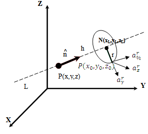 | Figure 2. An infinitesimal dipole with arbitrary orientation |
 | (11) |
Total electromagnetic Fields at point P caused by current which is flowing in a wire can be calculated by dividing wire into segments and adding the contribution of each segment.
4. Results and Discussion
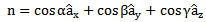
Described model in previous section have been employed to predict the effects of channel inclination on electromagnetic field distributions at different locations with respect to calculated channel at different distances.Return stroke electromagnetic fields were computed for a straight inclined channel located in YZ plane and make an angle of θ= 30° with the Z axis (Fig.3). 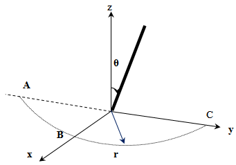 | Figure 3. Inclined Channel |
According antenna theory model, this channel is modelled as a monopole antenna which is feed at its base and radiates in free space. Once the current distribution along antenna is known using electric field integral equation, electromagnetic fields at any distance from channel can be computed. Fig. (4) Shows adopted channel-base current which corresponds to a typical subsequent stroke. 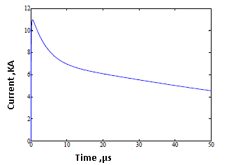 | Figure 4. Current in base of channel[14] |
The results for the electric fields and the magnetic flux densities are shown in figures 5, 6 and 7The observation points (A, B, and C), were assumed to be on ground and at different distances from the lightning striking point. While for the straight and vertical lightning channel the magnetic flux density in x-direction vanishes due to the radial symmetry, the inclined channel radiates small magnetic fields in x-direction, too. Due to the assumption of a perfectly conducting ground plane, the horizontal electric fields vanish for both channels.According to figures, the fields associated with the straight and the inclined channel mainly differ in the maximum amplitudes. In the following paragraphs these properties are discussed in more detail.Zhao and Zhang[15] presented a similar discussion of the electromagnetic fields radiated by tortuous return stroke channels. They investigated the azimuthal dependency of the remote fields (100m−100 km from the lightning striking point). Our work, concentrate on the radial dependency of the surrounding return stroke fields (350 m from the lightning striking point). Thus, it can be regarded as a supplement to the discussion of Zhao and Zhang.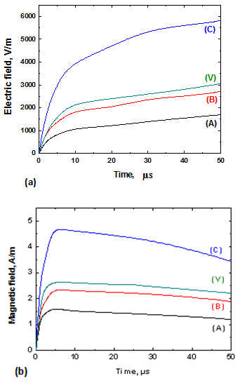 | Figure 5. Electric and magnetic field at 0, 35 km from the channel at different observation points, (V):vertical channel |
Radiated electromagnetic fields are plotted for different observation points (A, B, and C in Fig. 4) and distances from the channel (0.35, 4 and 50 km). At close distances (Fig. 5a and b) inclination effect is clearly observed. At t=50µs, Electric field value at point C is almost doubled with respect to the vertical channel. At this range, Magnetic field maximum value has markedly increased due to the channel inclination. At medium distance ranges (Fig. 6a and 6b), electric field shows the typical increasing ramp at all points. At point C, the steepness of this ramp is three times greater than that of vertical channel and magnetic field shows a hump which is more apparent at this point. At far distances (Fig. 7a and 7b); channel inclination effect on the electromagnetic fields appears to be less important.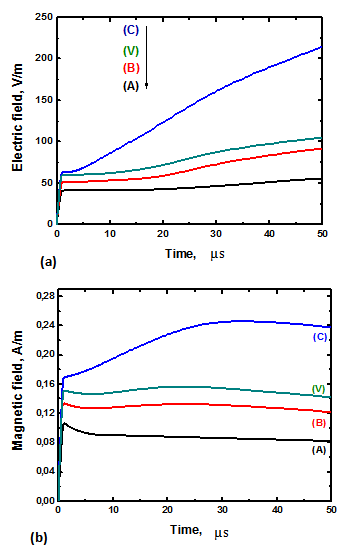 | Figure 6. Electric and magnetic field at 4 km from the channel at different observation points, (V): vertical channel |
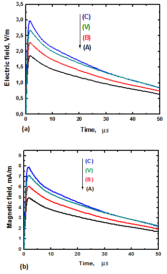 | Figure 7. Electric and magnetic field at 50 km from the channel at different observation points, (V): vertical channel |
4.1. Induced Voltages
Induced voltages have been evaluated for an overhead line composed of a single conductor, at height h=12 m above ground, parallel to the y-z plane, the length of the line is 1 km, at distances d of 100 m and 1500 m, we will consider 2 different geometries which are shown in Fig.8. Starting from the vertical channel (Fig.8.a) then a straight inclined channel will be considered with a channel inclination angle with respect vertical α=30°.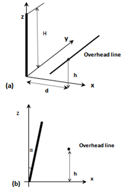 | Figure 8. (a) Straight channel, (b) Inclined channel |
It is clearly seen in Fig. 9, that for short and intermediate ranges, the effect of the inclination more important. Compared to the vertical channel, the amplitude of the induced voltage at a distance of 100 m is about 25% higher for points toward which the lowest segment is inclined. Similar behaviour is observed at 1500 m, although the induced voltage waveform exhibits a larger width. No overall tortuosity effect is noticed.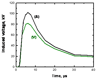 | Figure 9. (a). Induced voltage, at 100 m from the channel, (A): Inclined, (V): Vertical |
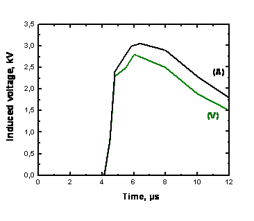 | Figure 9. (b) Induced voltage at 1500 m from the channel, (A): Inclined, (V): Vertical |
5. Conclusions
Antenna Theory model is applied to evaluate the electromagnetic field for an inclined return stroke channel. This method based essentially on solving the integral equation for electric field in time domain using method of moments.The electromagnetic fields expressions for vertical dipole are completed to take account the dipole inclination, This fields for an inclined lightning channel are computed using AT model at three different distances 0,350 (close), 4 (medium), and 50 km (far). The results prove that the vertical electric and azimuthal magnetic fields are clearly more affected at very close range by the lightning channel inclination than a vertical channel. Indeed, depending on the channel orientation and its relative position to the observation point or to the line, the channel inclination could result either in an increase or in a decrease of the electromagnetic field and induced voltage.Given the statistical nature of lightning channel and high variability of key parameters (such as return stroke current, return stroke speed, etc.), one can state that the assumption of a vertical channel represent a reasonable approximation in the calculation of lightning radiated fields.
References
| [1] | Rakov, V. A. and Uman, M. A.:’ Lightning: physics and effects’ (Cambridge University Press, 2003) |
| [2] | Rachidi, F. ‘Modeling Lightning Return Strokes to Tall Structures: A Review’, Journal of Lightning Research, January., 2007 vol. 1, pp. 16-31 |
| [3] | Mimouni, A., Rachidi, F.: ‘Electromagnetic environment in the immediate vicinity of a lightning return stroke’, Journal of lightning Research. 2006 |
| [4] | LeVine, D. M., and Meneghini, R.: ‘Simulation of radiation from lightning return strokes: the effects of tortuo-sity’, Radio Sci., 1978, 13, (5), pp. 801–809 |
| [5] | Lupò,G., Petrarca, C., Tucci, V., and Vitelli,M.:‘EM fields associated with lightning channels: on the effect of tortuosity and branching’, IEEE Trans. on EMC, vol., 2000, 42, no.4, Nov. pp. 394-404 |
| [6] | Sakakibara, A.:’ Calculation of induced voltages on overhead lines caused by inclined lightning studies’, IEEE Trans. Power Deliv., 1989, 4, (1), pp. 683–693 |
| [7] | Rusck, S.:’Induced lightning over-voltages on power transmission lines with special reference to over-voltage protection of low voltage network’. Thesis, Royal of Technology Stockholm Sweden Institute, 1957 |
| [8] | Wu, S. and Hsiao, W.:‘Characterization of induced voltages on overhead power lines caused by lightning strokes with arbitrary configurations,’ 1994 Int. Conf. on Systems, Man and Cybernetics, vol. 3, 1994, pp. 2706-2710 |
| [9] | Chowdhuri, P., and Anderson, J. G.:’Parameters of Lightning Strokes’, a Review IEEE Transaction on Power Delivrery, 2005, Vol. 20 |
| [10] | Delfino, F., and al.: ’Lightning return stroke current radiation in presence of a conducting ground: 1.Theory and numerical evaluation of the electromagnetic fields’, Journal of Geophysical Research., 2008, vol.113 |
| [11] | Barbosa, C. F., and Paulino, J. O. S.: ’An Approximate Time-Domain Formula for the Calculation of the Horizontal Electric Field from Lightning’, IEEE. Transactions on Electromagnetic Compatibility., 2007, 49, pp. 593 –601 |
| [12] | Kordi, B., et al.’Application of the antenna theory model to a tall tower struck by lightning’, Journal of Geophysical Research., 2003, vol. 108 |
| [13] | Shoory, A., et al., ‘On the Propagation of Current Pulses along Tall Structures Struck by Lightning’, in Asia-Pacific Symposium on Electromagnetic Compatibility, Beijing, China, 2010 |
| [14] | Pavanello, D., et al.:’Return Stroke Current Profiles and Electromagnetic Fields Associated with Lightning Strikes to Tall Towers: Comparison of Engineering Models,’ in International Conference on Lightning Protection, ICLP 2004, Avignon, France, 2004 |
| [15] | Zhao, Zk., and zhang.:’ Influence of channel tortuozity on the lighting return strocke electromagnetic field in the time domain’. atmos. Res., 91:404-409, 2009. |
 Abstract
 Reference
 Full-Text PDF
 Full-text HTML