Georg Kleiser, Valentin Rauth
Institute for Energy and Drive Technologies, Hochschule Ulm University of Applied Sciences, Ulm, 89075, Germany
Correspondence to: Georg Kleiser, Institute for Energy and Drive Technologies, Hochschule Ulm University of Applied Sciences, Ulm, 89075, Germany.
| Email: |  |
Copyright © 2012 Scientific & Academic Publishing. All Rights Reserved.
Abstract
Future energy systems will depend much more on renewable energy resources than the current ones. Renewable energy resources, in turn, fluctuate and are not permanently available to the same extent than fossil ones. In consequence, new approaches are required to balance electricity demand and production. One approach is to schedule the compressed-air production of industrial installations according to the current load and supply of the electric grid. To be able to do this, compressed-air has to be stored for peak load phases. Computer simulations are an efficient tool to judge the technical feasibility of such an approach and to compare it with other load management systems. This paper describes the thermodynamic fundamentals of compressed-air energy storage and their integration in a computer model. The obtained results from simulations were compared with results from measurements showing good consistency. Thus, the model was used to simulate different principles to store compressed-air. Systems with low pressure level and with high storage volume appear to be the most energy-efficient ones. In general the technology has the potential to be utilized in the electric load management. However, further simulations are required to determine the most economical solution.
Keywords:
Demand Side Management, Demand Response, Compressed-air, Energy Storage
Cite this paper: Georg Kleiser, Valentin Rauth, Dynamic Modelling of Compressed Air Energy Storage for Small-Scale Industry Applications, International Journal of Energy Engineering, Vol. 3 No. 3, 2013, pp. 127-137. doi: 10.5923/j.ijee.20130303.02.
1. Introduction
Under the pressure of rising energy prices, decreasing fossil energy resources and the problem of global warming, it is today one of the most important targets to increase the electricity production from renewables. Wind and sun power are expected to become the dominant energy resources in future energy systems. Energy from sun and wind is - in contrast to fossil energy resources - only temporarily available. A high availability of wind and sun power will affect an overproduction of electricity in future energy systems. Overproduction in this case means that more electric energy could be produced on basis of renewables compared to the amount, which is at the same time demanded by consumers. This, in turn, will impact the energy prices.In such times with an excess of renewables, electricity prices will decline to a minimum. Less availability of renewables, however, will push up the electricity prices. Electric power has to be utilized directly at the time of its production. Therefore, it is obligatory to find solutions to either store the electric energy or to reschedule activities requiring electric power.This is especially important for countries or regions, where the share of renewables in the electricity supply exceeds a level of 30%[1]. In Germany it is planned to cover more than 35% of the electricity supply by using renewable sources in 2020[2]. Means to improve the balance between energy supply and demand by adapting the consumer behaviour to the availability of energy are also known under the terms “demand side management” and “demand response”, respectively[3]. The term “demand side management” stands for an uncoordinated adaption of the electricity demand by the consumers as a reaction on price incentives. Demand response means a controlled activation or deactivation of energy consuming devices by a specialized corporation. Already in 2010 such systems were able to reduce the peak load in the USA by more than 50 GW[4].Any energy conversion process, which can be temporally shifted, is suitable to participate in a demand side management system. In particular, any system which provides a storable form of useful energy may be used for this purpose. Such systems are always able to supply useful energy on demand and without any loss of convenience from the storage. However, the situation on the electricity market will control in which time span the useful energy itself is actually produced. Typical examples for such energy conversion processes are the generation of cold, the air conditioning of buildings and the operation of heat pumps. In future more systems will be needed, which can be adapted to the supply – demand situation. In this respect, the production of compressed-air in industry has to be taken into account as well.Compressed-air production accounts for about 6% to 10% of the industrial electricity consumption in Europe[5]. So far, compressed-air is produced directly from electric power whenever it is needed. Industrial compressed-air networks are usually run with pressure levels in the range of 8 bars. In the past different studies were performed to examine the potential of compressed-air energy storage[6-8]. However, typically the focus of these studies has been the installation of large-scale power plants, which are able to re-generate electricity from the compressed-air in times of a lack of renewables. Only a few studies [9] focus on compressed-air storage in micro-scale units. To be able to judge the potential of demand side management with compressed-air and to optimize such systems, a survey was performed in following steps:1st step: Setting up a model based on the thermodynamic behaviour of each technical component which is required to build up the entire load management system.2nd step: Implementation of the model into a software code to be able to perform simulations3rd step: Validation of the model by simulating a test rig and comparing the results with real measurements obtained from the test rig.4th step: Running simulations of different technical approaches to store compressed-air and quantification of their economic benefitThe principle of demand side management is based on re-shaping the load profile of electricity consumers. The more the load is shifted from a high-price time span to a low-price time span, the better is the economic success of such a system.The electricity price and the electricity demand are extremely time-dependent values. In consequence, the simulation of such systems requires a model which is able to predict all interactions between these time-dependent values. A dynamic model is needed to prove the ability of different technical compressed-air storage systems to be used for demand side management purposes.Already in previous studies various compressed-air systems have been dynamically modelled. In [10] an industrial compressed-air network was modelled using Matlab Simulink. This study focuses on an evaluation of the control strategy of the compressor in respect of energy efficiency. However, the energy flows around the storage tank were not modelled in detail.In [11] the thermodynamic fundamentals of different kind of compressors are described and evaluated in respect of energy efficiency. In many other studies the large scale compressed-air energy storage is examined. In [12-13] the fundamentals of energy flows around a cavern as compressed-air storage system are described.The integration of large-scale compressed-air storage in regional or supraregional electric grids and the consequences in respect of grid stability and energy prices is the subject of further research work. Models to evaluate the electricity grid and prices are discussed in [6 – 8]. However, these surveys focus on dynamic modelling on the grid side without detailed analysis of the energy flows in the storage unit itself. It was the task of this survey to combine the different approaches used above – models for the dynamic simulation of large-scale compressed-air energy storage and their impact on electric grids on the one hand and models for industrial compressed-air networks on the other hand – to one single model describing the behaviour of compressed-air energy storage as part of a demand side management system at an industrial site.Due to this specific task the following assumptions have been made for the model and simulations:1st: The storage tank consists of a steel shell and is installed above ground-level like the current small ones used in industry. However, to achieve enough storage capacity either a higher pressure or volume must be applied.2nd: The time-spans, when compressed-air is stored in the tank, is controlled by the energy price. However, the influence of the demand side management system on the total load profile in the grid is supposed to be very small. In consequence, the small load increase due to the energy storage will not affect the energy price. Energy price profiles used in the simulation are calculated from price data from the stock market.3rd: The load profile of the compressed-air network is given from typical load profiles of companies working in two-shift or three-shift mode. The examined technical system must always provide the required amount of compressed-air. The model has to reproduce the physics of the compressed-air production and storage procedure. The fundamentals used for the models are explained in detail in section 2. The implementation of the model in a software code to run the simulation is shown in section 3. The model was validated by simulating a test rig and comparing the results with measurements. This is presented in section 4. Finally section 5 shows the main results of different simulation runs with possible storage systems. For these simulations the storage pressure and the tank volume have been varied.
2. Thermodynamic Fundamentals of Compressed-air Storage
With the model, the following sub-elements of compressed-air systems are intended to be simulated1. Compressor2. Storage tank3. Expander and throttle valve4. Compressed-air network
2.1. Compressor
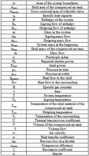
The compressor is supposed to work volumetrically. Consequently, the volume flow in the compressor will stay constant independent on other thermodynamic properties. The mass flow is determined from the volume flow considering the ideal gas law. Table 1. Nomenclature
 |
| |
|
The air passing through the compressor is supposed to perform a polytropic change of condition. In this case the temperature after the compressor Tout can be calculated from the ingoing temperature Tin and the pressure at inlet pin considering the pressure at the outlet pout and the polytropic index as indicated by equation 1 [10,11,14].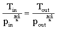 | (1) |
The ideal, required power Pideal to compress the air can be calculated from the mass flow through the compressor  , the specific gas constant R, the poytropic index and the difference between inlet temperature TStart and outlet temperature TEnd as indicated by equation 2.
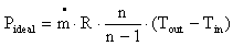 | (2) |
To calculate the required electric power to run the compressor further losses in the mechanical and electric parts of the compressor have to be taken into consideration. By introducing a factor for the compressor efficiency ηcomp the electric power Pel can be calculated from the ideal power Pideal according to equation 3. | (3) |
The mass flow through the compressor  is usually determined by a volume flow
  and by the inlet (or in most cases ambient) conditions. The mass flow can be calculated from the volume flow with the ideal gas low, where pin and Tin are pressure and temperature at the inlet, respectively, and R is the specific gas constant of air.
  | (4) |
Transient behavior of the compressor will be neglected in the model due to the fact that the thermodynamic changes of state in the compressor will perform much faster than those in the storage tank.
2.2. Storage Tank
The storage tank can be described by considering both, the mass and the energy balance around the air volume in the tank.The mass balance is determined by the fact, that a temporal change of the mass in the storage tank dm/dt is always a result of a mass flow into the tank  (increase of mass) or out of the tank
  (decrease of mass).
 | (5) |
An integration of the differential equation over the simulation time results in the current mass m at the time t. 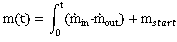 | (6) |
The integration constant mstart can be determined considering ideal gas behaviour and the conditions in the storage tank when starting the simulation (start pressure pstart, start temperature Tstart and the volume of the storage tank Vtank). 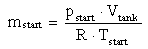 | (7) |
In analogy to the mass balance, the energy balance can be determined by equalising the change of the energy in the system with all energy flows across the system boundary.As mentioned earlier, the system boundary is set to the interface between the air in the tank and the shell. The area of the boundary is defined by the variable Atank. Figure 1 indicates schematically the energy flows across the system boundary of the storage tank.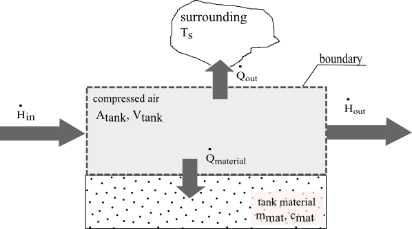 | Figure 1. Energy flows across the boundary of the storage tank |
The following energy flows have to be taken into consideration:Mass of compressed-air is able to flow either in or out of the tank carrying a certain amount of energy. This results in an ingoing flow of enthalpy  and an outgoing flow of energy
  , respectively. As compressed-air is considered to behave like an ideal gas the specific enthalpy depends only on temperature and does not depend on pressure. Thus, the ingoing flow of enthalpy
  is determined by the ingoing mass flow of compressed-air
  , its specific heat capacity and its temperature Tin.
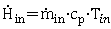 | (8) |
Note: The determination of the absolute enthalpy of the compressed-air to zero at zero temperature (0 K) is arbitrary. In the final energy balance only temperature differences appear. This will make this determination irrelevant for the final energy balance. The outgoing flow of enthalpy is determined accordingly. The temperature of the outflow is equal with the temperature in the tank T: 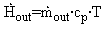 | (9) |
Apart from the energy transported by the flow of mass the heat flows across the boundary have to be considered as well. Heat can either flow into the shell of the tank or directly to the surrounding. The heat flow  to the surrounding is determined by the area of the boundary, the thermal transmission coefficient U and the difference between the temperature in the tank T and the temperature of the surrounding TS. In the model the surrounding is regarded to be of much bigger size than the storage tank. In consequence, the temperature of the surrounding will always stay constant.
 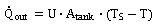 | (10) |
The heat flow to the material  is dependent on the heat transfer coefficient α (from the compressed-air to the material), the boundary area and the temperature difference between that of the shell material Tmat and that of the compressed-air inside the tank T.
 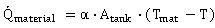 | (11) |
The heat conduction inside the shell is expected to be much faster compared to the heat transfer from the air to the shell. Any effects resulting from heat conduction inside the shell are neglected. Any heat flow into the shell however will affect a change of the temperature of the shell material Tmat. The temperature change of the shell material can be described by the following differential equation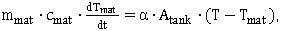 | (12) |
with mmat symbolizing the mass of the shell and cmat its specific heat capacity. The entire energy balance is shown in equation 13. The left side of the equation shows the change of the energy in the system by time, which can be a result of either a change of the system mass m or its specific enthalpy h. The right side of the equation summarizes all energy flows across the system boundary. In addition to the ones mentioned above, the system itself is also able to transfer power for a pressure change across the boundary, which is implemented in the differential equation by the term V dp/dt .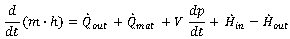 | (13) |
Equation 13 can be transferred to equation 14.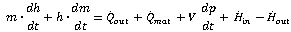 | (14) |
And considering equation 1 to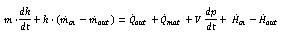 | (15) |
The specific enthalpy of the compressed-air is  | (16) |
and the change of the specific enthalpy in the tank by time is accordingly: | (17) |
Considering in addition equation 8 and equation 9 results in equation 18.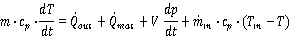 | (18) |
Equation 18 in combination with equations 12 enables a calculation of the temporal behaviour of any storage tank. This approach can be used not only for classical compressed-air storage tanks, but also for heat regeneration systems, which might be used to store the thermal energy in compressed-air systems. However, the above mentioned restrictions (e.g. equal temperature throughout the wall material) have to be respected.
2.3. Expander and Throttle Valve
If compressed-air is stored under higher pressure than the network pressure, a pressure reduction is required before feeding the compressed-air into the network. The pressure reduction can be either obtained by passing the air through a throttle valve or by running it through an expansion machine.The expansion machine is modelled in an identical manner than the compressor (see section 2.1). However, in case of expansion the pressure drop results in a decrease of temperature. The temperature decrease generates, according to equation 2, a negative work and power, respectively. This is, according to the thermodynamic sign convention, the indication, that the system is delivering power instead of consuming power.A throttle valve is modelled according to equation 19. The flow velocity through the valve w depends on the pressure difference Δp, the density of the air ρ and the resistance coefficient of the throttle ξ. The system is supposed to work significantly below sound velocity. Thus, the density will stay nearly constant. Calculation of the density is done according to the ideal gas law. | (19) |
The volume flow can be calculated from flow velocity considering the area of the throttle Athr. | (20) |
As the air is expected to react as ideal gas, the temperature of the air will not change when passing the throttle.
2.4. Compressed-air Network
The mode does not target to simulate the thermodynamic situation of the network in detail. The temporal behaviour of the compressed-air network itself is just implemented by using either a mathematical function or direct measurement results representing typical load profiles of production units.
3. Implementation in Matlab® Simulink®
Each component of the compressed-air system was modelled in Simulink® as a subsystem. This method allows an easy adaption of the model to new technical configurations. The required and the calculated variables of the important sub-models are shown in Fig. 2.Modelling of the compressor requires for each time step a value for the ingoing pressure p_in, the pressure at the outlet p_out, the volume flow (which is determined by the specification of the compressor), the temperature of the ingoing air and a signal to turn it on or off, which is submitted by a controller unit. The model supplies the current electric power, the temperature of the outgoing air and the mass flow out of the compressor. Other variables, which are not time-dependant, are adjusted inside the sub-model. In particular, the polytropic index and the efficiency of each compressor have to be specified there.A first comparison between simulations and measurements showed, that an implementation of a small storage volume as part of the compressor model provides a better correlation between model and real measurements. In consequence, the model of the compressor was extended to include a small storage volume. Therefore, a sub-model of the storage tank was added to that of the compressor to predict the changes of thermodynamic properties directly after the compression. Actually, such changes appear in the clearance volume of the pistons and in the ducts of the compressor. The volume, the area of the boundary and the wall mass have to be derived from the construction details of the compressor.An expansion machine (compressed-air motor) is model in complete analogy to the compressor (see section 2.4). The model for the storage tank requires the inflowing mass mass_in with its temperature Temp_in and the outflowing mass mass_out as input variable. In addition, pressure p_start and temperature Temp_start are required to calculate the initial mass in the tank. The temperature of the surrounding Temp_Sur is necessary for the calculation of the heat flow to the surrounding. The submodel evaluates with these data the pressure and the temperature in the tank and, in addition, the temperature of the shell Temp_wall.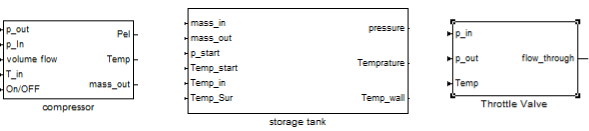 | Figure 2. Icons of the Simulink sub-models used for simulation |
The submodel of the throttle valves calculates the volume flow (flow_through) considering the pressure level before (p_in) and after (p_out) the valve. Additionally, the calculation of the density requires the temperature of the inflowing gas (Temp) as an input variable.
4. Model Validation
A Schneider UNM 410-10-50 W two cylinder trunk-piston compressor was used for model validation. The compressor is able to achieve pressure levels up to 10 bar gauge. It is compressing an intake volume flow of 410 l/min. The compressor is supplied with a storage tank of 50 l.The pressure was measured directly after the compressor and in the tank. In addition, temperature was measured directly after the compressor, in the tank and at the shell of the tank, respectively. All measurements are stored using a data logger (Hydra® from Fluke Corporation) and transferred to a personal computer for further evaluation.By measuring the temperature ratio while compressing against constant pressure the polytropic index can be determined from equation 1. The polytropic index of the compression in this compressor was found to be very close to 1.3, which corresponds quite well to values given in literature[10,11,14].Figure 3 and figure 4 show the measured and simulated results of a storage procedure. The compressor was run until a pressure of 7.2 bar was achieved in the storage tank. After that the compressor was switched off.The measured and simulated curves for the pressure in the storage tank are indicated by figure 3. The simulated pressure-time dependency matches exactly the measured one. In addition, the temperature levels measured after the compressor, in the tank and at the wall correlate quite well with the simulated ones (figure 4). However, the temperature-time-curves in figure 4 show that the real temperature in the storage tank reacts slightly time-delayed compared to the simulated one. The delayed reaction of the temperature during loading the tank might be explained by the volume of the piping, through which the air has to pass after the compressor. This in turn, however, can not explain the delayed reaction of the temperature in the cooling phase. After loading the storage tank, the mass in the tank stays constant. In consequence, only the heat transfers to the wall or to the surrounding can affect a change in temperature. If, however, the heat transfer coefficient used in the model was increased, the calculated maximum temperature in the tank would decrease. This, in turn, would be contradictory to the measurement results.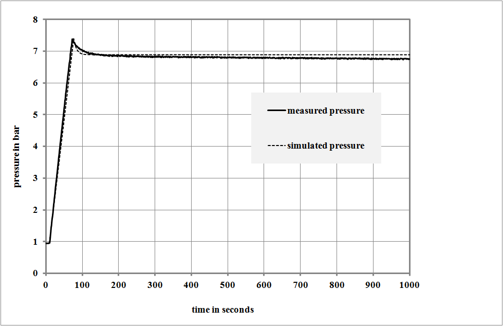 | Figure 3. Measured (solid line) and simulated (dashed line) pressure in the storage tank during compression |
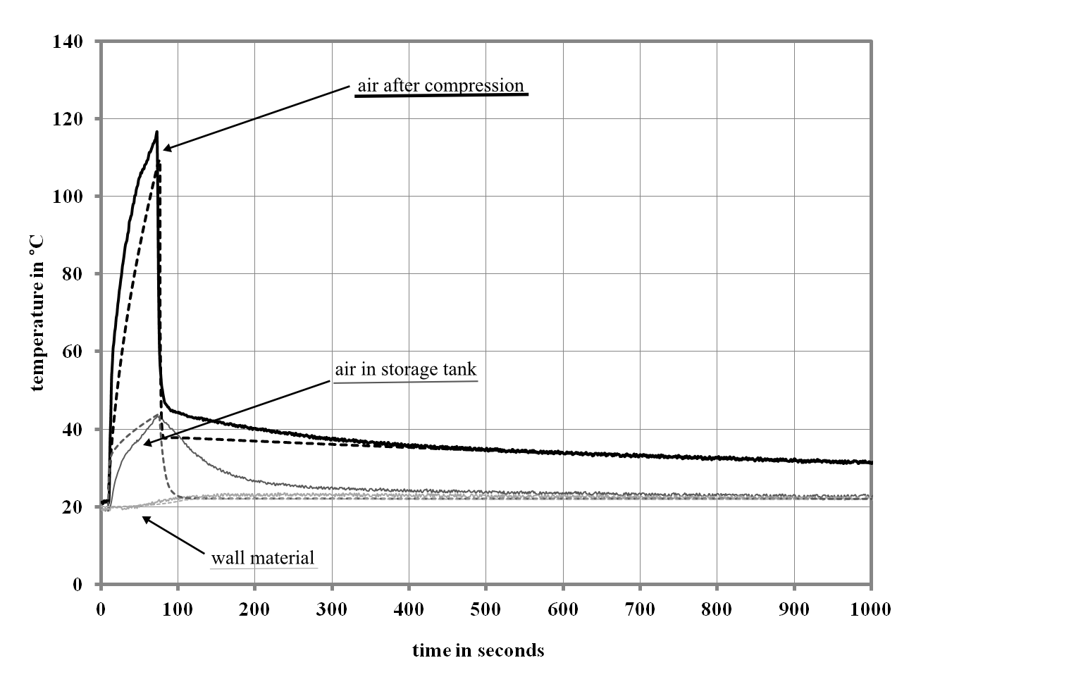 | Figure 4. Measured (solid line) and simulated (dashed line) temperature in the storage tank during and after compression |
One might consider the heat capacity of the temperature sensor itself as a further explanation for the effect discussed above. If the heat capacity was too high, it would also affect a delayed response of the measured temperature signal to the one expected in the gas phase. However, in view of the fact that the identical sensor, used at the exit of the compressor, is able to detect accurately much faster temperature changes, this hypothesis is disproved.Summarizing the results, the proposed model predicts accurately the time-dependant behaviour of pressure and temperature, respectively. The modelled reaction of the temperature in the tank shows solely a certain deviation to the measured results. This is most likely affected by a combination of the measurement set-up, especially the relatively small volumes compared to the surrounding, and the relatively low time-scales, which were used for model validation. In the simulation of bigger sized tanks and longer time spans this deviation is expected to be without importance.
5. Results
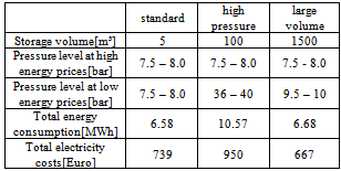
With the proposed model, different methods to store compressed-air in an industrial system were simulated. In a simple and easy approach compressed-air can be stored in a normal tank after compression either by increasing the volume of the storage tank or by increasing the pressure in the storage tank. The first approach requires space and is causing additional investment costs. The second approach requires additional energy, because the compressed-air has to be “over”-compressed up to a much higher pressure as that actually required in the network.To examine the differences between these approaches a typical scenario for the future energy market situation was created and simulated over a time period of 10 days. The assumed fluctuation of the electricity price and the air demand for a first test run is shown in fig 5. The electricity price fluctuation could reflect a typical winter situation in future energy market, where an excess of wind power in the night could result in a drop in prices. During day-time the higher load will increase the prices. The air demand was taken from a daily profile of a typical industrial site which is operating in three shift mode. In the simulation the pressure in the tank was controlled such, that in the event of a price reduction below 100 Euros per MWh the tank is load up to the maximum pressure. This pressure level is hold until the prices are again exceeding the 100 Euro level. In the following phase the air stored in the tank is used to supply the network with compressed-air.Table 1 is comparing three different scenarios. In the first column (standard) the energy consumption and electricity costs are calculated for a current standard design of a compressed-air system. The standard design consists of a small storage tank of 5 m³ and the pressure is controlled to stay always between 7.5 and 8.0 bar independently on the electricity price. In the configuration with high pressure in the tank, a tank volume of 100 m³ is used. This is 20 times the volume of the standard configuration. The tank is filled to a pressure level of 36 bar to 40 bar in time spans with low electricity prices. 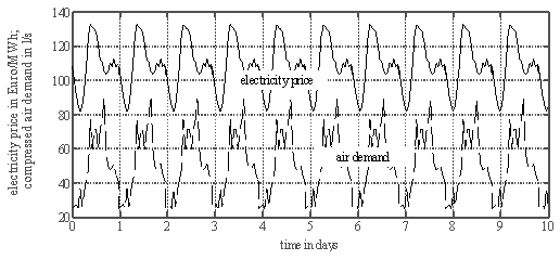 | Figure 5. Temporal profile of the electricity price and the air demand used in the simulation |
The alternative with large volume consists of a 1500 m³ tank. In this case the pressure is only increased by two bars compared to the standard configuration. In both alternatives the stored mass of air is nearly equal. In consequence, in both cases the storage tank can provide compressed-air over the same period of time without being re-filled. As table 2 indicates, the “high-pressure” alternative requires more energy than both versions with low pressure. Actually, in this case the air is compressed to much higher pressure level as really required in the network. Even though the electricity for this “over-“compression is taken from the grid in times with low electricity prices, the total electricity costs surpass those of the standard solution.Table 2. Comparison of compressed-air storage with a current standard configuration and with storage tanks working with high pressure and large storage volume, respectively: total energy consumption and electricity costs are calculated for 10 days of operation
 |
| |
|
In contrast, electricity costs can be reduced in case of the large volume version. This version requires only a small amount of additional energy for the compression. Due to the fact that this energy is used in a time span with significantly lower energy costs, the total electricity costs decrease.The pressure (dashed line) and the required electric power of the compressor (solid line) for the alternative with large volume are indicated by figure 6. The storage tank is, according to the supposed profile of the electricity price shown in figure 5, filled during the night hours. Air is taken from the storage tank from the early morning (first shift, 6:00) until middle of afternoon (15:30). Afterwards the pressure has decreased to the minimum level and the compressor has to be operated again.The time-dependency of pressure and electric power for “high pressure” alternative is shown in figure 7. Due to the lower storage capacity of this tank in case of an operation on low-pressure level, the compressor has to switch on and off more frequently in this phase compared to the version of figure 6. In both storage versions discussed so far the mass of air is sufficient to cover the air supply at noontime with especially high energy prices according to the proposed price profile. A reduction of the investment costs for such systems can be obtained by decreasing either the storage volume or the maximum pressure. However, this will decrease the time span, which can be covered without using the compressor. The result of such a simulation is shown in figure 8. In that case the storage volume was kept at 100 m³, however the maximum pressure was decreased to 10 bar. In that case, the content of the tank is already spent after approximately one hour of operation of the first shift. In times of the maximum energy prices (noontime) the compressor has to run again. The total electricity costs are in this example even slightly higher than in the standard configuration.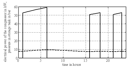 | Figure 6. Profile of electric power (solid line) and pressure (dashed line) throughout one day (starting at midnight 0:00) for compressed-air storage with a 1500 m³ storage tank and 10 bar maximum pressure |
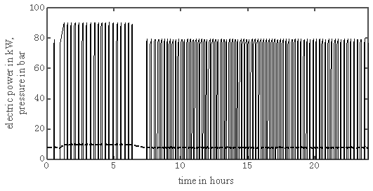
 | Figure 7. Profile of electric power (solid line) and pressure (dashed line) throughout one day (starting at midnight 0:00) for compressed-air storage with a 100 m³ storage tank and 40 bar maximum pressure |
 | Figure 8. Profile of electric power (solid line) and pressure (dashed line) throughout one day (starting at midnight 0:00) for compressed-air storage with a 100 m³ storage tank and 10 bar maximum pressure |
6. Conclusions
As shown in table 2, the compressed-air energy storage offers the possibility to participate in a demand side management system and to reduce energy costs. The first simulation runs have clearly shown that the utilization of low pressure levels in the storage tank is advantageous compared to high ones. This result stays in contrast to the recommended pressure level mentioned in literature for large-scale compressed-air storage units [6 – 8]. Those were usually run with pressure levels around 40 bar. This result, which might seem paradoxical at first sight, can be explained by the conditions chosen for the simulation. The prerequisite for designing the entire system was to provide enough compressed-air to bridge a certain time period without compressor. In this simulation a possible re-generation of electricity was not targeted.Under these circumstances the utilization of compressed-air stored at slightly higher pressure level than the one required from the network is preferable. Any compression to higher pressure levels requires additional energy, which will be finally lost. In principle, the air stored at higher pressure levels could be used to re-generate electricity, if it was run through an expansion machine before feeding it into the network. In that case the device will additionally produce electricity in time spans with high electricity prices. This, in turn, enables additional revenue from higher initial expenditure caused by the “over”-compression. This approach has to be evaluated in further studies.From the results obtained so far, a further important conclusion must be drawn. In case of using tanks with small storage capacities, it is extremely disadvantageous to initiate the loading and unloading of the tank by exceeding and underrunning, respectively, one simple price level. In that case prices slightly above the control level will demand the system to use the compressed-air from the tank. In consequence, in time spans with really high prices the tank content is already used and new compressed-air has to be produced with energy from the grid. This can be avoided by using more sophisticated control strategies with at least two different price levels causing the tank to be loaded and unloaded at real low-price and peak times, respectively. Currently the hourly difference in energy price at the exchange market throughout one day is still often quite small. Even though this might change in future, on the one hand it is required to keep down the investment cost of this technology in order to be competitive with other energy storage concepts. On the other hand, some additional technical features might improve the energy-efficiency of the entire system or might bring some additional benefit. In consequence, further studies are recommended. Especially the following concepts are promising:a. Installation of a separate tank with lower pressure and storage volume, which is only filled during extremely low-price phases and used during peak load time: This would enable the system to run better control strategies for the loading and unloading procedure. At the same time it would avoid an unnecessary “over”-compression of the air.b. Using an additional compressor/expander unit and an additional tank with a relatively high pressure level: If compressed-air was needed from the tank, the compressor would run in a reverse mode. In that case it is producing additional electricity during peak load time.c. The system might also be used to provide balancing energy (especially minute reserve). The balancing energy, clustered in combination with other users, can be offered at the energy stock market.d. The production and storage of compressed-air is furthermore connected with the generation of heat (during compression) and cold (during expansion): In this respect, such an installation could provide additional useful energy flows in peak load times.
ACKNOWLEDGEMENTS
The authors like to thank F. Ziegler, E. Bauer and L. Zylka for their support when performing the experimental work.
References
| [1] | J. Nitsch, Th. Pregger, T. Naegler, D. Heide, D. Luca de Tena, F. Trieb, Y. Scholz, K. Nienhaus, N. Gerhardt, M. Sterner, T. Trost, A. von Oehsen, R. Schwinn, C. Pape, H. Hahn, M. Wickert, B. Wenzel; Langfristszenarien und Strategien für den Ausbau der erneuerbaren Energien in Deutschland bei Berücksichtigung der Entwicklung in Europa und global“, Report, available online: www.dlr.de, Stuttgart, Germany 2012 |
| [2] | German Federal Ministry of Economics and Technology (BMWi): Energy concept for an environmentally sound, reliable and affordable energy supply, Berlin, Germany 2010 |
| [3] | Forschungsstelle für Energiewirtschaft e.V. (FfE): Demand Response in der Industrie: Status und Potenziale in Deutschland; online available: www.ffe.de; Germany 2010 |
| [4] | Federal Energy Regulatory Commission: 2010 Assessment of Demand Response and Advanced Metering, USA, 2011 |
| [5] | P. Radgen, “Bedeutung der Druckluftanwendung für Wettbewerbsfähigkeit, Energieverbrauch und CO2-Emissionen “ in: E. Ruppelt (Ed.); Drucklufthandbuch, Vulkan, Essen, Germany 2003 |
| [6] | S. Zunft, Ch. Jakiel, M. Koller, Ch. Bullough, “Adiabatic Compressed Air Energy Storage for the Grid Integration of Wind Power”, Sixth International Workshop on Large-Scale Integration of Wind Power and Transmission Networks for Offshore Windfarms, Delft, Netherlands, 2006 |
| [7] | Ch. Kruck, „Integration einer Stromerzeugung aus Windenergie und Speichersystemen unter besonderer Berücksichtigung von Druckluft-Speicherkraftwerken“, Dissertation, Universität Stuttgart, Germany 2008 |
| [8] | H. Lund, G. Salgi. “The role of compressed air energy storage (CAES) in future sustainable energy systems”, Energy Conversion and Management; Volume 50, 1172-1179, 2009 |
| [9] | Y.M Kim, D. Favrat, Energy and exergy analysis of a micro-compressed air energy storage and air cycle heating and cooling system, Energy, Vol. 35, 1, 213-220, 2010 |
| [10] | R. Maxwell, P. Rivera, Dynamic Simulation of Compressed Air Systems, 2003 ACEEE Summer Study on Energy Efficiency in Industry, Conference Proceedings 3, 147 – 156, 2003 |
| [11] | J.S. Chapell, A Transient Fluid and Thermodynamic Model of a Compressed Air System, Master Thesis, University of Alabama, USA 2011 |
| [12] | L. Nielsen, R. Leithner, Dynamic Simulation of an Innovative Compressed Air Energy Storage Plant - Detailed Modelling of the Storage Cavern, WSEAS Transactions on Power Systems, Vol. 4, 2009 |
| [13] | L. Nielsen, R. Leithner, Modelling and Dynamic Simulation of an Underground Cavern for Operation in an Innovative Compressed Air Energy Storage Plant, WSEAS 5th International Conference on Energy, Environment, Ecosystems, Development and Landscape Archchitecture, Proceedings, 285 – 293, 2009 |
| [14] | H. Dubbel, Handbook of Mechanical Engineering, Springer 1994 |
 Abstract
 Reference
 Full-Text PDF
 Full-text HTML