Masoud Asadi1, Ramin Haghighi Khoshkho2
1Department of Mechanical Engineering Azad Islamic UniversityScience and Research branch,Tehran, Iran
2Department of Mechanical Engineering & Energy engineeringPower and Water University of Technology,Tehran, Iran
Correspondence to: Masoud Asadi, Department of Mechanical Engineering Azad Islamic UniversityScience and Research branch,Tehran, Iran.
| Email: |  |
Copyright © 2012 Scientific & Academic Publishing. All Rights Reserved.
Abstract
This study explores the generation of entropy in a plate-fin heat exchanger with Louvered fins. The objectives are finding the number of total entropy generation units under a given heat duty and pressure drop constraints. To clarify method, a heat exchanger for cooling water is designed. The overall assessment of cooling system requires a trade-off between thermal performance and pressure drop. Entropy generation minimization (EGM) method is based on the theory that a thermodynamically optimized system is the least irreversible, or minimum entropy generation in the system. At air side, ten types of fins are employed. Eventually , based on the entropy generation and thermal performance a type of fin is selected for designing. To optimize the performance of selected heat exchanger, a equation for finding optimal mass flow rate is offered. Using this optimal mass flow rate, the entropy generation decreased up to 21% and also energy consumption about 5%.
Keywords:
Entropy Generation, Plate-Fin Heat Exchanger, Louvered Fin,
Cite this paper: Masoud Asadi, Ramin Haghighi Khoshkho, Entropy Generation in a Plate-Fin Compact Heat Exchanger with Louvered Fins, International Journal of Energy Engineering, Vol. 3 No. 2, 2013, pp. 110-118. doi: 10.5923/j.ijee.20130302.07.
1. Introduction
Compact heat exchangers are used in a variety of automotive, residential air-conditioning, oil industry and refrigeration. For air-side heat transfer augmentation , louvered fin are quite popular. Beauvais[1] was the first to conduct flow visualization experiments on the louvered fin array. He demonstrated that louvers, rather than acting as surface roughness that enhanced heat transfer performance, acted to realign the airflow in the direction parallel to themselves. Davenport[2]performed flow visualization experiments identical to those of Beauvais and further demonstrated two flow regimes , duct directed flow, and louver directed flow.Zhang et al. (1997) observed similar vortex shedding phenomena in a two-dimensionalcomputational study. Inline and offset parallel plate models were created with periodic boundary conditions to simulate an infinite array in all directions, thus ignoring entrance and exit effects. It was determined that the vortex shedding served to increase the overall heat transfer of thelouver. Unsteady solutions to the models showed that the vortices alternated shedding off the topand bottom of the plate and, correspondingly, had the effect of alternately increasing and decreasing the convective heat transfer along the plate surface. However, thetime-averaged result of the vortices resulted in a smooth, decreasing heat transfer curve from the leading edge to the trailing edge. This result disagrees with the DeJong et al. (1997) finding that showed a local heat transfer maximum at a location where the separated flow from the leading edge reattached to the plate at high Reynolds numbers. Both studies agreed, however, that the overall effect of vortex shedding was to increase the heat transfer in the array.Kurosaki et al. (1988) studied the effects that thermal wakes have on the heat transfer of downstream louvers in various arrangements of parallel plates. Using laser holographic interferometry to visualize isothermal contours of the wakes off the back of the plates, they were able to observe the manner in which the wakes from upstream plates progressed downstream and interacted with downstream louvers. Thermal wake visualization showed that increasing the Reynolds number caused the wake to narrow and maintain form further downstream, in agreement with the data of Springer and Thole (1998a) and the predictions of Zhang et al. (1997). Heat transfer measurements on downstream plates indicated that direct interactions with wakes had an adverse effect on the convective heat transfer of the plates. By shifting the louvers such that they avoided the wakes of upstream plates for as long as possible, the heat transfer of the downstream louvers was increased due to the relatively cooler fluid surrounding the louvers. Additionally, increasing the streamwise distance between aligned louvers was shown to have a minimal effect on the heat transfer of the downstream louver except at high Reynolds numbers. At high Reynolds numbers, the difference in thickness between the thermal boundary layer on the upstream and downstream louver became more significant, causing decreased heat transfer performance on the downstream louver as compared to the upstream louver.
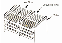 | Figure 1. Schematic of a typical louvered fin-and-tube heat exchanger |
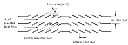 | Figure 2. Side view of a typical louvered fin geometry |
2.Thermal-hydraulic Design
In the thermal design of heat exchangers , two of the most important problems involve rating and sizing. Determination of heat transfer and pressure drop is referred to as rating problem. Determination of a physical size such as length, width, height, and surface area on each side is referred to as a sizing problem. When the heat transfer rate is not known or the outlet temperature are not known, tedious iterations with the LMTD method are required. In a attempt to eliminate the iterations, Kays and London in 1995 developed a new method called the method. Here, the heat capacity rate is defined as the product of mass flow rate and specific heat. The minimum capacity rate is the one that has a lesser capacity rate, and the maximum capacity rate is then the one that has a higher capacity rate. So, the heat transfer rate is, | (1) |
Here  and
and  are the heat exchanger efficiency, entering temperature difference and the minimum of heat capacity respectively.
 | (2) |
Where  is defined by:
 | (3) |
The other important parameter is NTU, Where it is considered as the number of transfer unit.  | (4) |
To calculate the outlet temperatures of both fluids, hot and cold, the equation of (5) and (6) can be considered.  | (5-a) |
 | (5-b) |
One of the key stage in designing a heat exchanger is accurate calculation of fluid properties. But before doing this, it is necessary to compute average temperature of each fluid. Here, according to shah research , if  the average temperatures would be
  | (6-a) |
 | (6-b) |
Heat transfer coefficient is,  | (7) |
 | (8) |
In this formula ,  and
and  are mass velocity and free flow cross sectional area respectively. Also, Colburn factor is,
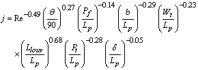 | (9) |
Where  is the louver pitch,
  the louver angle,
  the fin pitch,
  the tube pitch,
  the tube spacing,
  the tube outside width,
  the louver cut length, and
  the fin thickness.Furthermore , frictional pressure drop in both sides is given by:
 | (10) |
Here  and
and  are contraction and expansion coefficients.The noncircular diameter in the flow channels are approximated using the hydraulic diameter for the Reynolds number. The hydraulic diameter is defined as,
 Where
Where  is the wetted perimeter. The thermal design of a heat exchanger is aimed at calculating a surface area adequate to handle the thermal duty for the given specifications. Fluid friction effects in the heat exchanger are important because they determine the pressure drop of the fluids flowing in the system, and consequently the pumping power or fan work input necessary to maintain the flow.The number of passages
  on the hot side is defined as the air flow passages between flat tubes. The core width
  is expressed in terms of the number of passages
  as
as | (11) |
Where b is the tube spacing and  the tube height. Solving for the number of passages
  gives
gives | (12) |
The total number of fins is | (13) |
The total heat transfer area  is generally obtained from the sum of the primary area
  and the fin area
  . The primary area
  is calculated by subtracting the fin base areas from the tube outer surface areas, considering the circular front and end of the tubes.
 | (14) |
The total number of louvers in the core is obtained as | (15) |
So, the total fin area is the sum of the fin area and the louver edge area as | (16) |
Here  is the fin width. The total heat transfer area is,
 | (17) |
The minimum free-flow area  is expressed by:
 | (18) |
In coolant side, the total number of tubes is, | (19) |
Considering the circular shapes at both ends, the total heat transfer area  on the coolant side is obtained by,
 | (20) |
The free-flow area  on the coolant side is:
 | (21) |
3.Entropy Generation
In a large number of convective heat transfer situations the velocity and temperature fields are not known at each point in the medium. This is a case when the flow regime is turbulent or when the flow geometry is so complicated that an exact description of velocity and temperature is not available in analytical or numerical form.Consider the flow passage of arbitrary cross-section “A” and wetted perimeter “ P”. The bulk properties of the stream  are
are . In general, this heat transfer arrangement is characterized by a finite frictional pressure gradient
  and when heat is transferred to the stream at a rate
  , by a finite wall-bulk fluid temperature difference
  . Focusing on a slice of thickness dxas a system, the rate of entropy generation is given by the second law:
 | (22) |
In addition , for any pure substance we write the canonical relation as: | (23) |
This formula can be relate to average heat transfer and fluid friction information, which may be obtained experimentally or numerically for must duct geometries. The relationship between heat transfer rate  and wall-bulk fluid temperature difference is expressed in the form of Stanton number correlations:
 | (24) |
Here, note is that  is the average heat transfer coefficient. The fluid friction characteristics of a certain duct are reported usually in the form of friction factor correlations:
 | (25) |
In order to illustrate the dependence of  on Stanton number and friction factor information, we considering the case in which the heat transfer rate per unit length
  and the mass flow rate
  are specified. So,
 | (26) |
Under the present assumptions the duct configuration has two degrees of freedom. The wetted perimeter Pand the cross-sectional area Aor any other couple of independent parameters such as ( Re,D) or (G,D).Examining this Equation, it becomes evident that ah high Stanton number contributes to the reduction of heat transfer share of  , while a high friction factor has the effect of increasing the entropy generation rate due to viscous effects.In a round tube of diameter D, the rate of entropy generation per unit length is:
 | (27) |
Here, the Nusselt number is Nu=St.Re.Pr . If the pipe flow is turbulent and fully developed, the Nusselt number and friction factor are given by the well-known correlations(e.g., Bejan, 1995): | (28) |
 | (29) |
If  , in louver fins side the number of entropy generation is:
 | (30) |
Where  and
and  are respectively,
 | (31) |
 | (32) |
4. A case study
A coolant to air cross flow heat exchanger is design to cool the coolant( 50 percent ethylene glycol with water). Louvered fin geometry is employed on the air side. Both fins and tubes are made from aluminum alloy with  . The coolant flow in the flat tubes at
  and
and  , and shall leave at
  . Air enters at
  and
and . The inlet pressure of the air is at 100 Kpaabsolute and the inelt pressure of the coolant is at 200 Kpa absolute. The air pressure drop is required to be less than 500 Pa. The coolant pressure drop is recommended to be less than 7o Kpa.
Table 1. Fin geometries
 |
| |
|
5. Results and Discussions
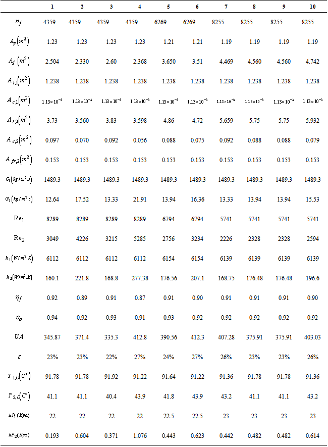
Table 2 denotes the fluid properties. At this stage ten heat exchangers with different Louvered fins are designed and compared for different terms. Table 3 gives this information.Table 2. Fluid properties
 |
| |
|
In tube side , with decreasing hydraulic diameter heat transfer and pressure drop characteristics will increase. However, the difference is not very considerable. For example, from 3/8-6.06fin with hydraulic diameter of 4.453 millimetre to 3/8-11.1fin with hydraulic diameter of 3.084 millimetre the increase in pressure drop is just1Kpa. For heat transfer coefficient and Reynolds number is the same. However, in Air side there is considerable difference between different type of fins. The important note is that Reynolds number, here, is a function of Louver gap and Louver spacing. | (33) |
Fins of 3/8(a)-6.06 and 1/2(a)-6.06have the biggest Louver gap, but between them the fin of 1/2(a)-6.06with 12.70 millimetre Louver spacing has the highest value of Reynolds number. Among cases of 1, 3,5,7, 8, 9 and 10 with the same Louver gap, the fin of 1/2-6.06has the highest Reynolds number. For the convective coefficient and mass velocity the trend is the same as Reynolds number.Table 3. Designing information
 |
| |
|
Table 4. Entropy generation
 |
| |
|
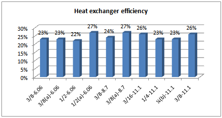 | Figure 3. Heat exchanger efficiency |
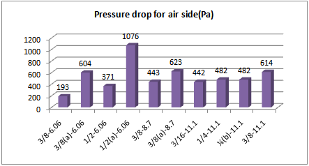 | Figure 4. Pressure drop for Air |
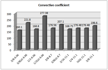 | Figure 5. Convective coefficient for Air |
Here, allowable pressure drop for Air side is 500 Pa , so the case of 7 is suitable, because it has the highest heat exchanger efficiency between all cases with allowable pressure drop. Table 4 gives entropy generation for Water and Air side. It is evident that entropy generation has a direct relation with heat exchanger efficiency , as in the case of 6 with the heat exchanger efficiency of 27% there are the largest value entropy generation in both sides. As previously mentioned , the selected fin for our designing is case of 7. However, here, the entropy generation is high and it is necessary decreasing it. To reach the optimal entropy generation in this case , we can change the mass flow rate. Equation of .(34) demonstrates the optimal mass flow rate based on entropy minimization. | (34) |
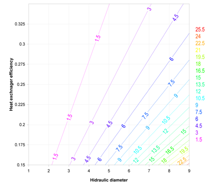
Figures of (6) and (7) show the function of optimal mass flow rate for Water and Air side respectively. As it is clear from these Figures the optimal mass flow rate will increase with growing hydraulic diameter dramatically. However, in tube side this increase is more. In tube side, some factors such as Louver angle, Louver spacing and Louver gap are also determinant. Using equation of (34) the optimal mass flow rate for Water and Air are 0.327 and 1.45 kg/s respectively. After doing mechanical and thermal designing process heat exchanger efficiency increased 5% and entropy generation decreased about 13.5% and 21 % for tube and fin side respectively.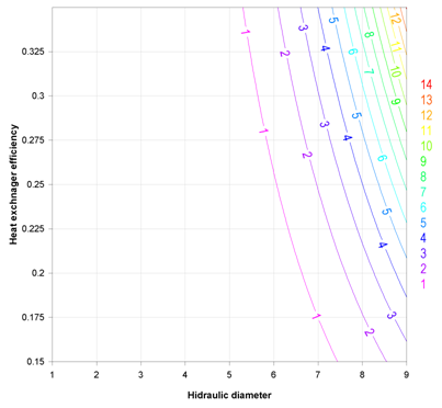 | Figure 6. Optimal mass flow rate for Water based on entropy minimization |
 | Figure 7. Optimal mass flow rate for Air based on entropy minimization |
References
| [1] | Beauvais, F.N. (1965), “An Aerodynamic Look at Automotive Radiators”, SAE Paper No.650470. |
| [2] | Davenport, C. J. (1983) “Correlation for Heat Transfer and Flow Friction Characteristics of Louvered Fin”, AIChESymp. Ser. 79, 19-27. |
| [3] | DeJong, N. C., and Jacobi, A.M. (1997) “An experimental Study of Flow and Heate Transfer in Parallel-Plate Arrays: Local, Row-by-row and Surface Averaged Behavior,”International Journal of Heat and Mass Transfer, Vol. 40, No. 6, pp 1365-1378. |
| [4] | Kurosaki, Y., Kashiwagi, T., Kobayashi, H., Uzuhashi, H., and Tang, S. (1988) “Experimental Study on Heat Transfer from Parallel Louvered Fins by Laser Holographic Interferometry,” Experimental Thermal and Fluid Science, Vol. 1 pp. 59-67. |
| [5] | Springer, M. E., and Thole, K. A. (1998b) “Experimental Design for Flowfield Studies of Louvered Fins,”Experimental Thermal and Fluid Science, Vol. 18, pp. 258-269. |
| [6] | Zhang, L. W., Balachandar, S., Tafti, D. K., Najjar, F. M. (1997) “Heat Transfer Enhancement mechanisms in Inline and Staggered Parallel-Plate in Heat Exchangers,” InternationalJournal of Heat and Mass Transfer, Vol. 40, No. 10, pp. 2307-2325. |


 and
and  are the heat exchanger efficiency, entering temperature difference and the minimum of heat capacity respectively.
 is defined by:


 the average temperatures would be


 and
and  are mass velocity and free flow cross sectional area respectively. Also, Colburn factor is,
 is the louver pitch,
  the louver angle,
  the fin pitch,
  the tube pitch,
  the tube spacing,
  the tube outside width,
  the louver cut length, and
  the fin thickness.Furthermore , frictional pressure drop in both sides is given by:
 and
and  are contraction and expansion coefficients.The noncircular diameter in the flow channels are approximated using the hydraulic diameter for the Reynolds number. The hydraulic diameter is defined as,
 Where
Where  is the wetted perimeter. The thermal design of a heat exchanger is aimed at calculating a surface area adequate to handle the thermal duty for the given specifications. Fluid friction effects in the heat exchanger are important because they determine the pressure drop of the fluids flowing in the system, and consequently the pumping power or fan work input necessary to maintain the flow.The number of passages
  on the hot side is defined as the air flow passages between flat tubes. The core width
  is expressed in terms of the number of passages
  as
as
 the tube height. Solving for the number of passages
  gives
gives

 is generally obtained from the sum of the primary area
  and the fin area
  . The primary area
  is calculated by subtracting the fin base areas from the tube outer surface areas, considering the circular front and end of the tubes.


 is the fin width. The total heat transfer area is,
 is expressed by:

 on the coolant side is obtained by,
 on the coolant side is:
 are
are . In general, this heat transfer arrangement is characterized by a finite frictional pressure gradient
  and when heat is transferred to the stream at a rate
  , by a finite wall-bulk fluid temperature difference
  . Focusing on a slice of thickness dxas a system, the rate of entropy generation is given by the second law:

 and wall-bulk fluid temperature difference is expressed in the form of Stanton number correlations:
 is the average heat transfer coefficient. The fluid friction characteristics of a certain duct are reported usually in the form of friction factor correlations:
 on Stanton number and friction factor information, we considering the case in which the heat transfer rate per unit length
  and the mass flow rate
  are specified. So,
 , while a high friction factor has the effect of increasing the entropy generation rate due to viscous effects.In a round tube of diameter D, the rate of entropy generation per unit length is:


 , in louver fins side the number of entropy generation is:
 and
and  are respectively,

 . The coolant flow in the flat tubes at
  and
and  , and shall leave at
  . Air enters at
  and
and . The inlet pressure of the air is at 100 Kpaabsolute and the inelt pressure of the coolant is at 200 Kpa absolute. The air pressure drop is required to be less than 500 Pa. The coolant pressure drop is recommended to be less than 7o Kpa.


 Abstract
 Reference
 Full-Text PDF
 Full-text HTML


