-
Paper Information
- Next Paper
- Previous Paper
- Paper Submission
-
Journal Information
- About This Journal
- Editorial Board
- Current Issue
- Archive
- Author Guidelines
- Contact Us
International Journal of Energy Engineering
p-ISSN: 2163-1891 e-ISSN: 2163-1905
2013; 3(2): 65-73
doi:10.5923/j.ijee.20130302.04
Optimum Induction Motor Speed Control Technique Using Particle Swarm Optimization
 Abstract
 Reference
 Full-Text PDF
 Full-text HTML
M. M. Eissa1, G. S. Virk2, A. M. AbdelGhany1, E. S. Ghith3
1Electrical Power and Machines Engineering at Helwan University, Egypt
2Electrical Power and Machines Engineering at South Westphalia University, Germany
3A master candidate in Systems Automation and Engineering Management; Master Degree Program Faculty of Engineering Helwan University, Egypt
Correspondence to: E. S. Ghith, A master candidate in Systems Automation and Engineering Management; Master Degree Program Faculty of Engineering Helwan University, Egypt.
| Email: |  |
Copyright © 2012 Scientific & Academic Publishing. All Rights Reserved.
Industrial processes are subjected to variation in parameters and parameter perturbations, which when significant makes the system unstable. In order to overcome this problem of parameter variation the PI controllers are widely used in industrial plants because it is simple and robust. However there is a problem in tuning PI parameters. So the control engineers are on look for automatic tuning procedures. In recent years, many intelligence algorithms are proposed to tuning the PI parameters. Tuning PI parameters using different optimal algorithms such as the simulated annealing, genetic algorithm, and particle swarm optimization algorithm. In this paper a scheduling PI tuning parameters using particle swarm optimization strategy for an induction motor speed control is proposed. The results of our work have showed a very low transient response and a non-oscillating steady state response with excellent stabilization. The simulation results presented in this paper show the effectiveness of the proposed method, with satisfied response for PSO-PI controller.
Keywords:
Cite this paper: M. M. Eissa, G. S. Virk, A. M. AbdelGhany, E. S. Ghith, Optimum Induction Motor Speed Control Technique Using Particle Swarm Optimization, International Journal of Energy Engineering, Vol. 3 No. 2, 2013, pp. 65-73. doi: 10.5923/j.ijee.20130302.04.
Article Outline
1. Introduction
- Induction motors play a vital role in the industrial sector especially in the field of electric drives and control. Without proper controlling of the speed, it is impossible to achieve the desired task for a specific application. AC motors, particularly the squirrel-cage induction motors (SCIM), enjoy several inherent advantages like simplicity, reliability, low cost and virtually maintenance-free electrical drives. However, for high dynamic performance industrial applications, their control remains a challenging problem because they exhibit significant nonlinearities and many of the parameters, mainly the rotor resistance, vary with the operating conditions[1]. Field orientation control (FOC) or vector control[2] of an induction machine achieves decoupled torque and flux dynamics leading to independent control of the torque and flux as for a separately excited DC motor. FOC methods are attractive, but suffer from one major disadvantage (they are sensitive to motor parametric variations such as the rotor time constant and an incorrect flux measurement or estimation at low speeds[3]).Induction motors are widely used in various industries as prime work-horses to produce rotational motions and forces. Generally, variable-speed drives for induction motors require both wide operating range of speed and fast torque response, regardless of load variations. The classical control is used in majority of the electrical motor drives. Conventional control makes use of the mathematical model for the controlling of the system. When there are system parametric variations or environmental disturbance, behavior of system is not satisfactory and deviates from the desired performance[4]. In addition, usual computation of system mathematical model is difficult or impossible. To obtain the exact mathematic model of the system, one has to do some identification techniques such as the system identification and obtain the plant model. Moreover, the design and tuning of conventional controller increases the implementation cost and adds additional complexity in the control system and thus, may reduce the reliability of the control system. Hence, the fuzzy based techniques are used to overcome this kind of problems. Efficient torque control of induction motor drives in combination with resonant DC-link input filters can lead to a type of stability problem that is known as negative impedance instability. To overcome this[5], proposed a solution to the above problem by using the concept of non-linear system stabilizing controller with the plant.There are a number of significant control methods available for induction motors including scalar control, vector or field-oriented control, direct torque and flux control, sliding mode control, and the adaptive control[4]. Scalar control is aimed at controlling the induction machine to operate at the steady state, by varying the amplitude and frequency of the fundamental supply voltage[6]. A method to use of an improved V/f control for high voltage induction motors and its stability was proposed in[7]. The scalar controlled drive, in contrast to vector or field-oriented controlled one, is easy to implement, but provides somewhat inferior performance. This control method provides limited speed accuracy especially in the low speed range and poor dynamic torque response.Many researchers had worked on the fuzzy logic based on-line efficiency control for an indirect vector controlled IM drive. Bimal Bose et.al.[8] extended the same control technique to a stator flux oriented electric vehicle IM drive and then implemented the fuzzy controller by a dynamic back propagation algorithm using an ANFIS controller. They further verified the simulated results using an DSP based hardware. Haider et.al.[9] Presented the design and implementation of Fuzzy-SMC-PI methodology to control the flux and speed of an induction motor. The Fuzzy-SMC-PI was basically a combination of Sliding Mode Control (SMC) and PI control methodologies through fuzzy logic, but the drawback being the chattering during the time of switching.In[10] and[11], the researchers implemented a fuzzy logic controller to adjust the boundary layer width according to the speed error. The drawback of their controller is that it depends on the equivalent control and on the system parameters. Two researchers, Takagi and Sugeno developed a excellent control scheme for control of various applications in the industrial sector. This controller had many advantages over the other methods discussed so far. Many researchers started using their models for their applications. Zie, Ling and Jhang[12] presented a TS model identification method by which a great number of systems whose parameters vary dramatically with working states can be identified via Fuzzy Neural Networks (FNN). The suggested method could overcome the drawbacks of traditional linear system identification methods which are only effective under certain narrow working states and provide global dynamic description based on which further control of such systems may be carried out.In the above mentioned paper, there were contribution for their research and they solved many problems but there are some limitation in the settling time of the responses and the proper selection of the rule base. The responses had taken a lot of time to reach the final steady state value.The Particle Swarm Optimization (PSO) is a population-based optimization method first proposed by Kennedy and Eberhart (Kennedy and Eberhart, 1995). Some of the attractive features of the PSO, as reviewed by Bergh (Bergh, 2001). Include the ease of implementation and the fact that no gradient information is required. It can be used to solve a wide array of different optimization problems, including most of the problems that can be solved using Genetic Algorithms; some example applications include neural network training and nonlinear optimization problems with continuous variables and it is easily expanded to treat problems with discrete variables[13, 14,15].In this paper, a sincere attempt is made to reduce the settling time of the responses and make the speed of response very fast by designing an efficient controller using PSO-PI control strategy. Here, we have control strategy for the speed control of IM, which has yielded excellent results compared to the others mentioned in the literature survey above. The results of our work have showed a very low transient response and a non-oscillating steady state response with excellent stabilization.
2. Modeling of Induction Motor
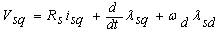
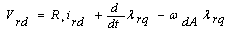
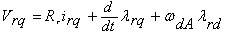
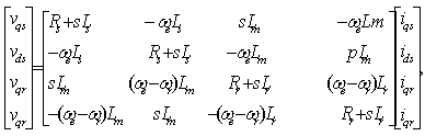
- In this study, the mathematical model of the system consists of space vector PWM voltage source inverter, induction motor, direct flux and the torque control. An induction motor model to predict the voltage required achieving a desired output torque is given in[16]. Fig.1.shows the power circuit of the 3-phase induction motor and Fig.2. shows the equivalent circuit used for obtaining the mathematical model of the IM.
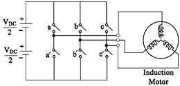 | Figure 1. Power circuit connection diagram for the IM |
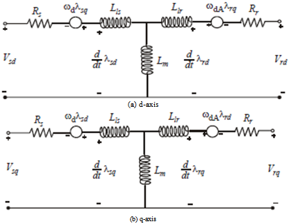 | Figure 2. Equivalent circuit of induction motor in d - q frame |
 | (1) |
 | (2) |
 | (3) |
 | (4) |
 | (5) |
 | (6) |
 | (7) |
 | (8) |
 | (9) |
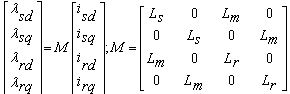
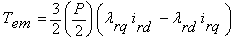
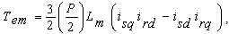
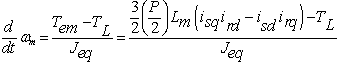
 is angular speed, Tem is electromagnetic torque, TL is load torque,
  is equivalent moment of inertia, Lm is mutual inductance, Lr is rotor inductance, Ls is stator inductance, and VDC is dc voltage .
3. Particle Swarm Optimization
3.1. Background of Particle Swarm Optimization
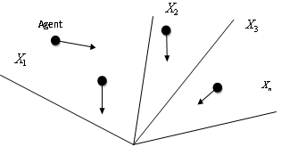
- Natural creatures sometimes behave as a swarm. One of the main streams of artificial life researches is to examine how natural creatures behave as a swarm and reconfigure the swarm models inside a computer. Swarm behavior can be modeled with a few simple rules. School of fishes and swarm of birds can be modeled with such simple models. According to the research results for a flock of birds, birds find food by flocking (not by each individual). The observation leads the assumption that all information is shared inside flocking. PSO is basically developed through simulation of bird flocking in two-dimension space). The position of each agent is represented by XY axis position and also the velocity is expressed by vx (the velocity of X axis) and vy (the velocity of Y axis). Modification of the agent position is realized by the position and velocity information. Bird flocking optimizes a certain objective function. Each agent knows its best value so far (pbest) and its XY position. This information represents the personal experiences o each agent. Moreover, each agent knows the best value so for in the group (gbest) among (pbests). Namely, each agent tries to modify its position using the following information: the current positions (x, y), the current velocities (vx, vy), the distance between the current position and pbest, the distance between the current position and gbest. This modification can be represented by the concept of velocity. Velocity of each agent can be modified by the following equation (10,11)
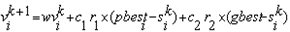 | (10) |
 | (11) |
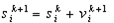 | (12) |
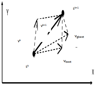 | Figure 3. Concept of modification of a searching point by PSO |
 | Figure 4. Searching concept with agents in a solution space by PSO |
 and velocities
  of each agent are usually generated randomly within the allowable range. The current searching point is set to pbest for each agent. The best-evaluated value of pbest is set to gbest and the agent number with the best value is stored.Step 2: Evaluation of searching point of each agentThe objective function value is calculated for each agent. If the value is better than the current pbest of the agent, the pbest value is replaced by the current value. If the best value of pbest is better than the current gbest, gbest is replaced by the best value and the agent number with the best value is stored.Step 3: Modification of each searching pointThe current searching point of each agent is changed using (10)-(12)Step 4: Checking the exit condition such as maximum number of iterationThe current iteration number reaches the predetermined maximum iteration number or any other stopping condition (desired accuracy) is reached, then exit. Otherwise, go to step 2.
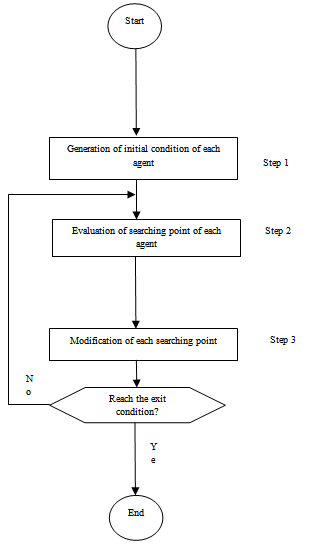 | Figure 5. General flow chart of PSO |
3.2. Parameter Selection of PSO
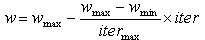
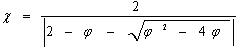
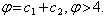
- The role of the inertia weight w in Equation (10) is considered critical for the PSO's convergence behavior. The inertia weight is employed to control the impact of the previous history of the velocities on the current one. Accordingly, the parameter w regulates the trade-off between the global (wide-ranging) and local (nearby) exploration abilities of the swarm. A large inertia weight facilitates global exploration (searching new areas), while a small one tends to facilitates local exploration, i.e., fine-tuning the current searching area. A suitable value of inertia weight w usually provides balance between global and local exploration abilities and consequently results in reduction of the number of iterations required to locate the optimum solution. Initially, the inertia weight was constant. However, experimental results indicated that it is better to initially set the inertia to large value, in order to promote global exploration of the searching space, and gradually decrease it to get more refined solutions. Thus, an initial value around 1.2 and a gradual decline towards 0 can be considered as good choice for w.The parameters c1 and c2, in Equation (10), are not critical for PSO's convergence. However, proper fine-tuning may result in faster convergence and alleviation of local minima. An extended study of the acceleration parameter, indicates that c1 = c2 = 0.5 might provide even better results. Recent work reports that it might be even better to choose a larger cognitive parameter, c1 than a social parameter, c2 but with c1 +c2 ≤ 4.The parameters r1 and r2 are used to maintain the diversity of the population, and they are uniformly distributed in the range[0, 1].The constriction factor χ is a way of choosing the values of w, c1, and c2 so that convergence is ensured. A modified velocity update equation, corresponding to one of several constriction factor is presented in equation (13).
 | (13) |
 | (14) |
 As[14] study the performance of PSO using the constriction factor. Their results indicated that using the constriction factor usually resulted in a better rate of convergence.
4. Realization of PSO-PI Controller Tuning Optimal Parameters
4.1. Proposed PSO-PI Controller
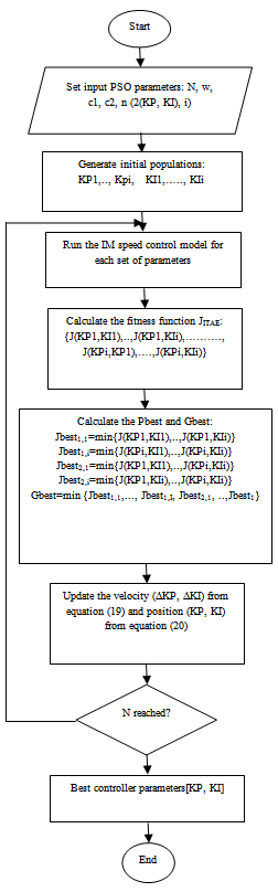
- In this paper the particle swarm optimization algorithms (PSO) (each particle contains two members P and I) mean that the search space has two dimension and particles that must 'fly' in a two dimensional space, (PSO are applied to search globally optimal parameters of PI)[17]. PSO Algorithms are used to find the optimal parameters of IM speed control system. The structure of the PI controller with PSO algorithm is shown in Figure 6.The conventional control system performance behaves poorly in characteristics and even it becomes unstable, when improper values of the controller tuning constants are used. The proposed PSO technique has the feature of tuning at every time, the particles are assumed new positions, they are ensured to update the best particle by comparing the costs corresponding to these positions with the previously selected best particle cost[17]. The flowchart shows the parameters selection using PSO-PI, see Figure 7.
 | Figure 6. Optimal PI controller with PSO algorithm |
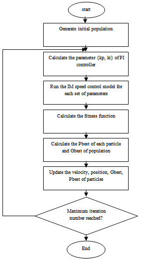 | Figure 7. The Flowchart of the PSO-PI Control System technique |
4.2. Fitness Function
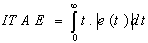
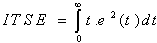
- In PI controller design methods, the most common performance criteria are integrated absolute error (IAE), the integrated of time weight square error (ITSE), integrated of squared error (ISE) and integrated of time weight absolute error (ITAE) that can be evaluated analytically in the frequency domain[18, 20]. These four integral performance criteria in the frequency domain have their own advantage and disadvantages. For example, disadvantage of the IAE and ISE criteria is that its minimization can result in a response with relatively small overshoot but a long settling time because the ISE performance criterion weights all errors equally independent of time. Although the ITSE performance criterion can overcome the disadvantage of the ISE criterion, the derivation processes of the analytical formula are complex and time-consuming[18,19]. The IAE, ISE, ITAE and ITSE performance criterion formulas are as follows:
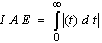 | (15) |
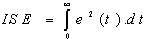 | (16) |
 | (17) |
 | (18) |
5. PSO –PI Controller Selection
5.1. PSO –PI Controller
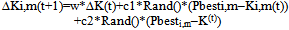
- The control system parameters (kp, ki),for two-variable optimization problem, a flock of particles are put into the two-dimensional search space with randomly chosen velocities (∆Ki,1, ∆Kii,2) and positions (Ki,1, Ki,2) knowing their best values so far (pbest), and the positions in the two-dimensional space. The velocity of each particle (∆Ki,1,∆Ki,2), adjusted according to its own flying experience and the other particle's flying experience. For example; the i-th particle is represented as Ki=(Ki,1,Ki,2). In the two-dimensional space, the best previous position of the i-th particle is recorded and represented as Pbesti=(Pbesti, 1 ,Pbesti,2).The best particle among all of the particles in the group is gbestd , the velocity for particle i is represented as ∆Ki =(∆Ki,1,∆Ki,2). After finding the two best values, the particle updates its velocity and position, and then each particle can be calculated using the current velocity and the distance from Pbest to gbest as shown in the following formulas[21,22,23]:
 | (19) |
5.2. PSO-PI Controller Parameter Selection
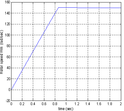
- To control the speed of an induction motor at 150 rad/sec, the following PSO parameters are used to verify the performance of the PSO-PI controller parameters shown in table 1.
|
|
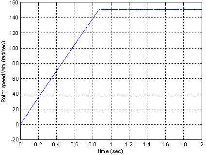 | Figure 8. Speed in case of PSO-PI (TL=2N.m at t=0sec) |
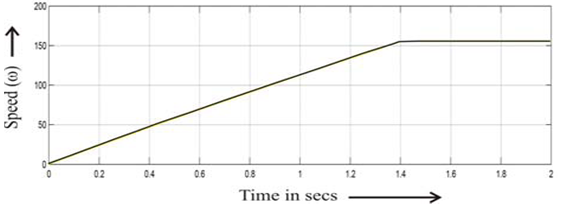 | Figure 9. Speed in case of Mamdani control strategy[24] |
 | Figure 10. Speed in case of PSO-PI (TL=200N.m at t=1.2sec) |
6. Conclusions
- In this paper, a sincere attempt is made to reduce the settling time of the responses and make the speed of response very fast by designing an efficient controller using PSO-PI control strategy. Here, we have control strategy for the speed control of IM, which has yielded excellent results compared to the others mentioned in the literature survey above. The results of our work have showed a very low transient response and a non-oscillating steady state response with excellent stabilization.
APPENDIX
- A1. Squirrel Cage Induction Motor (SCIM) specs:50 HP, 1800 rpm, 460 V, 60 Hz. 3-Phase, 2 pair of poles, Squirrel Cage type IM, Rs=0.087 Ω, Ls=0.8 mH, Rr=0.228 Ω, Lr=0.8 mH, Lm=34.7 H, J=1.662 kg.m^2.A2.The Flowchart of the PSO-PI Control System technique