Kh. Belgacem 1, A. Mezouar 1, A. Massoum 2
1Department of Electrical Engineering, Faculty of sciences Engineering Tahar Moulay University, SAIDA, Algeria
2Department of Electrical Engineering, Faculty of sciences Engineering Djillali Liabes University, SBA, Algeria
Correspondence to: Kh. Belgacem , Department of Electrical Engineering, Faculty of sciences Engineering Tahar Moulay University, SAIDA, Algeria.
| Email: |  |
Copyright © 2012 Scientific & Academic Publishing. All Rights Reserved.
Abstract
This paper deals with a variable speed device to produce electrical energy on a power network, based on a doubly-fed induction machine used in generating mode (DFIG). This device is intended to equip nacelles of wind turbines. First, a mathematical model of the machine written in an appropriate d-q reference frame is established to investigate simulations. In order to control the power flowing between the stator of the DFIG and the power network, a control law is synthesized using two types of controllers: PI and SMC (Sliding Mode Control). Their performances are compared in terms of power reference tracking, response to sudden speed variations, sensitivity to perturbations and robustness against machine parameters variations.
Keywords:
Doubly fed induction generator, Variable speed wind turbine, Power control, PI Controller, Sliding Mode Controller
Cite this paper: Kh. Belgacem , A. Mezouar , A. Massoum , Sliding Mode Control of a Doubly-fed Induction Generator for Wind Energy Conversion, International Journal of Energy Engineering, Vol. 3 No. 1, 2013, pp. 30-36. doi: 10.5923/j.ijee.20130301.05.
1. Introduction
DFIG, has recently received much attention as one of preferred technology for wind power generation. Compared to a full rated converter system, the use of DFIG in a wind turbine offers many advantages, such as reduction of inverter cost, the potential to control torque and a slight increase in efficiency of wind energy extraction.The wind turbines variable-speed operation has been used for many reasons. Among these are the decrease of the stresses on the mechanical structure, acoustic noise reduction and the possibility of active and reactive power control[1]. Most of the major wind turbine manufacturers are developing new larger wind turbines in the 3–6-MW range. These large wind turbines are all based on variable speed operation with pitch control using a direct-driven synchronous generator (without gear box) or a doubly fed induction generator (DFIG). The main advantage of the DFIG is that the power electronics equipment only carries a fraction of the total power (20–30%)[5]; this means that the losses in the power electronics converters, as well as the costs, are reduced. Motivated by the reason above, this paper provides a study of the dynamics of the grid connected wind turbine with DFIG.The paper starts with development of a wind turbine model with DFIG in Matlab/Simulink, followed by simulations of the model during grid disturbance. In the simulation, the ability of the DFIG to recover terminal voltage after grid disturbance is presented.This paper presents a control method for the machine inverter in order to regulate the active and reactive power exchanged between the machine and the grid. The active power is controlled in order to be adapted to the wind speed in a wind energy conversion system and the reactive power control allows to get a unitary power factor between the stator and the grid. Such an approach does not manage easily the compromise between dynamic performances and robustness or between dynamic performances and the generator energy cost. These compromises cannot easily be respected with classical PI controllers proposed inmost DFIG control schemes. Moreover, if the controllers have bad performances in systems with DFIG such as wind energy conversion, the quality and the quantity of the generated power can be affected. It is then proposed to study the Sliding Mode Control (SMC). The two controllers are compared and results are discussed, the objective is to show that complex controllers as (SMC) can improve performances of doubly-fed induction generators in terms of reference tracking, sensibility to perturbations and parameters variations.
2. Model of the Doubly-Fed Induction Generator
2.1. Modelling of the Wind Turbine and Gearbox
The aerodynamic power, which is converted by a wind turbine,  is dependent on the power coefficient
 . It is given by
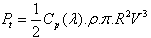 | (1) |
Where  is the air density,
  is the blade length and
  is the wind velocity. The turbine torque is the ratio of the output power to the shaft speed
  :
:  The turbine is normally coupled to the generator shaft through a gearbox whose gear ratio G is chosen in order to set the generator shaft speed within a desired speed range. Neglecting the transmission losses, the torque and shaft speed of the wind turbine, referred to the generator side of the gearbox, are given by:
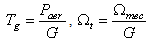 | (2) |
Where  is the driving torque of the generator and
  is the generator shaft speed, respectively. A wind turbine can only convert just a certain percentage of the captured wind power. This percentage is represented by
  which is function of the wind speed, the turbine speed and the pith angle of specific wind turbine blades[6],[7]. Although this equation seems simple,
  is dependent on the ratio
  between the turbine angular velocity
  and the wind speed
 . This ratio is called the tip speed ratio:
 | (3) |
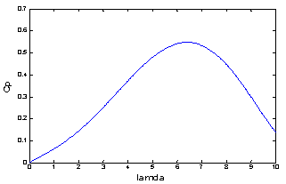 | Figure 1. Power coefficient for the wind turbine model |
A typical relationship between  and
and  is shown in Fig. 1. It is clear from this figure that there is a value of
  for which
  is maximum and that maximizes the power for a given wind speed. The peak power for each wind speed occurs at the point where
  is maximized. To maximize the generated power[8],[9], it is therefore desirable for the generator to have a power characteristic that will follow the maximum
  line.
line.
2.2. Modelling of the DFIG
The classical electrical equations of the DFIG in the PARK frame are written as follows[10]: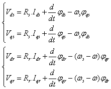 | (4) |
Where  and
and  are, respectively, the stator and rotor phase resistances,
  is the electrical speed and
  is the pair pole number.The stator and rotor flux can be expressed as
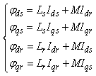 | (5) |
Where ,
, ,
,  , and
, and  are, respectively, the direct and quadrate stator and rotor currents.The active and reactive powers at the stator, the rotor as well as those provide for grid are defined as[11]:
 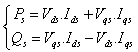 | (6) |
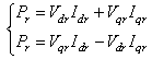 | (7) |
The electromagnetic torque is expressed as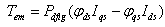 | (8) |
3. Control Strategy of the DFIG
3.1. Decoupling of the Active and Reactive Powers
When the DFIG is connected to an existing grid, this connection must be established in the following three steps. The first step is the synchronisation of the stator voltages with the grid voltages, which are used as a reference. The second step is the stator connection to this grid. After that, the connection can be effectively established. Once this connection is achieved, the third step is the regulation of the transit of the power between the DFIG and the grid A  reference-frame synchronized with the stator flux is employed[12]. By setting the quadratic component of the stator to the null value as follows:
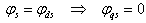 | (9) |
Then the torque is simplified as indicated below: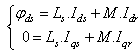 | (10) |
The electromagnetic torque, and subsequently the active power, will only depend on the rotor current along the  axis. By neglecting the stator resistance
 | (11) |
Using Equations (4), (5) and (9) the stator active and reactive power can then be expressed only versus these rotor currents as: 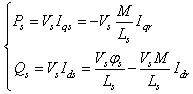 | (12) |
4. Controllers Synthesis
4.1. PI Regulator Synthesis
This controller is simple to elaborate. Fig. 2 shows the block diagram of the system implemented with this controller. The terms  and
and  represent respectively the proportional and integral gains.
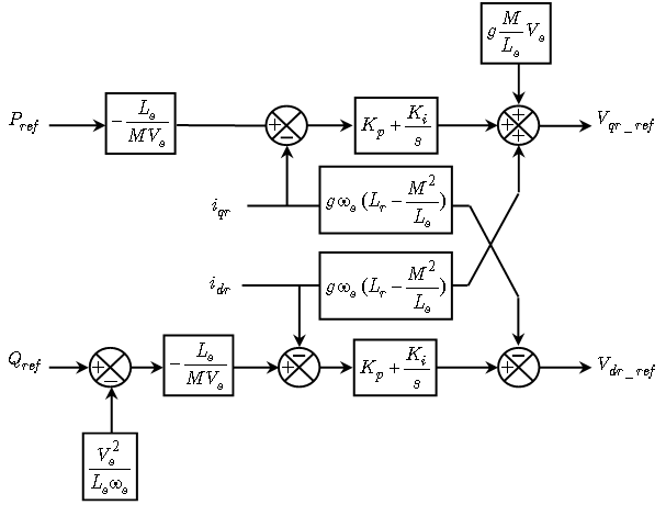 | Figure 2. Configuration of the power control of the DFIG with PI |
4.2. Design Sliding Mode (SMC)
The rotor currents (which are linked to active and reactive powers by equation (12) have to track appropriate current references, so, a sliding mode control based on the above Park reference frame is used. The sliding surfaces representing the error between the measured and references rotor currents are given by this relation[6]: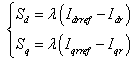 | (13) |
 and
and  will be the two components of the control vector used to constraint the system to converge to
  .The control vector
  is obtain by imposing
  , so the equivalent control components are given by the following relation[7]:
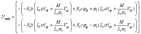 | (14) |
To obtain good performances, dynamic and commutations around the surfaces, the control vector is imposed as follows: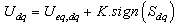 | (15) |
The sliding mode will exist only if the following condition is met: | (16) |
The block-diagram of the variable structure control of the DFIG is presented on Fig. 3. The stator active and reactive powers are controlled.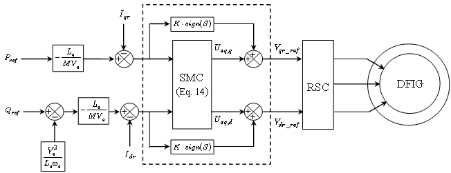 | Figure 3. Configuration of the power control of the DFIG with SMC |
5. Results and Discussion
In this section, we have chosen to compare the performances of the DFIG with two different linear and non linear controllers. The proportional–integral will be first tested and will be the reference compared to the other: Sliding Mode Control. This controller is simple to elaborate. Fig. 2 shows the block diagram of the system implemented with this controller. The terms  and
and  represent respectively the proportional and integral gains. The regulator terms are calculated with a pole-compensation method. In this section some simulative resultants obtained to using the MATLAB/Simulink platform are presented in order to highlight the robustness of the proposed solution for decoupled stator active and reactive power control. To guarantee stable operation and to enable independent control active and reactive power of the DFIG, a model based to using the PI and SMC controllers are developed using the dynamic model equations mentioned above. A block diagram is shown in Fig 3. In order to provide a decoupled control of the stator active power
  and reactive power
  of the DFIG by means of the stator current regulation with SMC, the
  components of the rotor currents are defined in the stator flux oriented reference frame. The main is to represent
  and
and  as functions of the individual stator current components. The desired
  and
and  can determine the reference stator currents, which us allows to calculate the components of the reference rotor voltage, as well as the control by technique PWM is realised for the inverter control which feeds the rotor through a converter. For guarantee a drive of the DFIG around its speed of synchronism by carrying out a speed regulation.
5.1. Reference Tracking
The first test investigated to compare the two controllers is reference tracking by applying stator active and reactive power steps (respectively  and
and  ) at
) at  to the DFIG, while the machine’s speed is maintained constant at
  . The machine is considered as working over ideal conditions (no perturbations and no parameters variations), The results for the indirect control mode are presented in Fig. 4. In this control mode, transient oscillations due to the coupling terms between the two axes and static error appear on active and reactive powers. This is inherent to the adopted control mode: the feedback signal of the controller is calculated using rotor currents and considering that stator resistance is neglected. It can be seen that transient oscillations amplitude are minimized with PI controller which SMC have better rejection of perturbations.
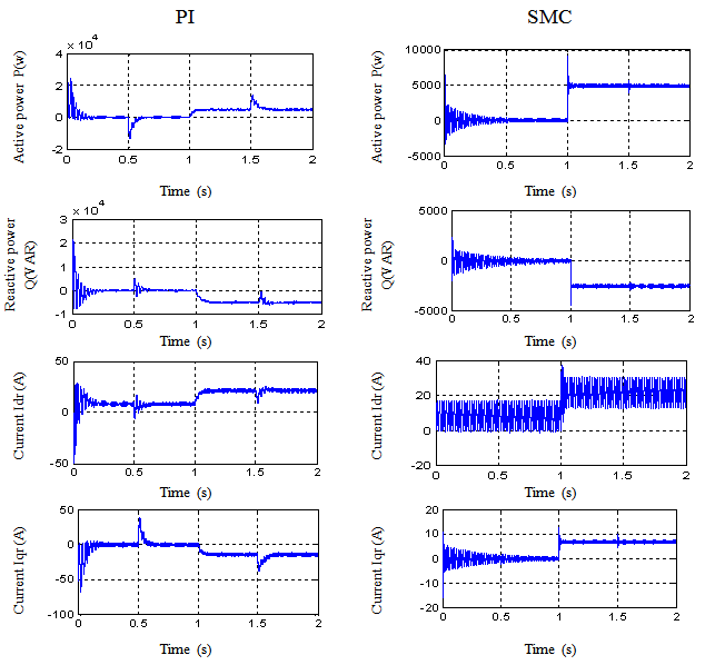
5.2. Sensibility to Perturbations
The aim of this test is to analyze the influence of a speed variation of the DFIG on active and reactive powers. The active and reactive power references are maintained to  and
and  and at
  the speed varies from
  to
to  . The results and at time= 1.5 s the speed varies also from
  to
to  . The results are shown in Fig. 5. This figure shows the limits of the PI controller which is only based on the machine’s parameters and does not take into account any disturbances. Indeed, for this controller, a speed variation induces an important variation of the active and reactive powers (20% for active power and 10% for reactive power). The SMC controller includes the presence of perturbations in its synthesis, so it shows better disturbance rejection than PI controller (11% of active power variation and 6% of reactive power variation). This rejection is still not perfect because the synthesis of the controller includes parameters which have no explicit influence on its behaviour and are difficult to be tuned. The SMC controller has a nearly perfect speed disturbance rejection, indeed; only small power variations can be observed (less than 1% for active and reactive powers). This result is interesting for wind energy applications to ensure stability and quality of the generated power when the speed is varying.
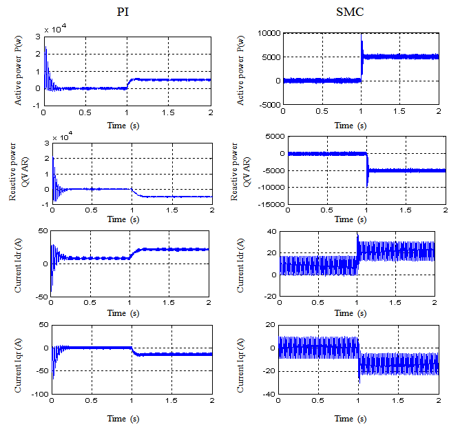 | Figure 4. Reference tracking (indirect control) |
 | Figure 5. Effect of a speed variation (indirect control) |
6. Conclusions
In this paper, we have presented a complete system to produce electrical energy with a doubly-fed induction generator by the way of a wind turbine. The studied device is constituted of a DFIG with the stator directly connected to the grid and the rotor connected to the grid by the way of two converters (machine inverter and grid inverter). The control of the machine inverter has been presented first in order to regulate the active and reactive powers exchanged between the machine and the grid. Two different controllers are synthesized and compared. When the DFIG is in ideal conditions (no parameters variations and no disturbances), the performances of the two controllers are similar. When the machine’s speed is modified (witch represents a perturbation for the system), the impact on the active and reactive powers values is important for PI controller whereas it is almost non-existent for SMC controller one.
ACKNOWLEDGMENTS
The authors would like to acknowledge the financial support of the Algeria's Ministry of Higher Education and Scientific Research, under CNEPRU project: J02036 2010 0005.
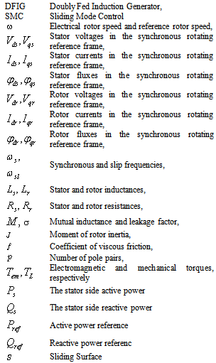
Nomenclature
Appendix: Parameters
DFIG nominal parameters TURBINE parameters
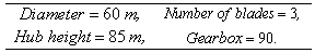 (DFIG+TURBINE) parameters
References
| [1] | F. Poitiers, T. Bouaouiche, M. Machmoum “Advanced control of a doubly-fed induction generator for wind energy conversion” Electric Power Systems Research 79 (2009) 1085–1096 |
| [2] | Aouzellag D, Ghedamsi K, Berkouk EM. “Modelling of doubly fed induction generator with variable speed wind for network power flow control”, JTEA’06, Tunis. |
| [3] | T.K.A. Brekken, N. Mohan, “Control of a doubly fed induction wind generator under unbalanced grid voltage conditions” , IEEE Transaction on Energy Conversion 22 (March (1)) (2007) 129–135. |
| [4] | L. Piegari, R. Rizzo, “ A control technique for doubly fed induction generators to solve flicker p roblems in wind power generation” International Power and Energy Conference, Putrajaya, Malaysia, 28 and 29 November 2006, pp. 19–23. |
| [5] | El Aimani Salma “Modélisation de différentes technologies d’éoliennes intégrées dans un réseau de moyenne tension” Doctorat Thesis L’EPLF, LEI Lausanne 2006. |
| [6] | A. Gaillard, P. Poure, S. Saadate, M. Machmoum “Variable Speed DFIG Wind Energy System for Power Generation and Harmonic Current Mitigation, Renewable Energy 34,2009, pp 1545-1553 |
| [7] | M. Hamerlain, T. Youssef, M. Belhocine, Switching on the derivative of control to reduce chatter, IEE Proceeding Control Theory and Applications, Vol.148, Issue 1, Jan |
 Abstract
 Reference
 Full-Text PDF
 Full-text HTML