H. Z. Hassan
Department of Mechanical Engineering, College of Engineering, Alfaisal University, PO Box 50927, Riyadh, 11533, KSA
Correspondence to: H. Z. Hassan , Department of Mechanical Engineering, College of Engineering, Alfaisal University, PO Box 50927, Riyadh, 11533, KSA.
| Email: |  |
Copyright © 2012 Scientific & Academic Publishing. All Rights Reserved.
Abstract
In this study, the operation and performance of a solar–powered adsorption based freezing unit under Egypt’s weather conditions is investigated. A dynamic simulation model is developed to simulate the cooling system considering the real variation of solar radiation, ambient temperature, and wind speed. Activated carbon and methanol are used as the working pair. Moreover, a 2m×1m flat plate solar collector is used to power the adsorption ice–maker. The freezer is studied under the climatic conditions of Cairo city, Egypt and in the June 23ed, 2012. It is found that the ice machine attains a coefficient of performance of 0.618. Furthermore, the adsorption cooling system produces daily ice of 27.82 kg at a temperature of -5 ℃ and from water at a source temperature of 25 ℃.
Keywords:
Solar Cooling, Adsorption , Modelling, Dynamic Simulation
Cite this paper: H. Z. Hassan , A Solar Powered Adsorption Freezer: A Case Study for Egypt’s Climate, International Journal of Energy Engineering, Vol. 3 No. 1, 2013, pp. 21-29. doi: 10.5923/j.ijee.20130301.04.
1. Introduction
Cold production (cooling, freezing, and air–conditioning) is an expensive industry which requires considerable amount of electrical energy. The rapid growth of economy, human prosperity, and propagation of the conventional air conditioning machines cause a shortage of grid–electricity especially during summer season. Approximately 10–20% of all the electricity produced in the whole world is consumed by various kinds of the refrigeration and air–conditioning machines[1]. However, the development of refrigeration technology presents the thermally driven cold production systems. These systems are considered good alternative for the electricity powered vapor compression machines in terms of electricity consumption as well as environmental issues. Recently, the booming progress in the field of green cooling technology offers cooling systems which can be powered by renewable and green energy sources like solar energy. Except nuclear, geothermal, and tidal energy, all of the global energy sources originate from the solar radiation. The total solar radiation transmitted to the earth's diametric plane area is approximately 1.74 × 10¹⁷ W[2],[3]. However, the amount of actual incoming solar radiation to the earth's surface is affected by the reflection and scattering, and absorption by the earth's atmosphere[4]. Therefore, about 47.2 % of actual incoming solar radiation is absorbed by the earth's surface[5]. This amount is larger than the energy requirements of the world in year 2008. Only 1% of this energy, when converted at an efficiency of 10% would generate approximately five times of the world's total requirements of energy. In another perspective, the sun offers more energy than the human race uses in a whole year in just less than two hours. From this perspective, the problem of energy is not due to shortage of sources, but it is due to the lack of a cost-effective technology that can be used to convert the abundant energy lies around us into usable forms[6].In Egypt at least 32 % of the electrical energy used by the domestic sector is for air–conditioning[7]. Furthermore, primary energy requirement in Egypt increases by 2.6% every year[8]. The growth of electrical energy demand in the expanding towns and industries exceeds the growth of the available power. Therefore, it is important for local policies to be directed towards replacing traditional refrigeration systems with environmentally friendly technologies that can be operated by sustainable, continuous supply, and clean sources of energy in order to protect the environment and preserve energy sources. In fact, Egypt enjoys an abundant amount of solar radiation which is much more than other renewable energy sources. This makes solar powered cooling systems attractive green cooling technology in Egypt. Particularly, the excellent matching between the high availability of sunshine and the peaks of requirements in cold and refrigeration needs. Moreover, solar refrigeration is a suitable alternative for people who live in remote areas with insufficient electricity.One of these promising thermally driven cooling technologies which can be powered by solar radiation is the adsorption refrigeration technology[9]. This type of cold producing system operates with environmentally benign refrigerants which have zero ozone depleting potential. The wide range of heat source temperatures that can be used, 50℃ to 600℃, and the low operation and maintenances costs make these systems highly attractive[10]. Many researches and studies on the solar adsorption cooling system have been widely investigated[11–14]. Moreover, experimental work, transient simulation, different working pairs, and system designs were introduced[15–20]. While going through the material we find that, solar adsorption cooling system has its own merits and demerits in application depending on the application area, the driving heat source temperature, and the climatic conditions at the location of the application. To the best of our knowledge, there is not any published study that has been devoted to study the performance of such cooling system under the Egypt climatic conditions. From this motivation, this work is devoted to investigate the operation and performance of a solar powered adsorption freezer under weather conditions of Egypt.
2. The Solar Adsorption Cooling System
The solar adsorption cooling system is similar to the traditional vapour compression refrigeration system with the electricity driven compressor is replaced with a thermal powered one, Figure 1. The adsorption container is integrated with a flat plate solar collector and contains a porous adsorbent medium. The solid adsorbent has the affinity to adsorb the refrigerant vapour[16]. Furthermore, the thermodynamic cycle of the adsorption refrigeration system is illustrated on Clapeyron diagram, Figure 2. The cycle consists of four processes; pressurization preheating process at a constant concentration (isosteric heating process 1Õ2), desorption at constant pressure (isobaric heating process 2Õ3), depressurization at constant concentration (isosteric cooling process 3Õ4), and adsorption at constant pressure (isobaric cooling process 4Õ1)[16].During the daytime period, the adsorption reactor is isolated from both the condenser and the evaporator by valves c and e and is completely saturated with the refrigerant. The pressure inside the reactor initially equals the evaporator pressure and its temperature is uniform and equals the ambient temperature
 , state 1 on Figure 2. The pressure and the temperature inside the bed increase when the reactor is heated by the solar radiation. This process continues till the pressure approaches
  at state 2. At the end of this process valve c opens to allow the refrigerant vapour desorbed from the bed to flow towards the condenser while the adsorption reactor is still being heated by the solar radiation. The pressure inside the bed is fixed at the condenser pressure while the temperature continues to increase. Furthermore, the refrigerant content inside the reactor continues to decrease as more adsorbate is being freed from the reactor. The condensed refrigerant is then collected and stored in the refrigerant storage tank[16]. When the adsorbate temperature reaches the maximum allowed value
  at state 3 or the incident solar radiation starts to decrease at the end of the nocturnal period, valve c is closed in order to start the bed cooling process 3Õ4. This process takes place when the glass cover of the flat plate solar collector is opened to allow convective and radiative heat transfer to the ambient. Both temperature and pressure drop till the pressure reaches the evaporator pressure at state 4. At this point, valve t is opened to allow the liquid refrigerant, which is previously stored in the storage tank, to pass through the expansion device. Moreover, valve e opens and the refrigerant vapour flows towards the reactor. This process consists of the refrigerant adsorption within the reactor in parallel with the production of cooling effect inside the evaporator. The reactor is being cooled during this period in order to remove the heat of adsorption. The evaporation-adsorption process takes place at the constant evaporator pressure and continues till the adsorption bed retains its higher cycle isoster at state 1[16].
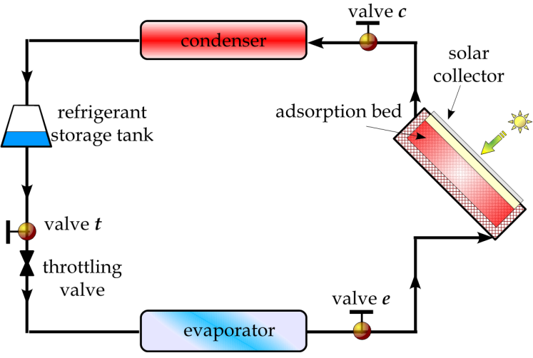 | Figure 1. Schematic diagram of the solar adsorption cooling system[16] |
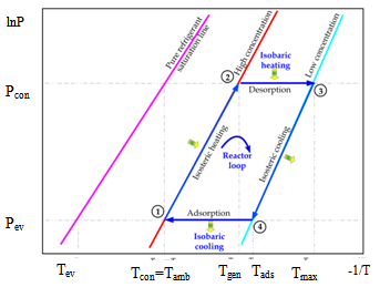 | Figure 2. The thermodynamic adsorption cooling cycle. |
3. The Adsorption Model
The adsorbate concentration ratio x is the amount of adsorbate per unit mass of the adsorbent. The Dubinin–Astakhov (D–A) equation is used to calculate as follows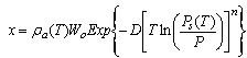 | (1) |
The constant  is the maximum adsorption capacity and
 ,
,  are constants which depend on the adsorbate–adsorbent pair.
  and
and are the adsorbate density and the saturation pressure corresponding to the bed temperature. The adsorbate volume fraction
  is the adsorbate volume per unit volume of the adsorbent material and is given by
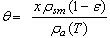 | (2) |
Where,  is the adsorbent density, and
  is its porosity. The isosteric heat per unit mass of adsorbate
  is calculated from Clapeyron equation
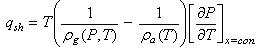 | (3) |
Where,  and
and  are the density of the gas and the adsorbate refrigerant phases, respectively.
4. Mass and Energy Balance
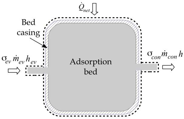 | Figure 3. The adsorption reactor control volume |
The mass balance equation for the adsorption reactor shown in Figure 3 can be expressed as follows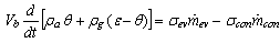 | (4) |
Where,  is the adsorption bed volume,
  and
and  are the refrigerant mass flow rate from the evaporator and to the condenser, respectively. The evaporator flag
  equals 1 during the adsorption process and 0 otherwise. The condenser flag
  equals 1 during the desorption process and 0 otherwise. The energy balance equation can be written as:
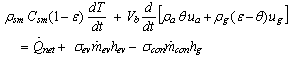 | (5) |
Where,  is the porous media specific heat, and
  and
and  are the specific enthalpies of the refrigerant vapour from the evaporator and to the condenser, respectively. The net heat transfer rate to or from the adsorption bed
  is calculated from the solar collector energy balance.
5. The Solar Collector Energy Balance
The mathematical model of the flat plate solar collector is based on the energy balance for the collector absorber plate. The total solar radiation  incident on the flat plate solar collector has three components: direct beam solar radiation
 , ground diffuse radiation
 , and sky reflection radiation
 . However, this amount of radiation is reduced by optical losses of the flat plate solar collector. The actual amount of radiation from the sun that is availiable for the collector
  is given by
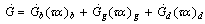 | (5) |
Where,  ,
, , and
, and  are the transmittance–absorptance product for beam, ground, and sky diffuse radiation, respectively[21]. The useful amount of radiation
  that goes to the adsorption bed is reduced by heat losses to the ambient
 . For a collector of plate area
 , the useful heat
  is calculated from the following equation
 | (6) |
Heat loss from the solar collector is expressed in terms of the overall heat transfer loss coefficient as follows
 | (7) |
Heat transfer from the lateral and bottom surfaces of the solar collector are negligible compared with heat losses from the top surface of the collector. The heat transfer coefficient is calculated from method presented by[22] and is discussed by[21] as follows | (8) |
where,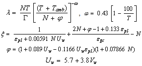 where,
  is the absorber plate emissivity,
  is the glass cover emissivity,
  is the number of glass covers,
  is the Stefan–Boltzmann constant. The wind convection coefficient
  is calculated in terms of the wind velocity
  from the following equation[23]
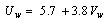 | (9) |
When the collector flat plate solar collector glass cover is opened during the isosteric cooling and the adsorption processes, the overall heat transfer coefficient is given by | (10) |
6. The Condenser and the Evaporator
The rate of heat removal at the condenser is given by | (11) |
Where,  is the specific enthalpy of the saturated refrigerant liquid at the ambient temperature. Therefore, the total heat removed at the condenser side is given by:
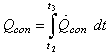 | (12) |
The cooling rate in the evaporator can be expressed by | (13) |
The cooling effect at the evaporator is given by: | (14) |
7. System Performance Parameters
The coefficient of performance of the adsorption cooling system  is given by
 | (15) |
The total amount of heat absorbed by the adsorption reactor during the preheating and the generation process  is calculated from
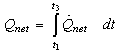 | (16) |
The cooling capacity  of the system is the rate at which cooling effect is produced and is given by
 | (17) |
The effective refrigerant mass  is the total mass of the desorbed refrigerant from the adsorption reactor which is circulated through the condenser and the evaporator. This refrigerant mass is responsible for providing the cooling effect inside the evaporator and is given by the following equation
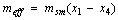 | (18) |
The total amount of ice production  at a temperature of
  from initial temperature of
  is given in kg/cycle by
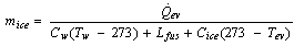 | (19) |
Where,  ,
,  , and
, and  are the specific heat of water, the latent heat of ice fusion, and the ice specific heat of ice respectively.
8. The Case Investigated
The case investigated in the present study is a cooling system which is used as an ice–maker with an evaporator temperature of -5℃. The freezer works under Egypt’s weather conditions and uses activated carbon–methanol as the working pair. The condensation temperature is set to 40 ℃ and the maximum cycle temperature is set to 130℃. The liquid and vapour thermodynamic properties of methanol have been calculated from the methanol equation of state reported by the IUPAC[24]. Furthermore, the flat plate solar collector is 2m × 1m surface area and has two glass covers and is placed at a tilt angle of 30° and is facing to the south. The total mass of the charcoal within the bed is 50 kg with a total porosity of 0.75. The time variations of the incident solar radiation, the real ambient temperature, and the real wind speed are taken in consideration. The selected location is Cairo city (latitude 30.04 °N, longitude 31.23 °E) and the system is considered to operate a full cooling cycle which starts at the sunrise time of June 23ed, 2012. Moreover, the real hourly temperature and wind speed variations for the location under consideration during the specified operational period are taken from the historical records[25].
9. Results and Discussions
Based on the developed dynamic simulation model and the case study parameters, a computer program was constructed in order to simulate the adsorption chiller. The water chilling system, under the climatic conditions associated with the location and time in the year under consideration, is found to acquire a cooling COP of 0.618. Other performance parameters obtained are 255.6 W and 5.11 W/kg for the cooling capacity and the specific cooling power of the system, respectively. The refrigeration effect produced inside the evaporator during is estimated to 12.49 MJ. This cooling effect corresponds to a total daily ice production of 27.8 kg at -5 ℃ from water at a source temperature of 25 ℃. Therefore, every kg of activated carbon inside the adsorption reactor produces a daily ice mass of 0.556 kg of ice and at a temperature of -5 ℃. Furthermore, the total refrigerant mass in the system is estimated to 13.44 kg of methanol. About 82.85% of this mass, 11.13 kg is an effective mass which circulates in the condenser and the evaporator and produces the refrigeration effect.The sun rises at about 5.034 hour in the morning, which is the starting time of the cycle, with the daylight length of 13.93 h. The components of the solar radiation incident on the flat plate are illustrated in Figure 5. These include the direct irradiation, the sky diffuse irradiation, and the ground reflected solar radiation. It is noticed that, the total solar irradiation absorbed by the solar collector is reduced by the amount of the transmittance–absorptance product. The total available solar energy is found to be 24.18 MJ/m2. The solar collector uses about 58.6% of the total available solar energy along the operational cycle, 14.17 MJ/m2. Moreover, the amount of useful solar energy absorbed by the adsorption bed is found to be 10.11 MJ/m2.Figure 6 plots the ambient temperature changes during the cooling system working cycle. Also, Figure 7 gives the real recorded speed of wind at every hour within the operational time range. Both of the ambient temperature and the wind speed at any instance of time can be calculated by interpolating the corresponding given data.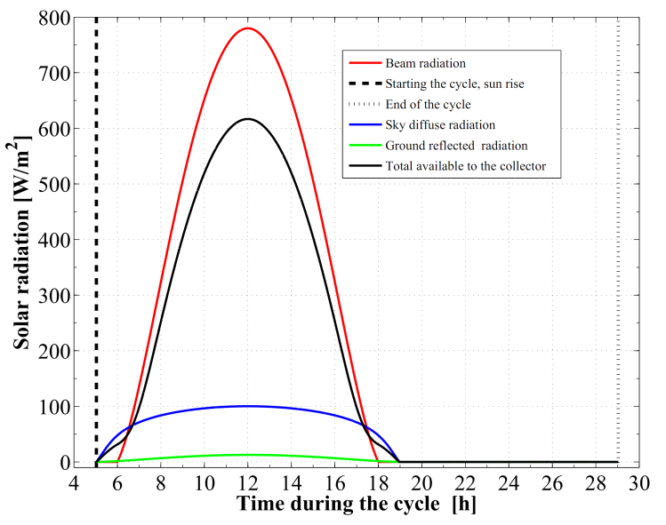 | Figure 5. Components of the incident solar radiation to the flat plate collector |
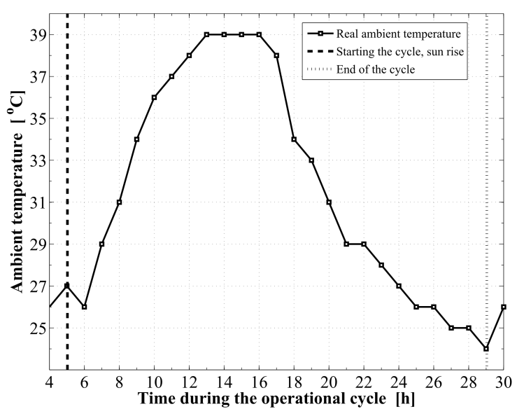 | Figure 6. The real ambient temperature profile during the operational cycle |
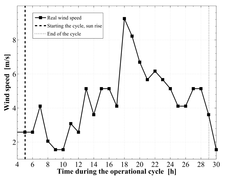 | Figure 7. The real wind speed profile during the operational cycle |
Figure 8 demonstrates the relation between the adsorption bed pressure and temperature for the cycle. The adsorption bed pressure rises from the evaporator pressure at 2.91 kPa to the highest cycle pressure at the condenser, 35.23 kPa, during the pre–heating process. It can be also seen that, the temperature in this process elevates from 27 ℃ to 76.63 ℃ at which the adsorbent starts the generation process. Then the bed pressure remains steady during the generation process till the maximum cycle temperature, 130 ℃, is reached. In process 3Õ4, the pressure and temperature values show a decreasing trend till the evaporator pressure is reached. The adsorption process starts at a temperature of 71.55 ℃. The time variations of the temperature and pressure inside the adsorption bed during a complete cycle of operation are shown in Figure 9 and Figure 10, respectively. During the isosteric heating phase, the adsorption reactor continues to absorb the continuously increasing solar radiation and a rapid increase in the adsorption bed temperature and pressure is noticed. At the end of this process, the pressure of the bed approaches the condenser pressure and the temperature reaches a value of 76.63 ℃. Due to the endothermic behaviour of the desorption process, the rate of temperature increase at beginning of this process is lower than the preheating process. Then, a dramatic decreasing rate in the reactor pressure and temperature takes place due to the cooling process that continues till the first half cycle ends. At beginning of the adsorption process, the bed temperature decreases slowly due to releasing the latent heat of adsorption. A nearly fixed temperature difference between the reactor and the ambient is maintained as a driving potential to reject the isosteric heat. Figure 11 demonstrates the time integration of the refrigerant mass desorbed from the reactor as well as adsorbed within the reactor. Figure 12 depicts the time integration of the heat absorbed by the adsorption reactor during the heating processes as well as the time integration of the waste heat rejected to the ambient during the cooling and the adsorption processes. By the end of the desorption process, the total amount of heat absorbed by the adsorption bed is found to be 10.1 MJ/m2. About 16.23 % of this heat is consumed in the preheating process. Whereas, the total amount of heat rejected by the adsorption bed is found to be 9.39 MJ/m2. About 12.53 % of this heat is rejected during the sensible cooling isosteric process.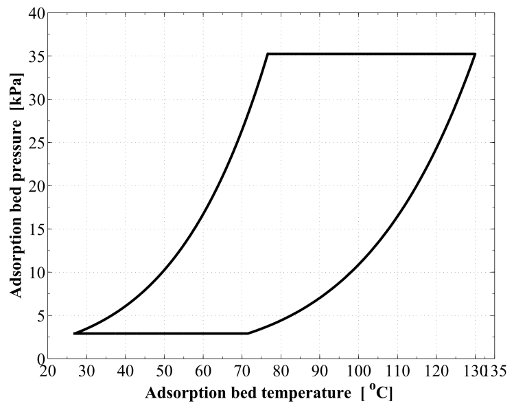 | Figure 8. P–T relation for the reactor along a complete cycle of operation |
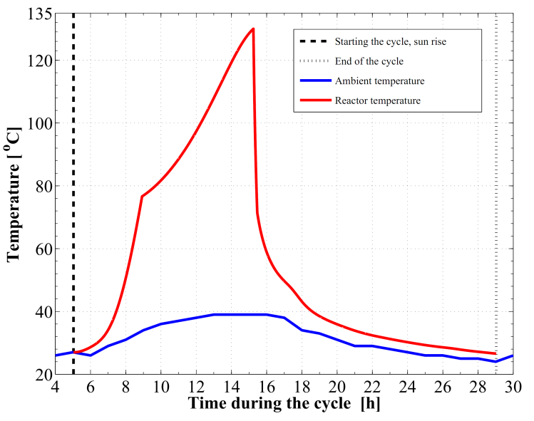 | Figure 9. Variation of the reactor temperature versus time |
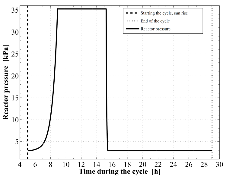 | Figure 10. Development of the reactor pressure versus time |
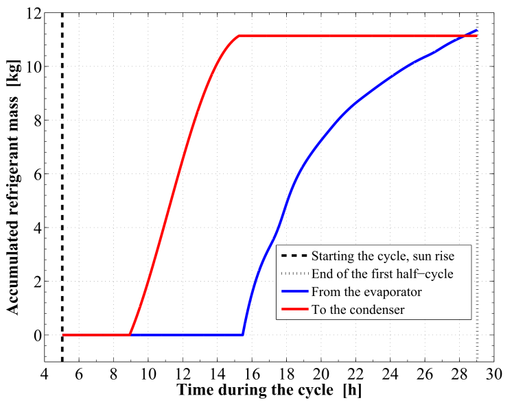 | Figure 11. Time integrated refrigerant vapor mass into and out of the reactor |
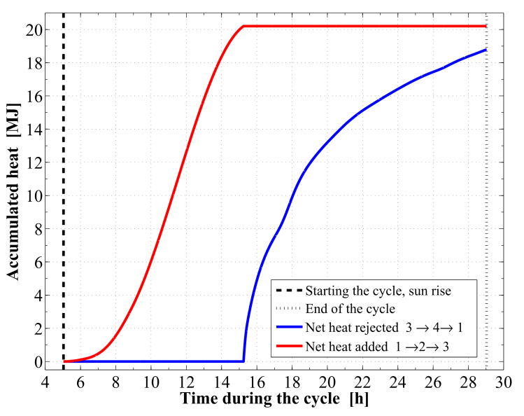 | Figure 12. Time integrated heat added to and rejected from the reactor |
10. Conclusions
In Egypt, the cconventional cooling and air conditioning systems consume large amounts of the electricity. Since the solar radiation is abundant in this area of the world, the solar powered cold producing systems are good alternative for the vapour compression machines. In the present work, an adsorption based freezer performance is investigated under Egypt’s weather conditions is investigated. Activated carbon and methanol are used as the working pair. It is found that, the freezer attains a coefficient of performance of 0.618 and produces daily ice of 27.82 kg at a temperature of -5 ℃ and from water at a source temperature of 25℃.
References
| [1] | Lucas L. Iir News. International journal of refrigeration 1998;21(2):87-8. |
| [2] | Oliver JE. The encyclopedia of world climatology (Encyclopedia of earth sciences series). Springer; 2005. |
| [3] | Hubbert MK. The energy resources of the earth. Energy and Power (A Scientific American Book) 1971:31-40. |
| [4] | Kiehl JT, Kevin ET. Earths annual global mean energy budget. Bulletin of the American Meteorological Society 1997;78(2):197-208. |
| [5] | Trenberth KE, John TF, Jeffrey K. Earth's global energy budget. Bulletin of the American Meteorological Society 2009;90(3):311-23. |
| [6] | Fisk MJ, Anderson HC. Introduction to solar technology. London: Addison-Wesley; 1982. |
| [7] | Elsafty A, Al-Daini A.J, Economical comparison between a solar-powered vapour absorption air-conditioning system and a vapour compression system in the Middle East Renewable Energy, Vol. 25 No. 4 pp. 569-583 ISSN: 0960-1481, 2002. |
| [8] | International Energy Agency (IEA). Key world energy statistics. 1st ed. Paris: OECD/IEA; 2010. |
| [9] | Hassan HZ, Mohamad AA. A review on solar cold production through absorption technology. Renewable & Sustainable Energy Reviews, 2012:16(7);5331–5348. |
| [10] | Wang RZ, Oliveira RG. Adsorption refrigeration e an efficient way to make good use of waste heat and solar energy. Progress in Energy and Combustion Science 2006;32(4): 424–58. |
| [11] | Critoph RE. Performance limitations of adsorption cycles for solar cooling. Solar Energy 1988;41(1):21–31. |
| [12] | Critoph RE, Vogel R. Possible adsorption pairs for use in solar cooling. International Journalof Ambient Energy 1986;7(4):183–90. |
| [13] | Jing H, Exell RHB. Simulation and sensitivity analysis of an intermittent solarpowered charcoal/methanol refrigerator. Renewable Energy 1994;4(1):133–49. |
| [14] | Ogueke NV, Anyanwu EE. Design improvements for a col-lector/generator/adsorber of a solid adsorption solar refrigerator. Renewable Energy 2008;33:2428–40. |
| [15] | Leite APF, Daguenet MD. Performance of a new solid ad-sorption ice maker with solarenergy regeneration. Energy Conversion and Management 2000;41(15):1625–47. |
| [16] | Hassan HZ, Mohamad AA. A review on solar–powered closed physisorption cooling systems. Renewable and Sustainable Energy Reviews, 16 (2012) 2516–2538. |
| [17] | Sumathy K, Zhongfu L. Experiments with solar–powered adsorption ice–maker. Renewable Energy 1999; 16(1–4):704–707. |
| [18] | Leite APF, Daguene M. Performance of a new solid adsorption ice maker with solar energy regeneration. Energy Conversion and Management 2000;41(15):1625–1647. |
| [19] | Anyanwu EE, Oteh UU, Ogueke NV. Simulation of a solid adsorption solar refrigeratorusing activated carbon/methanol adsorbent/refrigerant pair. Energy Conversion and Manage-ment 2001;42(7):899–915. |
| [20] | Li M, Wang RZ, Xu YX, Wu JY, Dieng AO. Experimental study on dynamic performance analysis of a flat–plate solar solid–adsorption refrigeration for ice maker. Renewable Energy 2002;27(2):211–221. |
| [21] | Duffie JA, Beckman WA. Solar Engineering of Thermal Processes. 3ed ed. New York: John Wiley & Sons; 2006. |
| [22] | Klein SA. Calculation of flat–plate collector loss coefficients. Solar Energy 1975;17:79–80. |
| [23] | Saraf GR , Hamad FAW. Optimum tilt angle for a flat plate solar collector. Energy Conversionand Management 1988; 28(2):185–191. |
| [24] | de Reuck KM. Methanol, international thermodynamic tables of the fluid state Vol. 12, Blackwell Science,1993. |
| [25] | http://www.wunderground.com/history/, WeatherUnder-ground, last visited on November 23, 2012. |
 Abstract
 Reference
 Full-Text PDF
 Full-text HTML