K. S. Sandhu 1, Sudhir Sharma 2
1Department of Electrical Engineering, National Institute of Technology, Kurukshetra, 136119, Haryana, India
2Department of Electrical Engineering, DAV Institute of Engineering and Technology, Jalandhar, 144008, Punjab, India
Correspondence to: Sudhir Sharma , Department of Electrical Engineering, DAV Institute of Engineering and Technology, Jalandhar, 144008, Punjab, India.
| Email: |  |
Copyright © 2012 Scientific & Academic Publishing. All Rights Reserved.
Abstract
Fast wind energy developments and their integration in existing power network may result in power quality problems. Therefore, in this paper, an attempt has been made to tackle the major power quality issues related to induction generators operating as grid connected induction (GCIG) and self excited induction generator (SEIG). MATLAB SIMULINK models as developed for GCIG and SEIG operation are found to be useful to analyse these effects. Simulated results as obtained on these induction generators have been used to identify the machine parameters affecting the power quality issues such as active & reactive power, total harmonic distortion etc. Further analysis of simulated results for two operating modes i.e. GCIG and SEIG seems to be useful for the design of such generators for overall power quality improvements.
Keywords:
Power Quality, Induction Generators, Wind Generation, Machine Parameters
Cite this paper:
K. S. Sandhu , Sudhir Sharma , "Power Quality Issues of Induction Generators in Different Operating Modes", International Journal of Energy Engineering, Vol. 2 No. 6, 2012, pp. 304-314. doi: 10.5923/j.ijee.20120206.05.
Nomenclature
Rr = per unit rotor resistanceRs = per unit stator resistanceLs = per unit stator leakage inductance Lr = per unit rotor leakage inductance Lm = per unit magnetizing inductance THD (I) = total harmonics distortion of currentTHD (V) = total harmonics distortion of voltagef = frequency in HzP = active power in kWQ = reactive power in kVARV = Voltage in voltsp = pole pairs
1. Introduction
Wind energy has been harnessed since the first wind mill was developed by the ancient Persians in 7th century AD. However it has been ignored as major source of electrical power for long time. In recent years wind power generation has experienced a very fast development in the whole world[1]. As the wind power share is rapidly increasing in grid, the influence of wind turbines & induction generators on power quality is becoming an important issue. It is ob- served that the power generated by wind turbine fluctuates much more than produced by conventional generators. The voltage and frequency variations becomes more pre dominant when it is operating in isolated mode i.e. SEIG. Singh et al[2] presented a review of grid code requirements for wind power interconnection in various countries. Grantham et al[3] observed that in case of SEIG operation the final steady-state self-excitation voltages and frequencies were found varying with the load demand and causing poor quality of supply. Melicio et al[4] presented the harmonic behaviour of currents injected in the electrical network by wind generation using fast Fourier transform technique. Yin Lee et al[5] given a case study choosing different connected location and installed capacity of wind generators and adopting fixed capacitors, SVC and STATCOM, respectively, for compensation to observe the influence on the power quality. The study was conducted using MATLAB/ SIMULINK as analysing tool. Sharma et al[6-10] in their papers reviewed various power quality issues and discussed power quality issues arising due to induction generators. Excessive reactive power import from the power network is found to be one of the reasons behind the power quality problems. Chicco et al[11] presented an experimental analysis of two Italian wind farms for power quality requirements in frequency and voltage variations, harmonics etc. in high voltage grids. Grunbaum[12] given some salient design features of SVC and STATCOM and highlighted three cases of application in distribution systems where Static Var Compensator (SVC) and STATCOM were found suitable devices for voltage stability and power quality improvement in grids connected with wind generation. Singh[13] presented an analysis of the three-phase self-excited induction generator with static compensator (STATCOM) as a voltage regulator. Current controlled voltage source inverter was used as STATCOM, to provide fast dynamic response to maintain constant voltage at SEIG terminals during severe load perturbations. It also acts as a source and sink of reactive power. Sharaf et al[14] presented a novel FACTS-modulated power filter compensator for voltage stabilization and power quality enhancement using a PWM switching dynamic tri-loop error driven PID controller. With such costly and complex controls, induction generators may loose their basic attraction of simple construction and cost. This may be avoided by proper design of such machines from power quality point of view.[15-17] are found to be helpful to develop the MATLAB Simulink models for present analysis.This paper presents new proposals to improve the power quality by analysing the simulated results on induction generators. An attempt has been made to analyse the effect of some of the machine parameters effecting power quality issues for the machines operating in grid and isolated mode.Recommendations as proposed for the proper design of machine may be helpful to control the reactive and active power, thus resulting in to an overall improvement of power quality.
2. System Modelling
Capacitor model is shown in Fig. 1(a) and Fig. 1(b) [15] may be used at stator terminals of induction machine during self-excitation along with resistive load. MATLAB/ SIMULINK schematic models as developed for the analysis of grid connected machines and for self excited mode are shown in fig 2 & 3 Power quality issues which are considered during the analysis are listed as:● Voltage related● Frequency Related● Harmonics ● Transients● Active power● Reactive powerThree machines[Appendix –I] with different power rating have been selected for the simulation purposes. The behaviour of induction machine may be described in any frame of reference. The voltage equations for each of these reference frames may be obtained from the voltage equations in arbitrary reference frame by assigning the appropriate speed to ω. That is ω=0 for stationary, ω= ωr for the rotor and ω = ωe for synchronously reference frame. Machine may be modelled[16&17] using following equation in arbitrary reference frame:Voltage equations:Flux linkage equations: 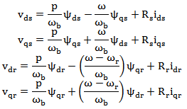 Equations in terms of flux linkages per sec and reactances at base frequency are described as:
 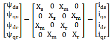 Where Xs, Xm and Xr stand for stator reactance and referred rotor reactance respectively.Torque equations:
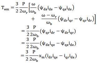
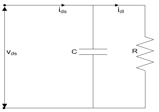 | Figure 1(a). Capacitor d-axis model |
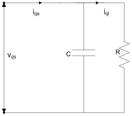 | Figure 1(b). Capacitor q-axis model |
Capacitor side and load side equations are given below:
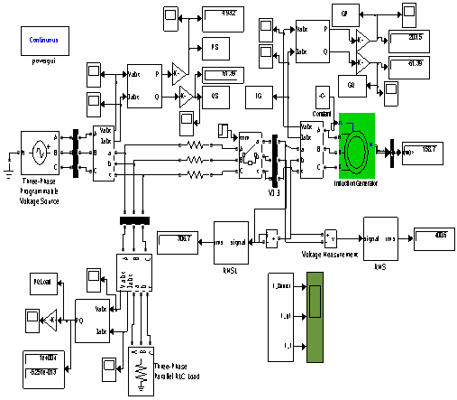 | Figure 2. SIMULINK model of Induction generator operating in grid connected mode |
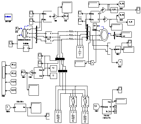 | Figure 3. SIMULINK model of Induction generator operating in self excited mode |
3. Simulated Results
3.1. Grid Connected Operation
As induction generator is connected to a strong grid hence no variations / fluctuations are observed in voltage and frequency. Fig 4 to 17 shows the effect of machine parameters as observed on the power quality issues listed in section 2. The effect of rotor resistance on active power for different values of speed is shown in Fig 4 to Fig 6. Active power output decreases with an increase in rotor resistance and maximum variation is observed for low value of rotor resistances it becomes almost constant for higher value of rotor resistances. Further nature of variations is found to be independent of the ratings of the machines and the operating speeds.From the analysis of Fig 4 to 6 it is recommended to design GCIG with low values of rotor resistance irrespective of the size of the machine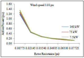 | Figure 4. Effect of Rotor resistance (pu) on Active power (pu), wind speed 1.01pu |
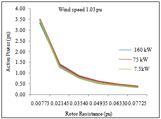 | Figure 5. Effect of Rotor resistance (pu) on Active power (pu), wind speed 1.03pu |
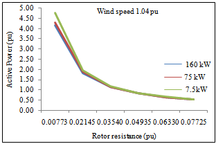 | Figure 6. Effect of Rotor resistance (pu) on Active power (pu), wind speed 1.04pu |
The response of active power with any change in stator inductance at different speeds is shown in Fig 7 to Fig 10.It is observed that with the increase in Ls real power output is found decreasing. Nature of variations is found to be dependent upon the operating speeds and size of the machine.Analysis of Fig 7 to Fig 10 gives the effect of variations in stator inductance on active power as;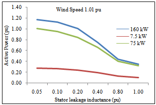 | Figure 7. Effect of Stator leakage inductance (pu) on Active power (pu), wind speed 1.01pu |
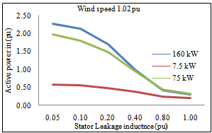 | Figure 8. Effect of Stator leakage inductance (pu) on Active power (pu), wind speed 1.02pu |
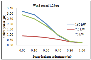 | Figure 9. Effect of Stator leakage inductance (pu) on Active power (pu), wind speed 1.03pu |
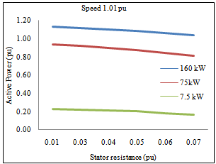
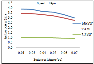
● There is hardly any effect on active power in case of low rating machines. It is significant for large rating machines.● Low value of stator leakage reactance is desirable to deliver maximum power output in case of large machines.The variations in active power at different speeds with change in stator resistance are shown in Fig 11 to Fig 12. Decrease in real power is observed with an increase in the value of Rs (pu) due to additional power loss at any operating speed. Therefore machine is to be designed with low value of stator resistance.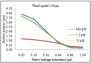 | Figure 10. Effect of Stator leakage inductance (pu) on Active power (pu), wind speed 1.04pu |
 | Figure 11. Effect of Stator resistance (pu) on Active power (pu), wind speed 1.01pu |
 | Figure 12. Effect of Stator resistance (pu) on Active power (pu), wind speed 1.04pu |
Magnetizing reactance “Lm” is found to be the most effective parameter effecting the reactive power consumption of GCIG. The effect of Lm on reactive power is shown in Fig 13 to 16.It is observed that that with increase in Lm there is reduction in reactive power requirement of the machine. This variation is due to the shifting of operating point on the magnetization curve of induction generator due to any change in Lm. Therefore the value of Lm should be high which indicates the low saturation level in the magnetic parts of the machineRotor resistance is found to be effective to control the total harmonic distortion THD (I).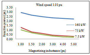 | Figure 13. Effect of Magnetizing Inductance (pu) on reactive power requirement (pu), wind speed of 1.01 pu |
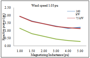 | Figure 15. Effect of Magnetizing Inductance (pu) on reactive power requirement (pu), wind speed of 1.02 pu |
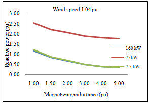 | Figure 16. Effect of Magnetizing Inductance (pu) on reactive power requirement (pu), wind speed of 1.02 pu |
Fig 17 and Fig 18 shows its variation in respective phases with rotor resistance for different operating speeds. From the figures for any operating speed it is observed that● THD (I) increases with increase in rotor resistance for every machine.● Change is more effective in bigger machines in contrast to medium and small rating machines.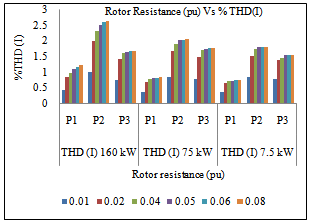 | Figure 17. Effect of Rotor resistance (pu) on %THD (I), wind speed of 1.01 pu |
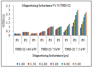 | Figure 18. Effect of Rotor resistance (pu) on %THD (I), wind speed of 1.01 pu |
Therefore in order to reduce THD (I) low value of rotor resistance is found to be desirable for wind energy conversion.
3.2. Self Excited Operation
As the induction generator is operating in SEIG mode the variations in terminal voltage and frequency are observed. Fig 19 to 35 shows simulated results on 160 kW machine to look into the effect of machine parameters on power quality issues. The effect of rotor resistance on active power for two different values of operating speed is shown in Fig 19. Active output power decreases with an increase in rotor resistance and it is observed that the drop is uniform. Therefore in order to deliver more output similar to GCIG here also low values of rotor resistance are desirable. | Figure 19. Effect of rotor resistance (pu) on active power, wind speed of 1.01 pu and 1.04 pu |
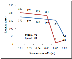
The response of active power with any change in stator resistance, stator inductance and rotor inductance are shown in Fig 20-22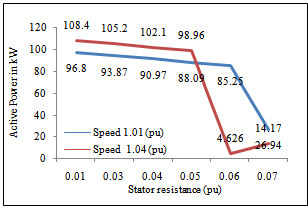 | Figure 20. Effect of stator resistance (pu) on active power, wind speed of 1.01 pu and 1.04 pu |
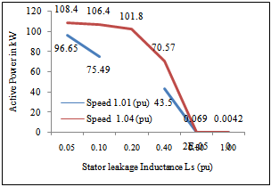 | Figure 21. Effect of stator leakage inductance (pu) on active power, wind speed of 1.01 pu and 1.04 pu |
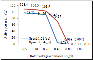 | Figure 22. Effect of rotor leakage inductance (pu) on active power, wind speeds of 1.01 pu and 1.04 pu |
The stator resistance is required to be varied within the limits as increasing the stator resistance beyond certain limits the IG output active power drops sharply. Low values of stator and rotor leakage reactance are desirable to deliver maximum power output. With the increase in speed the active power output of the IG also increases.The variation in reactive power demand of the SEIG with machine parameters is shown in Fig 23 -26. 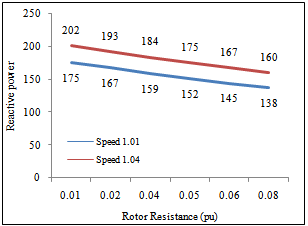 | Figure 23. Effect of rotor resistance (pu) on reactive power requirement, wind speeds of 1.01 pu and 1.04 pu |
 | Figure 24. Effect of stator resistance (pu) on reactive power requirement, wind speed of 1.01 pu and 1.04 pu |
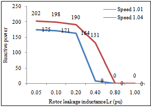 | Figure 26. Effect of rotor inductance (pu) on reactive power, wind speed of 1.01 pu and 1.04 pu |
The reactive power requirement of SEIG is decreases with increase in rotor resistance, stator resistance, stator leakage reactance and rotor leakage reactance. The effects are more predominant than GCIG as in this case there is no grid present to maintain the voltage and to supply reactive power. For a fixed value of excitation capacitor, its reactive power requirement suddenly falls to a lower level due to sudden fall in terminal voltage.Fig 27-30 shows the variation in terminal voltage when machine parameters are varied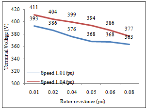 | Figure 27. Effect of rotor resistance (pu) on terminal voltage, wind speed of 1.01 pu and 1.04 pu |
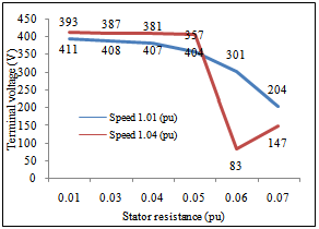 | Figure 28. Effect stator resistance (pu) on terminal voltage with change in at wind speed of 1.01 pu and 1.04 pu |
The terminal voltage of the SEIG drops with the increase in rotor as well as stator resistance. Terminal voltage falls to very low value when stator and rotor leakage reactance are increased beyond certain limits. Therefore terminal voltage seems to be very sensitive in terms of machine parameters. | Figure 29. Effect of stator leakage inductance (pu) on terminal voltage, wind speed 1.01 pu and 1.04 pu |
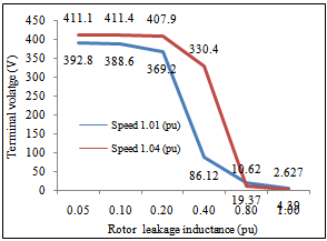 | Figure 30. Effect of rotor leakage inductance (pu) on terminal voltage, wind speed of 1.01 pu and 1.04 pu |
Similarly Fig 31 shows the effect of rotor resistance on generated frequency. It falls with the increase in rotor resistance. All other parameters have not shown any significant effect on the frequency of generated voltage.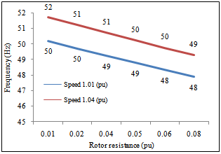 | Figure 31. Effect rotor resistance (pu) on frequency, wind speed of 1.01 pu and 1.04 pu |
All the parameters except magnetizing inductance are found to be effective to control the total harmonics distortion in voltage and current THD (I) & (V).Fig 32 shows total harmonics distortion (current & Voltage) in three phases at operating speed 1.01(pu). It is clear that harmonics distortion is increasing with increase in per unit rotor resistance.Fig 33 shows the effect of variation of stator resistance on THD (I) & THD (V). Lower range of stator resistance is preferred to control THD in current and voltage wave forms.The effect of Increase in Ls and Lr on THD (I) & (V) is recorded and shown in fig 34 and fig 35. Low value of these parameters is favourable to reduce THD current & voltage. 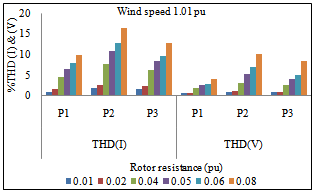 | Figure 32. Effect of rotor resistance (pu) on %THD (I) & (V), wind speed of 1.01 pu |
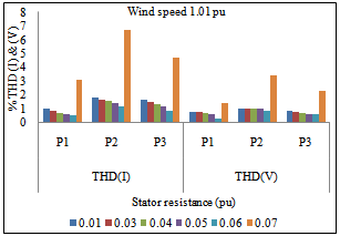 | Figure 33. Effect of stator resistance (pu) on %THD (I) & (V), wind speed of 1.01 pu |
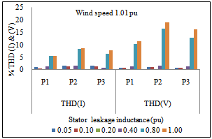 | Figure 34. Effect of stator leakage inductance (pu) on %THD (I) & (V), wind speed of 1.01 pu |
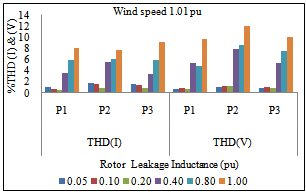 | Figure 35. Effect of rotor leakage inductance (pu) on %THD (I) & (V), wind speed of 1.01 pu |
4. Discussions on Results
Using the simulated results as shown in Fig 4 to fig 35 the following conclusions may be drawn: I) Grid connected induction generators:● For Injecting more active power to the grid machine may be designed with low value of rotor resistance but on the other hand it results into excessive reactive power demand. Therefore one machine may be opted as slip ring induction machine i.e. master controller for active and reactive power control.● Any increase in stator resistance results into a drop in active power output of the machine due to increased power loss in the stator. Low value of stator and rotor leakage reactance is desirable to deliver maximum power output in case of large machines.● Magnetizing reactance “Lm” is found to be the most effective parameter effecting the reactive power consumption of GCIG. Increase in Lm reduces the reactive power requirement of the machine. Therefore the value of Lm should be high which indicates the reduction in magnetizing current for the same value of air gap flux. This may be achieved during the selection of core material for the construction of the machine.● %THD (I) increases with increase in rotor resistance for every machine. Therefore in order to reduce %THD (I) low value of rotor resistance is found to be desirable. II) Self excited induction generators:● Active output power decreases with an increase in rotor resistance & stator resistance. Therefore in order to deliver more output similar to GCIG here also low values of rotor & stator resistance are desirable.● Generated frequency is found to be dependent upon rotor resistance only. It is due to the reduction of speed of rotating air gap flux to meet the additional generation at constant speed operation.● All the machine parameters are found more effective to control the power quality problems in SEIG in contrast to grid connected operation. The reactive power requirement of SEIG decreases with increase in rotor & stator resistance. For a fixed value of excitation capacitor, its reactive power requirement suddenly falls to a lower level due to sudden fall in terminal voltage.● Terminal voltage is found to be very sensitive to all machine parameters. Hence proper design of SEIG can lead to batter voltage regulation.● Rotor parameters are found to be most effective in controlling the %THD, its value Increases with increase in Rr & Lr. Stator resistance effect on %THD is comparatively less.
5. Conclusions
As per discussions in section 4 it may be concluded that the machine parameters affect the power quality when induction generators are operating in grid connected or self excited modes. For better quality supply in terms of active power and THD most of the machine parameters (such as stator and rotor parameters) must be on the lower side for two operations i.e. grid and self excited. Whereas a high value of Lm i.e. magnetizing reactance is recommended for the reduction of magnetizing current or corresponding reactive power import from power network. As far as possible the core construction should be such that the operation is always near to knee point on the saturation curve of the machine i.e. in a low saturation zone. Proposals as made above may be useful to control the power quality issues by proper design of induction generators.
Appendix I:
Induction Generator no 1Nominal power:160kWVoltage (line-to-line):400 VFrequency:50 HzStator resistance (pu):0.01379Rotor resistance (pu):0.007728Stator inductance (pu):0.04775Rotor inductance (pu):0.04775Magnetizing inductance (pu): 2.46Pole pairs:2Induction Generator no 2Nominal power:7.5kWVoltage (line-to-line):400VFrequency:50 HzStator resistance (pu):0.03461Rotor resistance (pu):0.03470Stator inductance (pu):0.04484Rotor inductance (pu):0.04484Magnetizing inductance (pu): 1.89Pole pairs:2Induction Generator no 3Nominal power:75kWVoltage (line-to-line):400 VFrequency:50 HzStator resistance (pu):0.01665Rotor resistance (pu):0.009804Stator inductance (pu):0.04933Rotor inductance (pu):0.04933Magnetizing inductance (pu):1.827Pole pairs:2
References
| [1] | World Wind Energy Association Press Release : June 2011 |
| [2] | Bharat Singh and S.N. Singh “Wind Power Interconnection into the Power System: A Review of Grid Code Requirements” The Electricity Journal, Volume 22, Issue 5, Pages 54-63, June 2009. |
| [3] | Sutanto, D. Grantham, C. Rahman, F. “A regulated self-excited induction generator for use in a remote area power supply” Conference proc. Sixth International Conference on Electrical Machines and Drives, Conf. Publ. No. 376, pp 234 – 239 Year 1993 |
| [4] | Melicio R, Mendes V.M.F, Catalao J.P.S. “Simulation of wind power generation with matrix and multi-level converters: Power quality analysis” 18th International Conference on Electrical Machines (ICEM 2008). pp 1 – 6 Year 2008 |
| [5] | Ching-Yin Lee, Li-Chieh Chen, Shao-Hong Tsai, Wen-Tsan Liu, Yuan-Kang Wu, “The Impact of SCIG Wind Farm Connecting into a Distribution System” Conference proce Power and Energy Engineering Conference (APPEEC 2009) year 2009. |
| [6] | Sudhir Sharma and K.S Sandhu “Induction Generator Parameters Effecting Power Quality: An Exposition” International Journal of Electronics and Electrical Engineering Volume 3, Number 3 pp 247-256, 2010 |
| [7] | Sudhir Sharma, K.S. Sandhu “Power quality issues from wind generation using induction generators - a statistical review” Proceedings of IEEE International Conference on Mechanical and Electrical Technology (ICMET 2010) Singapore, pp – 249-252 September 10-12, 2010 |
| [8] | K.S. Sandhu and Sudhir Sharma “Effects on major power quality issues due to incoming induction generators in power system” ARPN journal of engineering and applied sciences, vol.5 no. 2 pp- 57-65, February 2010 |
| [9] | Sudhir Sharma, K.S. Sandhu “Role of Reactive Power Source on Power Quality of Three-Phase Self-Excited Induction Generator” WSEAS TRANSACTIONS on POWER SYSTEMS, Issue 4, Volume3, pp 216-225, April 2008. |
| [10] | Sudhir Sharma, K.S. Sandhu “Selection of Reactive Power Source for a three-Phase Self-Excited Induction Generator”, International conference MMF’08, Cambridge, Massachusetts, USA, pp 161-165, March 24-26, 2008. |
| [11] | Chicco, G.; Di Leo, P.; Scapino, F.; Spertino, F. “Experimental Analysis of Wind Farms connected to the High Voltage Grid: the Viewpoint of Power Quality” First international Symposium on Environment Identities and Mediterranean Area, 2006. ISEIMA '06, pp184-189, year 2006. |
| [12] | Grunbaum R., “FACTS for Voltage Control and Power Quality Improvement In Distribution Grids," SmartGrids for Distribution, IET-CIRED, CIRED Seminar, pp.1-4, 23-24 June 2008. |
| [13] | Bhim Singh, S. S. Murthy and Sushma Gupta, “Modelling and Analysis of STATCOM Based Voltage Regulator for Self-Excited Induction Generator with Unbalanced Loads”, Conference on Convergent Technologies for Asia-Pacific Region, TENCON 2003, Vol. 3, pp 1109 – 1114, 2003. |
| [14] | Adel M. Sharaf, Khaled Mohamed Abo-Al-Ez, “A Novel FACTS Based (DDSC) Compensator for Power-Quality Enhancement of L.V. Distribution Feeder with a Dispersed Wind Generator”, International Journal of Emerging Electric Power Systems, Vol. 7, Issue 3, pp 1-18, 2006. |
| [15] | Avinash Kishore, R.C. Parsad and B.M. Karan, “ MATLAB SIMULINK based DQ Modelling and Dynamic Characteristics of Three Phase Self Excited Induction Generators”, Symposium on Progress in Electromagnetic Research, Cambridge, USA, pp 312-316, March 26-29, 2006. |
| [16] | Chee-Mun Ong, Dynamic Simulation of Electric Machinery using MATLAB/SIMULINK, Prentice Hall, Inc, 1998 pp 1-615 |
| [17] | Paul C. Krause, Oleg Wasynczuk and Scott D. Sudhoff, Analysis of Electric Machinery and Drive Systems, 2nd Edition, IEEE press,2004, pp 1-605. |
 Abstract
 Reference
 Full-Text PDF
 Full-Text HTML