-
Paper Information
- Next Paper
- Previous Paper
- Paper Submission
-
Journal Information
- About This Journal
- Editorial Board
- Current Issue
- Archive
- Author Guidelines
- Contact Us
International Journal of Energy Engineering
p-ISSN: 2163-1891 e-ISSN: 2163-1905
2012; 2(6): 279-284
doi: 10.5923/j.ijee.20120206.02
Wireless Parameters Monitoring Simulation and Design in Wireless Personal Area Network Using 2.4 GHz Transceiver Module for Wind Mill
 Abstract
 Reference
 Full-Text PDF
 Full-Text HTML
Vivek Kaundal 1, Rajesh Singh 2, Madhu Sharma 1
1University of Petroleum and Energy Studies, Dehradun, India
2HEAD, Robotics Institute R&D, University of Petroleum and Energy Studies, Dehradun, India
Correspondence to: Vivek Kaundal , University of Petroleum and Energy Studies, Dehradun, India.
| Email: |  |
Copyright © 2012 Scientific & Academic Publishing. All Rights Reserved.
A Wireless Personal Area Network (WPAN) monitoring system is proposed to measure the voltage and current generated for wind mill farm, it is considered as a target application. It has a Rigid hub structure, economical larger capacity i.e. 5– 7 MW for offshore sitting and variable speed turbines are three major developments characterize in a wind machines. The forth development is the adoption of gearless wind turbine eliminating gearboxes as weakest link in the chain of modern wind turbines. Eliminating the burdens associated with cabling, the proposed wireless network enables sensors to place on the each individual mill to monitor voltage and current so that we can optimize wind farm productivity. The proposed system consist of ZigBee based wireless personal area network i.e. communication through ZigBee transceiver module, coding of microcontroller through AVR Studio4, and interfacing all with wind mill. The data from the wind-power generator will be collected with the help of proposed system and wired RS-232 Interface. The collected data will be displayed with the help of suitable GUI in MATLAB.
Keywords: WPAN (Wireless Personal Area Network), ZigBee- CC2500, RS-232 interface, MATLAB
Cite this paper: Vivek Kaundal , Rajesh Singh , Madhu Sharma , "Wireless Parameters Monitoring Simulation and Design in Wireless Personal Area Network Using 2.4 GHz Transceiver Module for Wind Mill", International Journal of Energy Engineering, Vol. 2 No. 6, 2012, pp. 279-284. doi: 10.5923/j.ijee.20120206.02.
Article Outline
1. Introduction
- Due to the drawbacks of wired network systems, now a day’s all the wired system is being replaced by wireless systems. In a wired network-• A lot of wiring is required.• Less flexibility.• New devices can’t be accommodated easily.• Costly for networks spread over a large area.In wireless network-• It avoid lot of wiring.• It can add new devices at any time.• Flexibility of physical partitions.• Centralized monitoring can be accessed.To modify the existing design of wind mills engineers must be provided with the information’s like voltage, current, frequency, wind speed and direction, rotor speed, etc. The proper collection of data from the wind power electricity mainly depends on the data collecting and transmission interface and its related system[3].The proposed wireless personal area network system will be designed in the following steps:(1) Remote monitoring and controlling system will be designed as per the requirements of local features.(2) A module for wind-power electricity generator will be designed to transmit real-time parameters during running condition of the wind electricity generator.(2) ZigBee wireless Personal Area Network will be used for the designing a data transmission interface (RS 232) to replace existing design.(3) GUI will be designed to display and store real-time running parameter.
2. Block Diagram
- The proposed transmitting system is shown in Figure1. The main components of this proposed structure areFigure 2 shows the receiving section of the proposed system where Zigbee module received the data wirelessly from Transmitting Zigbee module shown in Figure 2 and the data will be the processed through max 232 IC (To Convert RS logic) and then it will fed to PC through USB to serial cable.(1) Voltage and current module that will read the voltage and current data from the wind mill section and will send it to the microcontroller.(2) Microcontroller reads the input data from the voltage and current module and will process it as per the incoming data and will transfer the final signal to the Zigbee module through USART of microcontroller.
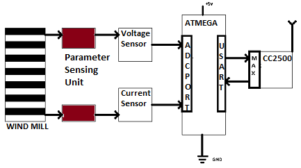 | Figure 1. Block diagram of Measuring section (Transmitting Section) |
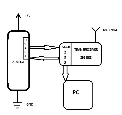 | Figure 2. Block diagram of Data collecting section (Receiving Section) |
3. Hardware Development
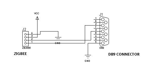
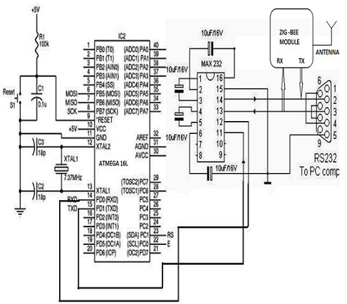
- Figure 3 and Figure 4 shows the interfacing of transmitting section and receiving section .The brief descriptions of components which is used to design a transmitting and receiving end are given below-a) LCD unit- The lcd jhd162A (16x2) is interfaced with AVR microcontroller to display the dta information. The LCD data pins 11,12,13,14 are connected to port C (PC0 through PC3) of the AVR microcontroller. The control pins of LCD 4,5,6 Register-select (RS), Read/write(R/W) and enable are interfaced with PD6, PD5 and PD7 of the AVR microcontroller, respectively. R/W pin is keep permanently low to put the LCD into writing mode.b) Microcontroller-ATMEGA16 is a microcontroller of AVR series. It is low-power; 8-bit CMOS architecture with AVR enhanced reduced instruction set computer (RISC) architecture. ATMEGA 16 has 16 KB of in-system programmable flash memory, 512 bytes on EEPROM, 1 KB of SRAM, two 8-bit timers, one 16-bit timer, 32 general-purpose I/O lines and 32 general-purpose working registers. It integrates all the subsystems to form a complete unit[12].
 | Figure 3. Schematic of Data collection Section (Receiving Section) |
 | Figure 4. Schematic of Measuring section (Transmitting Section) |
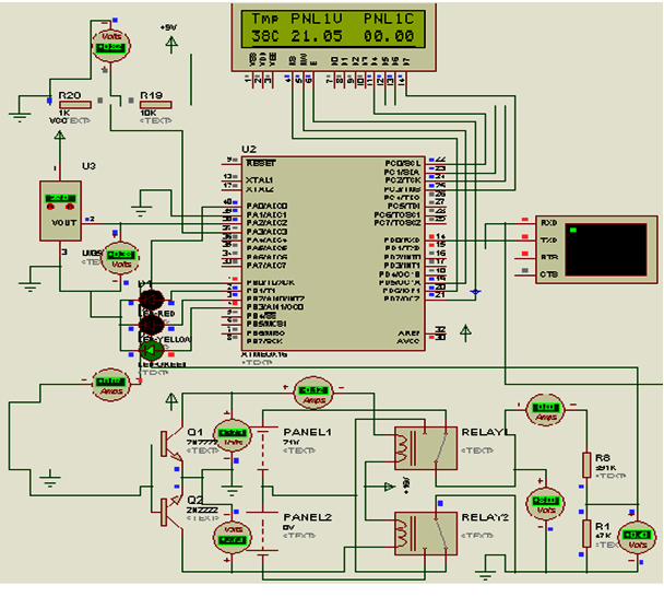 | Figure 5. Simulation model of proposed system using Proteus trial software |
4. Software Development
- The software development of designed system is used to get integration and functionality. ‘C’ language is used to develop the program to drive the system and AVR studio4 is used as compiler (WINAVR is running in backend). AVR studio4 software is free firmware for Windows and Linux operating systems. AVR functions like UART, timer, ADC, interrupts, etc are handled by AVR studio4 and provide the facility to write the program in embedded ‘C’. The resultant of the program is obtained in hex code file which burn into flash memory of AVR microcontroller using a In system USB programmer. The external generated clock of 14.7456MHz is used to activate the microcontroller; the fuse bytes are as follows:low fuse byte = C9high fuse byte = EF
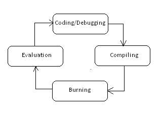 | Figure 6. Steps for software development |
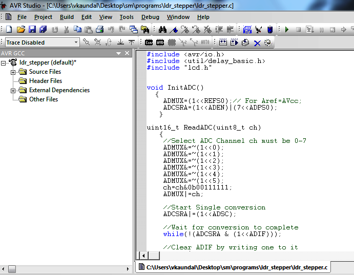 | Figure 7. snapshot C coding for proposed system using of AVRstudio4 |
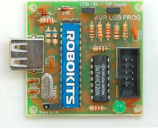 | Figure 8. view of hardware AVR programmer (ISP) by Robokits |
5. Results
- The results of proposed system are shown through the appropriate GUI which is designed using MATLAB. The steps for making any GUI:(1) The first step is to make a Front look for proposed system which is called “GUI” as Graphical User Interface.(2) Settle the properties of each box Like push button, popup menu or box on GUI(3) The GUI is run by pressing run button from editor toolbar or RUN from debug button or simple Function5 (F5).Figure 10 shows the Snapshot of GUI of wireless data capturing using MATLAB.
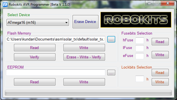 | Figure 9. snapshot of robokits AVR programmer window to erase, write and verify .h file generated by AVRstudio4 to target |
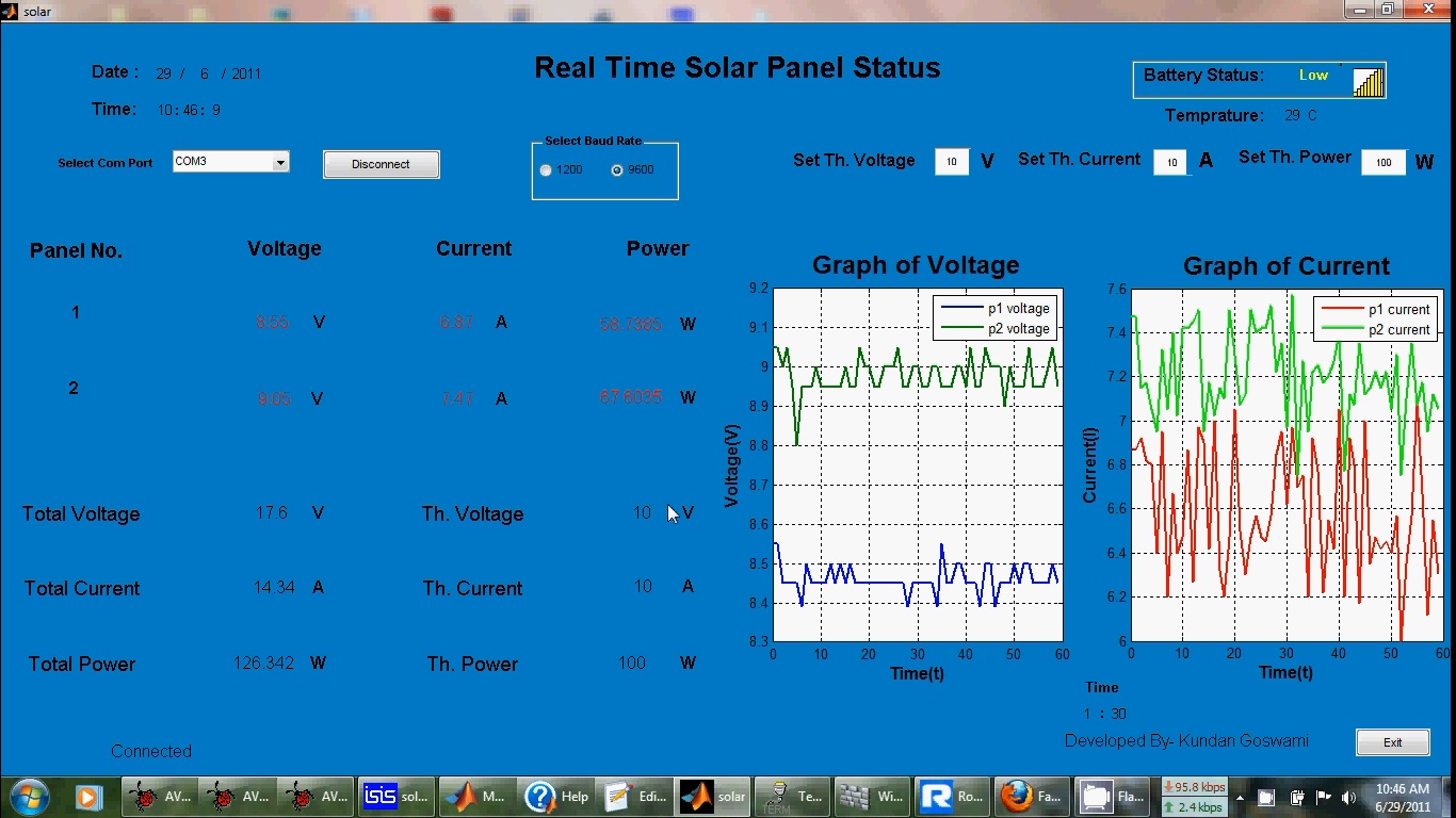 | Figure 10. Snapshot of GUI of wireless data capturing in receiving end using MATLAB |
6. Conclusions and Future Scope
- A low-cost solution to enhance the remote monitoring capability of wind mill system is proposed. Portable model of WPAN system for monitoring voltage and current of wind –electricity generator is designed and developed at lab scale and found that(1)It is secure, robust and low-power consuming.(2)It can operate on multiple channels to avoid interference with other wireless devices (5) Continuous monitoring can help fault detection of particular wind mill in wind farm. The proposed system will provide a method to investigating the behavior of each windmill and will reduce the monitoring cost. Again different sensors for the measurement of parameters like wind speed, temperature, and humidity, will be interfaced for correlation and investigation of the effect of environmental loads. This method can also be applied to energy generation like Solar, Fuel cells, Hydroelectric etc. and they can be monitoring by utilizing heterogeneous wireless personal area networks.
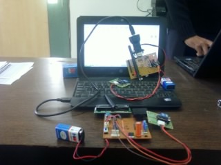 | Figure 11. View of system |
7. View of System
- The view of the demonstration model of the system is shown in the figure 11.