A.N. Anozie 1, P.O. Ayoola 2
1Applied Thermodynamics and Process Design Research Laboratory, Department of Chemical Engineering, Obafemi Awolowo University, Ile-Ife, Nigeria
2African Institute for Science Policy and Innovation, Obafemi Awolowo University, Ile-Ife, Nigeria
Correspondence to: P.O. Ayoola , African Institute for Science Policy and Innovation, Obafemi Awolowo University, Ile-Ife, Nigeria.
| Email: |  |
Copyright © 2012 Scientific & Academic Publishing. All Rights Reserved.
Abstract
This study carried out energy and exergy analyses of a thermal power plant in order to evaluate the energetic and exergetic efficiencies and irreversibilities of units, sections and the overall system. It was also, to determine the optimum fuel-air ratio and optimum combustion temperature at different throughputs. The thermal plant consisting of 23 units and 4 sections was simulated using HYSYS simulation software and EXCEL spreadsheet. The EXCEL spreadsheet was used for the energy and exergy analyses. It was found that throughput did not influence the energy efficiencies of the units but the exergy efficiencies. Throughput did not influence the energy and exergy efficiencies of the sections. The overall energetic efficiencies of the plant were 18.17, 19.79, 21.42, and 21.45% and the overall exergetic efficiencies were 10.26, 11.22, 11.58, and 11.61% for throughputs of 50, 75, 100 and 110%, respectively. The overall irreversibilities of the plant increased as the throughput increased. The optimum fuel-to-air ratio which gave the optimum combustion temperature in the furnace was found to be 1:12.6 for all the throughputs which was an improvement over the current practice of 1:19.8. Throughput did not influence the maximum combustion temperature in the furnace.
Keywords:
Thermal Power Plant, Exergy, Energy, Efficiency, Irreversibility, Units and Sections
1. Introduction
Exergy analysis is a thermodynamic analysis technique based on the first and second laws of thermodynamics which provides an alternative and illuminating means of assessing and comparing processes and systems rationally and meaningfully[7]. Several studies have been carried out by researchers[3, 5, 17] to evaluate the performance of thermal power plants using exergy analysis. Analyses of energy, exergy and exergoeconomics were performed on a natural gas based steam power plant[12]. The comparison of coal-fired and nuclear steam power plants using energy and exergy analyses to identify areas with potential for performance improvement has been investigated[15]. A thermodynamic analysis of a Rankine cycle reheat steam power plant was carried out to study the energy and exergy efficiencies at different operating conditions of boiler temperature, boiler pressure, mass fraction ratio and work output from the cycle[4]. Exergy and cost balances have been used to study gas-turbine cogeneration system[10]. Thermoeconomic analysis of a coal fired electricitygenerating station was performed[16]. The exergetic destructions were investigated on a steam generation system[1]. This study undertakes energy and exergy analysis of a natural gas based thermal power plant, located at Egbin, Ikorodu, Lagos State of Nigeria. The objectives of this study are to determine the energetic and exergetic efficiencies and irreversibilities of the 23 plant units, 4 sections and the overall system and to determine the optimum fuel-air ratio and optimum combustion temperature in the furnace at different throughputs (50, 75, 100 and 110% power output).
2. Plant Description
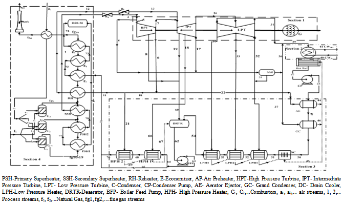 | Figure 1. Process flow diagram of the thermal plant showing the units and sections |
The Egbin thermal power plant burns fossil fuels, which primarily consists of natural gas (NG) and high pour fuel oil (HPFO) as back up, and generates steam which is converted to shaft work in the turbine and to electric power in the generator. The steam generated in the boiler enters the turbine at temperature of about 5400C and pressure of 12.5MPa to spin the turbine blade at a very high speed of 3000 rev/min. There are six turbines units, each capable of generating 220 MW. The water from the lagoon is used as cooling water. The water is passed through the condenser to enhance the condensation of water from steam. The condensed water in the condenser enters the condensate polishing plant for treatment before being sent back to the boiler for re-use. The cooling water which gains temperature from the condenser exits through a discharge channel into the lagoon. The temperature of the effluent water from the powerhouse is reduced in the supplementary cooling system before finally being discharged back into the lagoon[11]. The process flow diagram of the plant is shown in Figure 1.
3. Theory
Two types of exergy of material streams are taken into account, thermo-mechanical (physical) exergy for all streams and chemical exergy associated with the composition of streams with respect to datum environmental species.Physical exergy of streamThe total rate of exergy in a stream is obtained from its specific value as: | (1) |
The specific physical exergy of the stream was evaluated from the following equation: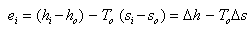 | (2) |
The energy rate of a stream was obtained from its specific value as: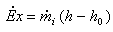 | (3) |
where h and s are the molar enthalpy and entropy, respectively, of the flowing matter, expressed in functional relationship as: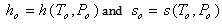 Chemical exergy of streamsFor a mixture of gases, the molar chemical exergy can be expressed as:
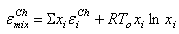 | (4) |
where  is its mole fraction in the mixture and the molar chemical exergies of the individual gases,
  are given in literature[13, 18]. Exergy of chemical reaction: The combustion reaction of methane and oxygen is
 | (5) |
The specific exergy of chemical reaction (kJ/kg) can be written as: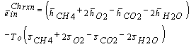 | (6) |
This gives the exergy rate of combustion in the plant as;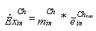 | (7) |
where; is the mass flow rate of chemical substance at the inlet.Energetic and Exergetic efficiencies; and IrreversibilityThe equations used in calculating the energetic and exergetic efficiencies of equipment units are given by:
  | (8) |
 | (9) |
The irreversibility of the unit is given by: | (10) |
The overall energetic  and exergetic
  efficiencies by[6, 9] are:
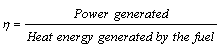
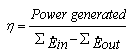 | (11) |
 | (12) |
and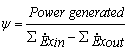 | (13) |
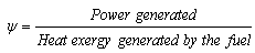 | (14) |
But it must be pointed out that the heat energy or exergy from the combustion reaction must be accounted as an input in the denomination of equations for overall energy and exergy efficiencies given above.The overall irreversibility of the thermal plant is given by:  | (15) |
4. Methodology
SimulationHYSYS (2003) process simulator was used to simulate the plant. The two major equipment in the plant were the turbines and the heat exchangers. The expander was used to simulate the turbine. The Peng-Robinson equation of state was used for the simulation. The thermal plant had 23 units and these were grouped into 4 sections, namely; turbine-generator, condenser, regenerators and boiler-furnace sections as shown in Figure 1. In this analysis, the following assumptions were made: the natural gas burnt in the combustor was assumed to be 87.3% methane, 6.3% ethane, 2.7% propane, 1.5% butane, 0.5% pentane, 0.2% heptanes, 1% CO2, 0.7% nitrogen; the compressed air used in the combustor was standard air; unaccounted heat loss from the system due to radiation and convection was neglected; fuel undergoes complete combustion.Process data were obtained from the plant and thermodynamic properties were obtained from the HYSYS environment once the process was fully converged. Energy and Exergy analysesThe exergy and energy calculations were done using EXCEL spreadsheet after extracting the thermodynamics data from the HYSYS simulations environment. These were calculated using the formulae given in the theory section applied to each unit, section and overall process of the thermal plant.
5. Results and Discussion
5.1. Units Energetic and Exergetic Efficiencies
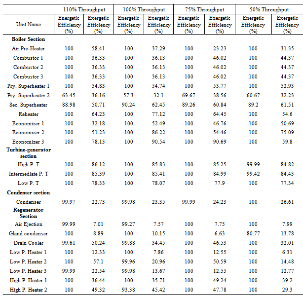
The units energetic and exergetic efficiencies are shown in Table 1. The units energetic efficiencies are mostly 100% because of the assumption of no heat losses that was made in the simulations. The exergetic efficiencies are between 23.23– 90.7% for the furnace-boiler section and between 6.63 – 86.12% for the turbine-generator, condenser and regenerator sections, for all the throughputs. However, as throughput is changed, the operating parameters also change and unit exergetic efficiencies are sensitive to process parameters. The second-law efficiency helped to identify the units that are operating inefficiently. Units with very low exergetic efficiencies are those where the exergy of sink is very low compared to exergy of source such as in the condenser.
5.2. Sections Energetic and Exergetic Efficiencies and Irreversibilities
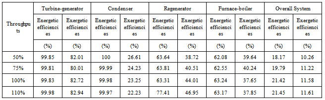
The sections energetic and exergetic efficiencies at different throughputs are shown in Tables 2. The sections energetic efficiencies were between 99.81−99.98% for the turbine-generator section, 99.98−100% for the condenser section, 63.31−77.41% for the regenerator section, and 62.08−63.24% for the furnace-boiler section. The sections exergetic efficiencies were between 80.01−82.94% for the turbine-generator section, 22.23−26.61% for the condenser section, 38.72−46.95% for the regenerators section, and 37.65−40.24% for the furnace-boiler section, for all the throughputs. The reduction in the values of the efficiencies in the sections as compared to the units, was due to the build-up of irreversibilities in the units to the sections. Irreversibilities of the sections showed that the boiler-furnace section of the thermal plant was extremely very high, as shown in Figure 2, compared to other sections within the plant. This was caused by the increase in irreversibilities as heat transfer through a finite temperature difference, chemical reactions, friction, and mixing in the boiler-furnace section of the thermal plant increased.Table 1. The Energetic and Exergetic Efficiencies of Units in the Sections of the Thermal Plant at Different Throughputs
 |
| |
|
Tables 2. The Energetic and Exergetic Efficiencies of Sections and Overall System at Different Throughputs
 |
| |
|
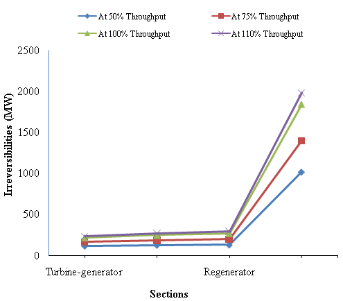 | Figure 2. Variation of the irreversibilities of the sections of the the thermal plant |
| Table 3. Fuel and Air Flow rates and Steam Generated at Different Throughputs |
| | Throughputs (%) | Fuel flow rate(kg/hr) | Air Flow rate(kg/hr) | SteamGenerated(kg/h) | Power outputs (MW) | | 50% | 24,470 | 307,500 | 335,512 | 110 | | 75% | 34,360 | 432,000 | 467,450 | 165 | | 100% | 45,570 | 572,760 | 647,504 | 220 | | 110% | 50,127 | 630,000 | 712,254 | 242 |
|
|
5.3. The Overall System Energetic and Exergetic Efficiencies and Total Irreversibility
Also in Table 2, it can easily be observed that the energetic and exergetic efficiencies of the overall system for all throughputs were very low compared to the units and sections energetic and exergetic efficiencies. The overall energetic efficiencies of the plant were 18.17, 19.79, 21.42, and 21.45% for throughputs of 50, 75, 100 and 110%, respectively. The overall exergetic efficiencies were 10.26, 11.22, 11.58, and 11.61% for throughputs of 50, 75, 100 and 110%, respectively, and showed that overall second-law efficiency of the plant was lower than the energy efficiency as was expected. It was observed that throughput did not significantly improve energy and exergy efficiency of the thermal power plant. As shown in Figure 3, the overall irreversibilities at different throughputs showed that irreversilibities increased as the throughputs increased. The results compared to the coal-based thermal plant showed that the energy and exergy efficiencies were 32% and 28%, respectively. These were higher in values due to differences in methods of calculating the efficiencies[19]. The energy and exergy analyses showed further that thermal plants must be complimented with economic analysis to optimize the operation of the plant.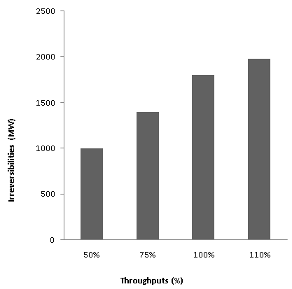 | Figure 3. The overall irreversibilities at different throughputs |
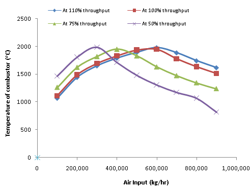 | Figure 4. Variation of combustion temperature with air flowrate at constant fuel to air ratio for different throughputs |
5.4. The Fuel-Air Ratio
The fuel and air flow rates for the throughputs are shown in Table 3. From Table 3, the fuel to air ratio was about 1:12.6 for all the throughputs compared to the present operating ratio of 1:19.8. Excess air results in incomplete combustion, increased air pollutants emissions and fuel wastage. The total power output generated in the plant was proportional to the total fuel flow rate and the mass flow rate of the steam produced. The variations of combustion temperature in the furnace with air flow rates at constant fuel rates for different throughputs are shown in Figure 4. It was observed in Figure 4 that the maximum combustion temperature was about the same for all the throughputs and this was the reason why the overall energetic and exergetic efficiencies do not vary much with throughputs. The air input into the combustor can be used directly in controlling the combustion temperature rather than the indirect method of using the combustion temperature to control the air flow rate as was done in the plant, which would have reduced the time to reach steady state operation.
6. Conclusions
In this work, energetic and exergetic analyses were performed on Egbin thermal power plant. It was found that the units exergetic efficiencies were sensitive to plant throughputs but the sections and overall energetic and exergetic efficiencies were not sensitive to variations in plant throughput. The reason for this behaviour was attributed to the fact that the maximum combustion temperatures in the furnace were about the same for all the throughputs. The overall exergetic efficiency was lower than the overall energetic efficiency as was expected because of proper accounting of different types of process exergies of material, heat and work in the plant.
ACKNOWLEDGEMENTS
The authors gratefully acknowledge the assistance received from the Management of Egbin Thermal Power Plant, Ikorodu, Lagos, Nigeria.
References
| [1] | Alasfour F. N. and Alajmi H. F., “Exergetic destructions in steam generation system”, Azzour plant. Int. Journal of Exergy, 4 (3), 271- 285, 2000. |
| [2] | Ayoola Phillip O., “Exergy Analysis of Egbin Thermal Plant”, An MSc. Thesis submitted to the Department of Chemical Engineering, Obafemi Awolowo University, Ile-Ife, 2010. |
| [3] | Bejan A., Advanced Engineering Thermodynamics, Wiley New York, 1988. |
| [4] | Dincer I. and Al-Muslim H. “Thermodynamics analysis of reheat cycle steam power plants”, Int. Journal Energy Research, 25, 727-739, 2001. |
| [5] | Ebadi M. J. and Gorji-Bandpy M. “Exergetic Analysis of Gas Turbine Plants”. Int. Journal of Exergy Research, 2(1),31-39, 2005. |
| [6] | Goran W. and Mei G. “On Exergy and Sustainable Development-Part 1: Conditions and Concepts”, Exergy International Journal, 1(3): 128-145, 2001. |
| [7] | HYSYS, Version 3.2 (Build 5029), Aspen Technology Inc., Licensed to TEAM LND, Calgary, Alberta, Canada, 2003. |
| [8] | Ibrahim D. and Marc R., “Exergy: Energy, Environment, and Sustainable Development” Applied Energy, 64, 427-440, 2007. |
| [9] | Kotas T.J. “The Exergy Method of Thermal, Plant Analysis”, Krieger, Melbourne, FL, 1995. |
| [10] | Kwon Y., Kwan H. and Oh S., “Exergoeconomic Analysis of Gas Turbine Cogeneration System”. Exergy an International Journal, 1: 31-40, 2001. |
| [11] | Lagos Thermal Station (LTS), “Egbin Operational manual” vol. 2, Hitachi, Ltd., Hitachi works, Tokyo, Japan, 1985. |
| [12] | Mohammad A., Pouria A. and Armita, H. “Energy, Exergy and Exergoeconomic Analysis of a Steam Power Plant”, Int. Journal Energy Research, 33(5), 499-512, 2008. |
| [13] | Moran, M. J. Engineering Thermodynamics, Mechanical Engineering Handbook, Boca Raton CRC, Press LLC, 1999. |
| [14] | Perry R. H. and. Green D. W. Perry’s Chemical Engineer’s Handbook, 7th ed. McGraw-Hill, 1997. |
| [15] | Rosen M. A. “Energy and Exergy Based Comparison of Coal Fired and Nuclear Steam Power Plants”, Exergy an Int. Journal, 1(3), 125-127, 2001. |
| [16] | Rosen M. A. and Dincer, I. “Exergy-Cost-Energy-Mass Analysis of Thermal Systems and Processes”, Energy Convers. Management, 44(10), 1633–1651, 2003. |
| [17] | Sengupta S. Datta, A. and Duttagupta, S. “Exergy Analysis of a Coal-Based 210mw Thermal Power Plant”, Int. Journal Energy Research, 31(1), 14-28, 2007. |
| [18] | Smith J. M. and Van Ness, H. C. Introduction to Chemical Engineering Thermodynamics, McGraw-Hill, 2004. |
| [19] | Suresh M. V., Reddy, K. S. and Kolar, A. K, “Energy and Exergy Based Thermodynamic Analysis of a 62.5MWe Coal-Based Thermal Power Plant”, Int. conference on energy and Environment, August 28-30, Malaysia, 2006. |
 Abstract
 Reference
 Full-Text PDF
 Full-Text HTML