R. Jeevajyothi , D. Devaraj
EEE Department , Kalasalingam University, Virudhunagar, 626126, India
Correspondence to: R. Jeevajyothi , EEE Department , Kalasalingam University, Virudhunagar, 626126, India.
| Email: |  |
Copyright © 2012 Scientific & Academic Publishing. All Rights Reserved.
Abstract
This paper investigates about the enhancement in grid voltage stability while integrating the large-scale variable speed wind turbine (VSWT) with direct drive synchronous generators (DDSG). A dynamic modeling and simulation of a grid connected VSWT driven DDSG with controllable power inverter strategies suitable for the study was developed, tested and verified. This dynamic model with its control scheme can regulate real power, maintain reactive power and generate voltage at different wind speeds. For this paper, studies were conducted on a standard IEEE 14 bus system augmented by a radially connected wind power plant (WPP) which contains 100 wind turbine generators (WTG). The studies include examining the voltage stability (λ-V) curves, voltage magnitude, reactive power delivered, loading margin and voltage collapse of the system. These voltage stability studies are done for the normal state as well as for line contingencies. It is found that large scale VSWT with DDSG at the transmission level has the potential to improve the long-term voltage stability of the grid by injecting reactive power with the help of controllable power inverter strategy.
Keywords:
VSWT, DDSG, Voltage Stability, Grid Connected
1. Introduction
Wind power is the most quickly growing electricity generation source with a 20% annual growth rate for the past five years. Variable speed operation yields 20 to 30 percent more energy than the fixed speed operation, reduces power fluctuations and improves reactive power supply[1]. As wind energy is increasingly integrated into power systems, the stability of existing power systems is becoming a major concern for the power system planners and operators. A natural next step is now to utilize control of the active and reactive power of modern wind turbines to further enhance grid and wind energy installation interaction. The power electronic interface isolates the generator characteristics from the rest of the power system. Only the controlled converter characteristic is seen by the grid[2].There are many papers dedicated to dynamic model development of variable speed wind turbine with DDSG[3,4]. Due to the continuous growth in the demand for electricity with unmatched generation and transmission capacity expansion, voltage instability is emerging as a new challenge to power system planning and operation. .Contingencies such as unexpected line outages in stressed system may often result in voltage instability which may lead to voltage collapse. After a voltage collapse, the system becomes dismantled owing to the wide spread operation of protective devices.Unavailability of sufficient reactive power sources to maintain normal voltage profiles at heavily loaded buses are the prime reasons for the voltage collapse. Research efforts have been made in understanding the phenomenon associated with the voltage instability and suggesting the remedial measures to protect the power system networks against such failures[5].The voltage stability is the ability of a power system to maintain steady acceptable voltages at all buses in the system under normal operating conditions and after being subjected to a disturbance. Power system is voltage stable if voltages after a disturbance are close to voltages at normal operating condition. Voltage stability is also called load stability. The factors contributing to voltage stability are the generator reactive power limits, load characteristics, the characteristics of the reactive power compensation devices and the action of voltage control devices.The objective of this paper is to investigate the grid reinforcing possibilities (voltage stability improvements)[6] that could be achieved by variable speed wind turbine systems with power electronic converters. The wind turbine systems has been tested on IEEE 14-bus test system.Taking a IEEE five-machine, 14-bus system , we attach the WPP system radially through a transmission system and transformers at bus 1 in Figure 2.The equivalent WPP has a set of wind turbines connected in daisy-chain fashion. The DDSG is operated at variable speed with capability to control the voltage at the regulated bus at constant power factor. The impact of wind-generation technology on power system voltage stability is also shown in[7].
2. Modeling
Figure1 presents a schematic diagram of the proposed VSWT with DDSG connected to the grid.
2.1. Wind Turbine
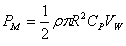
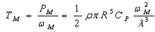
The wind turbine is described by the following equations (1)(2) and (3).  | (1) |
 | (2) |
 | (3) |
where  = tip speed ratioωM=Mechanical speed of wind turbine[rad/s]R= Blade radius[m]VW=wind speed[m/s]PM =Mechanical power from wind turbine[kW]ρ =Air density[kg/m3]CP= Power coefficientTM= Mechanical torque from wind turbine[N · m]The mechanical torque obtained from equation (3) enters as the input torque to the synchronous generator, and is driving the generator. CP may be expressed as a function of the tip speed ratio (TSR)
  given by equation (2).
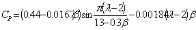 | (4) |
where  is the blade pitch angle. For a fixed pitch type the value of
  is set to a constant value 4.50.
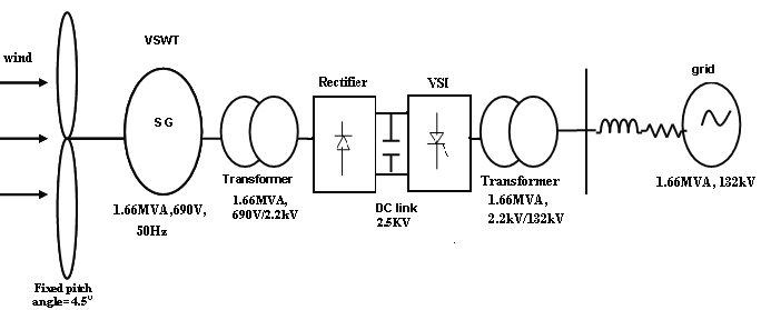 | Figure 1. Schematic diagram of the proposed VSWT with DDSG connected to the grid |
2.2. Synchronous Generator
The DDSG is equipped with an exciter identical to IEEE type 1 model[8 ].The exciter plays a role of helping the dc link to meet the adequate level of inverter output voltage as given in (5) below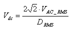 | (5) |
where VAC_RMS is RMS line to neutral voltage of the inverter and DMAX is maximum duty cycle. The exciter plays a role of meeting the dc link voltage requirement.
2.3. Power Electronics Control
This consists of an uncontrolled six-diode rectifier and a six-IGBT voltage source converter (VSC), which is simple, cost-effective and widely used for industrial applications[9]. The VSC includes a LC harmonic filter at its terminal to reduce harmonics it generates. The rectifier converts ac power generated by the wind generator into dc power and power control has to be implemented by the VSC. A current-controlled VSC can transfer the desired real and reactive power by generating an ac current with a desired reference waveform.
3. Analysis of Voltage Stability
3.1. Voltage Instability
A system enters a state of voltage instability when a disturbance, increase in load demand, or change in system condition causes a progressive and uncontrollable drop in voltage. The heart of the problem is usually the voltage drop that occurs when active power and reactive power flow through inductive reactance associated with the transmission network. A power system becomes unstable when voltages uncontrollably decrease due to outage of equipment (line, generator etc.), decrement of production or weakening of voltage control. Voltage instability from the attempt of load dynamics to restore power consumption beyond the capability of the combined and generation system. The main factor causing voltage instability is the inability of the power system to meet the demands for reactive power in the heavily stressed system to keep desired voltages.
3.2. PV Curves for Voltage Stability Analysis
PV curves are used to analyze ‘steady state’ voltage stability which is the stability of the system in normal operation. The ‘nose’ of the PV curve defines the maximum demand that can be served (the ‘Power Limit’) and the associated critical voltage. The upper part of the PV curve is considered to be stable whilst the lower part is considered to be unstable.
3.3. Loading Margin
The loading margin is a measure to estimate power system voltage stability. The loading margin is the difference between operating point of the system and knee (critical loading) point of the system. The voltage collapse points must be assessed in order to guarantee secure operation at the normal operation point.
3.4. Voltage Control Capability
Voltage control refers to the task of keeping the node voltages in the system within the required limits and of preventing any deviation from the nominal value to become larger than allowed.In the DDSG, the reactive power exchange with the grid is not determined by the properties of the generator but by the characteristics of the grid side of the power electronic converter. The generator is fully decoupled from the grid. The power factor of the generator and the power factor of the grid side of the converter can be controlledindependently[10].
3.5. Converter Rating
The converter rating in DDSG based wind turbine is large and thus more expensive. The turbines that are equipped with DDSG can control the terminal voltage. It was concluded that the terminal voltage variation is smoothest in the case of variable-speed wind turbines with voltage control. Furthermore, it was found that only wind turbines with voltage control can compensate a drop in grid voltage.
4. Simulation Results
The modeled controllable power inverter strategy of VSWT with DDSG is connected to IEEE 14-bus test system for voltage stability improvement under normal and contingency states. The VSWT with DDSG is connected at bus-1.Basic data used in the model is given in Table 1. | Table 1. Basic data of DDSG used in the model |
| | Power, voltage and frequency ratings | 600 MVA, 69kV, 50Hz | | Stator resistance Rs | 0.01p.u. | | Direct and Inverse reactances (Xd and Xq) | 1 p.u, 0.8 p.u | | Constant field flux Psi_p | 1 p.u | | Inertia constants Hm | 3KWs/KVA | | Pitch control gain and time constant Kv, Tv | 10p.u, 1 sec | | Active and reactive power control time constants Tep, Teq | 0.01 sec, 0.01 sec | | Number of poles | 4 | | Blade length and number | 75m, 3 | | Pmax and Pmin | 1p.u., 0p.u. | | Qmax. And Qmin | +0.7 p.u, -0.7 p.u | | No. of machines that compose the park | 100 machines of 0.69kV |
|
|
The modeling of the VSWT with DDSG is implemented in MATLAB. The capacity of the VSWT with DDSG is chosen to be 1.66 MVA and real power 1.5 MW. The rated speed of the rotor is chosen to be 40 rpm. The rated wind speed is 15 m/s. the cut-in and cut-out speeds are 4 m/s and 23 m/s respectively. Here, the system is simulated switching frequency of the grid interface inverter is 1.040 kHz. The capacitor value of grid interface rectifier is 2500µF and d.c link voltage is 2.5 kV. The generated voltage of synchronous generator is 0.69KV. The transformer rating of grid connected side is 2kV/130kV. The p.u voltage magnitude of primary of the transformer is 0.99 p.u.. The grid voltage is 130kV. For the variable speed operation of the WECS, a step change in wind speed is used in MATLAB, with a step size of 0.5, a wind speed of 8 m/sec. and 7.5 m/sec. is considered in this system is shown in Figure 2.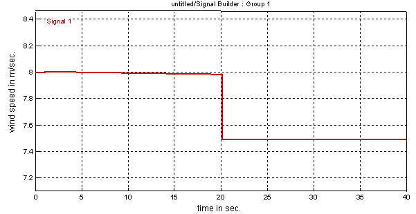 | Figure 2. Wind speed |
Figures (3-9) represents the simulation waveform of the modeled VSWT with DDSG. A glitch occurred in Figures at 20 m/sec. is due to this change in wind speed.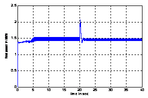 | Figure 3. Simulation waveform of real power of VSWT with DDSG |
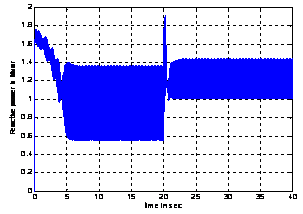 | Figure 4. Simulation waveform of reactive power of VSWT with DDSG |
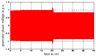 | Figure 5. Simulation waveform of generated phase voltage in pu of VSWT with DDSG |
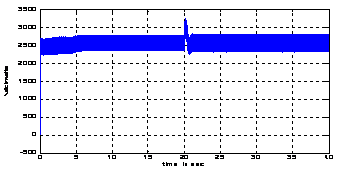 | Figure 6. Simulation waveform of d.c link voltage of VSWT with DDSG |
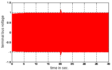 | Figure 7. Phase voltage in pu in grid side of VSWT with DDSG |
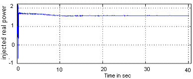 | Figure 8. Simulation waveform of real power in grid side in pu of VSWT with DDSG |
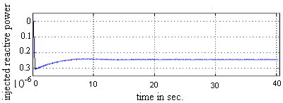 | Figure 9. Simulation waveform of injected reactive power in grid side in pu of VSWT with DDSG |
4.1. Contingencies Considered
To analyse the system under disturbance, several contingencies are considered.• Line 1-5 is removed• Line 4-5 is removed• Line 6-11 is removed
4.2. Improvement in Voltage Magnitude
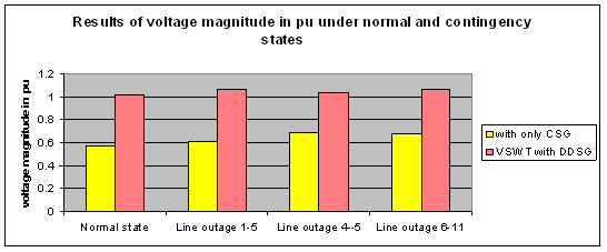
The results of voltage magnitude of bus-6 under normal and contingency states with only conventional synchronous generators (CSG) and when VSWT with DDSG is connected at bus-1is given in Table 2 and the voltage profile of Bus-6 is shown in Figure10.| Table 2. Results of voltage magnitude of bus-6 under normal and contingency states in pu |
| | Voltage magnitude | Normal state | Line outage1-5 | Line utage4-5 | Line outage6-11 | | with only CSG | 0.57076 | 0.61289 | 0.69526 | 0.68063 | | VSWT with DDSG | 1.0165 | 1.07 | 1.0375 | 1.07 |
|
|
 | Figure10. V oltage profile of Bus-6 |
From Figure10, it is observed that VSWT with DDSG has much influence in providing the reactive power compensation. The voltage at bus 6 is within acceptable limits (Vbus5 > 0.95 pu).The reactive power delivered by VSWT with DDSG at bus-1 to bus-6 and bus-5 are given in Table 3 and Table 5 respectively. | Table 3. Reactive power delivered by CSG and VSWT with DDSG at bus-1 to bus-6 |
| | Reactive Power delivered | Normal state | Line outage1-5 | Line outage4-5 | Lineoutage6-11 | | with only CSG | 0.6488 | 0.659 | 0.7751 | 0.75 | | VSWT with DDSG | 1.1571 | 1.15 | 1.1501 | 1.15 |
|
|
`Figure 11. represents the profile of.reactive power delivered to Bus-6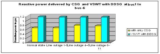 | Figure 11. Profile of .reactive power delivered to Bus-6 |
The results of voltage magnitude of bus-5 under normal and contingency states are given in Table 4 and the voltage profile of Bus-5 is shown in Figure12.| Table 4. Results of voltage magnitude of bus-5 under normal and contingency states in pu |
| | Voltage magnitude | Normal state | Line outage 1-5 | Line outage 4-5 | Line outage 6-11 | | with only CSG | 0.68306 | 0.75155 | 0.76419 | 0.84 | | VSWT with DDSG | 0.81681 | 0.79086 | 0.86163 | 0.85091 |
|
|
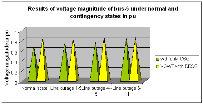 | Figure12. Voltage profile of bus-5 |
| Table 5. Reactive power delivered by CSG and VSWT with DDSG at bus-1 to bus-5 |
| | Reactive power delivered | Normal state | Line outage 1-5 | Line outage 4-5 | Line outage 6-11 | | with only CSG | 0.6488 | 0.659 | 0.7751 | 0.75 | | VSWT with DDSG | 1.1571 | 1.34 | 1.1501 | 1..2 |
|
|
From the contingency analysis, line outages 1-5, 4-5 and 6-11 have found to be the most severe cases. These contingencies cause a large voltage drop at bus 5. Figure13 represents the profile of .reactive power delivered to Bus-5. The voltage at bus 5 is below the acceptable limit (Vbus5 < 0.95 p.u.). This could be observed from Table 4 and Figure 12. The reason for this lower voltage is that bus-5 is far-away from bus-1.Also reactive power cannot travel over a very long distance.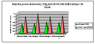 | Figure13. Profile of .reactive power delivered to Bus-5 |
In both the above cases, the influence of VSWT with DDSG is more compared to the system without WTG. The controllable power inverter strategy of DDSG was applied to enhance the voltage stability under normal and contingency states.
4.3. Improvement in Loading Margin
The results of loading margin under normal and contingency states are given in Table 6. Figure14 represents the loading margin curve with only CSG. Figure15 represents shows the loading margin curve when VSWT with DDSG is connected at bus-1 during line 4-5 outage. The profile of loading margin is given in Figure 16.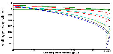 | Figure 14. Loading margin with only CSG |
 | Figure 15. Loading margin when VSWT with DDSG is connected at bus 1 |
| Table 6. Results of loading margin under normal and contingency states in pu |
| | Loading margin | Normal state | Line outage 1-5 | Line outage 4-5 | Line outage6-11 | | with only CSG | 2.53421 | 2.2580 | 2.4880 | 2.1650 | | VSWT with DDSG | 2.8523 | 2.2663 | 2.7379 | 2.4188 |
|
|
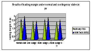 | Figure 16. Profile of loading margin |
With increasing reactive power injection from the wind turbine, the maximum deliverable power to the load increases. So compared to CSG, VSWT with DDSG has much influence in improving the loading margin.
4.4. λ-V Diagram of different types of Wind Turbine Systems
Figure17 represents the Bus6 λ-V diagram with only CSG.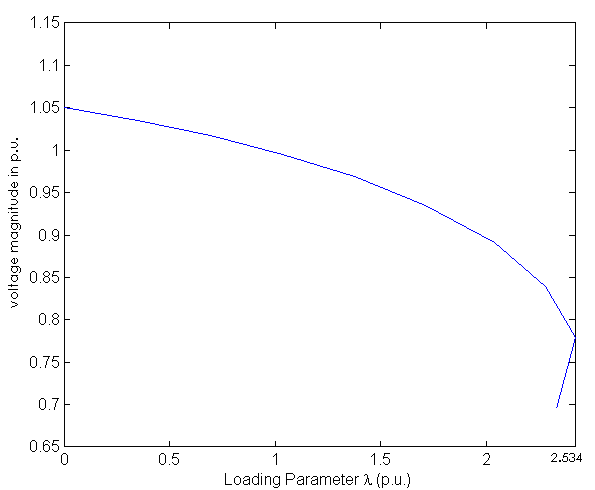 | Figure 17. Bus6 λ-V diagram with only CSG |
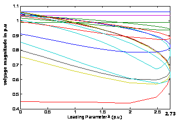
Figure18 represents the Bus6 λ-V diagram when VSWT with DDSG is connected at bus -1.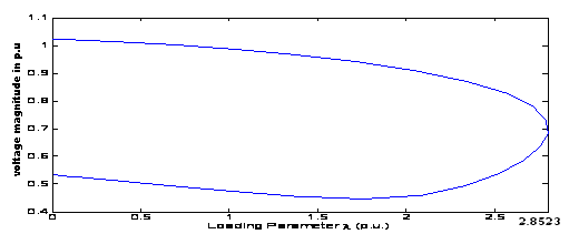 | Figure18. Bus6 λ-V diagram when when a VSWT with DDSG is connected at bus 1 |
It is clear from Figure 18 that the maximum deliverable power (Pmax) is increased by using the reactive power injection facility of the VSWT with DDSG. In other words, the voltage stability margin could be increased by reactive power injection capability of the VSWT with DDSG.
4.5. Voltage Vs Time Curve after the Contingency
The result of high-voltage transmission-line disconnection is given here. The resulting voltage levels in the system are presented in Figures 19 and 20. After the line disconnection, the Bus-12 voltage drops due to the increasing reactive losses in the line, and to the reduced line charging. With only conventional synchronous generators, the transmission level voltage (Bus-12) drops to 0.825pu. The voltage at bus 12 is now below the acceptable limit ( Vbus12 < 0.95 p.u.),and can initiate a voltage collapse event . 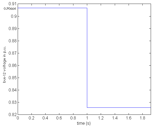 | Figure 19. BUS12 voltage after the disconnection of one of the transmission lines with only CSG |
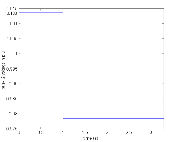 | Figure 20. BUS12 voltage after the disconnection of one of the transmission lines when VSWT with DDSG is connected at bus 1 |
However, when VSWT with DDSG is connected, a possible voltage collapse event is avoided( Vbus12 > 0.95 p.u.). Injecting reactive power into the load bus is a well known method to improve the steady state power transmitted by the existing transmission line and also to improve the voltage stability limit[7]. In this case, the VSWT system utilizes its reactive-power injection capability to maintain voltage on the transmission level (BUS12) within the allowed limit( ±5% deviation) after the grid disturbance. Most of the load-side voltage (BUS12) is restored by this wind farm action. The above calculations show a grid stabilizing property of VSWT with DDSG. It is clear from the results that, the power electronic converter of the VSWT with DDSG can be utilized to increase the voltage stability limit of the nearby load bus.
5. Conclusions
A dynamic model of a VSWT with DDSG and power electronic interface is implemented in MATLAB. The VSWT component models and control scheme are built by using user-defined and built-in components provided in the software. Contingency tests are carried out to study the voltage stability (λ-V )curves, voltage magnitude, reactive power delivered ,loading margin and voltage collapse of the system connected with VSWT under variable wind speed conditions. It was found that VSWT with DDSG could assist the grid to delay or prevent a voltage collapse event. The improvement of voltage stability of a system when connected with VSWT and DDSG is large compared to the system with only conventional generators.Further, it is found that the farms grid integrated on the distribution level and mixed with other loads may possibly increase the long-term voltage stability limit of the system when the control was modified. In the cases demonstrated in this paper, an instability is completely avoided. In addition, with the modified control, voltage dips could be mitigated by VSWT with DDSG.
References
| [1] | U.S. Department of Energy, “20% Wind Energy by 2030 – Increasing Wind Energy’s Contribution to U.S. Electricity Supply”,DOE/GO-102008-2567,2008. http://www1.eere.energy.gov/windandhydro/pdfs/41869.pdf |
| [2] | T. Gjengedal, “Integration of wind power and the impact on power system operation,” in Proc. 2003 Large Eng. Syst . Conf. Power Eng., 2003, pp. 76–83. |
| [3] | Slootweg.H. “Wind Power: Modeling and Impact on Power System Dynamics”,Ph.D. Thesis, Technical University Delft, Netherlands, 2003. |
| [4] | Margaris, I. D. and Hatziargyriou N. D., “Direct drive synchronous generator wind turbine models for power system studies”, Power Generation, Transmission, Distribution and Energy Conversion (MedPower 2010), 7th Mediterranean Conference and Exhibition ,2011. |
| [5] | D. Devaraj , J. Preetha Roselyn,”Genetic algorithm based reactive power dispatch for voltage stability improvement,” Electrical Power and Energy Systems,2010. |
| [6] | Nayeem Rahmat Ullah, and Torbjorn Thiringer, Member, IEEE, “Variable Speed Wind Turbines for Power System Stability Enhancement” IEEE Transactions on energy conversion, vol. 22, no. 1,March 2007. |
| [7] | Muljadi E., et. al., “Impact of Wind Power Plants on Voltage and Transient Stability of Power Systems”, IEEE Energy 2030 ,Atlanta, Georgia,USA,pp.17-18, 2008. |
| [8] | Tande J.O.G., et. al.,“Dynamic models of wind farms for power system studies– status by IEA Wind R&D Annex21”, European Wind Energy Conference & Exhibition, London, U.K November ,pp.22−25,2004. |
| [9] | Seul-Kki Kim and Eung-Sang Kim, “ PSCAD/EMTDC based modeling and analysis of a gearless variable speed wnd turbine”,IEEE Trans. Energy Convers. Vol.22, No.2, pp.421-430, 2007 . |
| [10] | V. Custem and C. Vournas, , “Voltage Stability of Electric Power Systems’,Boston, MA: Kluwer, 1998. |
 Abstract
 Reference
 Full-Text PDF
 Full-Text HTML