Pradeep Patanwar , S.K. Shukla
Department of Mechanical Engineering, Institute of Technology Banaras Hindu University, Varanasi , 221005, India
Correspondence to: S.K. Shukla , Department of Mechanical Engineering, Institute of Technology Banaras Hindu University, Varanasi , 221005, India.
| Email: |  |
Copyright © 2012 Scientific & Academic Publishing. All Rights Reserved.
Abstract
With the drastically change in climatic conditions in recent years, demand for air conditioning is spreading all over the world. This causes a primary consumption of energy in high quantity. In order to provide the best indoor air quality and thermal comfort with minimum consumption of energy, the hybrid desiccant cooling system is one of the options in our daily life. In this paper, an experimental performance study has been done on the hybrid desiccant cooling system. The effects of various parameters on performance of the system have also been observed. It is found that the influence of the parameters studied on the dehumidification rate is similar to those reported earlier.
Keywords:
Hybrid Desiccant Cooling System, Calcium Chloride, Random Packing, Polypropylene Cascade Ring
Nomenclature
P = Pressure (bar)T = Temperature (K)t = Temperature ( ͦ C )ε = Effectivenessρ = Density ( )ξ = Concentration (%)ɸ = Relative Humidity (%)W = Specific Humidity (
 )m = moisture removal rate
  G = mass flow rate
  L = Latent Heat of Condensation
  Subscripta = Airs = Solutioni = Inleto = OutletCaCl2 = Calcium ChlorideHE = Heat Exchangerc = cooling medium
1. Introduction
The liquid desiccant air-conditioning system utilizes low grade heat energy and is environmentally friendly. The dehumidifier and regenerator are the key components of the hybrid desiccant cooling system. The hybrid cooling system consists of a vapour compression system, efficient in sensible cooling, and desiccant dehumidifiers, efficient in removing latent heat load. On combining the two systems we get a hybrid system. This concept has been proposed by several investigators including Meckler[13] and Schlepp and Schultz[12]. Meckler [13] has designed and installed several air conditioning systems that integrate solid or liquid desiccant dehumidifiers with conventional vapour compression systems for air conditioning of commercial and institutional buildings. Integration of commercially available dehumidifiers for latent heat removal and conventional vapour compression systems for sensible heat removal for supermarket applications is economical today. Alizadeh et al.[11] designed, optimized and constructed a prototype of a forced flow solar collector/Regenerator. They employed an aqueous solution of calcium chloride as desiccant and studied the influence of parameters, such as air and desiccant solution flow rates as well as the climatic conditions on the regenerator’s performance. The performance of a regenerator was measured by the rate at which it removed water vapour from the weak desiccant solution. The conclusion reached in that study was that the performance of the regenerator increased as the air flow-rate increased. The solar collector efficiency generally increased with the increase of the air mass flow-rate. The existence of an optimum value of the air flow-rate at which the efficiency is maximal was also predicted. A strong influence of the solar insolation on the collector/regenerator thermal performance was noticed. Yadav[2] simulated a hybrid desiccant cooling system comprising the traditional vapour compression air conditioning system coupled with a liquid desiccant dehumidifier which was regenerated by solar energy. The study suggested that, when the latent load constitutes 90% of the total cooling load, the system can generate up to 80% of energy savings. Dai et al.[4] conducted a comparative study of a standalone VCS, the desiccant-associated VCS, and the desiccant and evaporative cooling associated VCS. The authors found an increase of cold production by 38.8–76% and that of COP by 20–30%. Mazzei et al.[8] compared the operating costs of the desiccant and traditional systems using the computer simulation tool and predicted operating cost savings of about 35% and a reduction of thermal power up to 52%. In the case were the desiccant would be regenerated by waste heat, the authors projected operating costs savings reaching up to 87%. Sanjeev et al.[10] studied theoretically and experimentally a liquid desiccant cooling system made of a falling film tubular absorber and a falling film regenerator. For the purpose of performance evaluation, the authors defined wetness factors to characterise the uniformity of wetting of the surface of the contactors (dehumidifier and regenerator) by the desiccant solution. Their study is of great interest for designing viewpoint, as it can help calculate more accurately the size of the contactors. Kadoma et al.[7] investigated the impact of the desiccant wheel speed, air velocity and regeneration temperature on the COP. The authors showed the existence of an optimal speed and established that the COP decreased when the airflow rate increased and, on the contrary, the temperature of regeneration and the cooling capacity had the same evolution tendency.Various authors have done parametric study and optimized the performance of the hybrid desiccant cooling systems. Giovanni Angrisani and Francesco Minichiello[14] optimized a desiccant HVAC system coupled to a small size co-generator where they concluded that the performances of the two systems are strongly influenced by outdoor thermal-hygrometric conditions and guaranteed a primary energy saving when outdoor air humidity ratio is lower than a certain value (11.5 g/kg) and outdoor air temperature is in the range 25 – 36℃. Later in 2011, Avadhesh Yadav and V.K.Bajpai[15] founded that the 10RPH and 20RPH are the optimum parameter of desiccant wheel for the rotation speed. This study was carried out to evaluate the dehumidification rate of air in a dehumidifier packed tower structure using the liquid desiccant H2O/CaCl2 and by varying the liquid desiccant, airflow rates, inlet air and desiccant conditions. In the present study, the performance as well as parametric study for a hybrid desiccant cooling system has been done. The experiments were performed at Renewable Energy Lab of Mechanical Engineering Department, Institute of Technology, Banaras Hindu University, Varanasi, India.
2. System Description
The Hybrid desiccant cooling system basically consists of two packed towers (Figure1). One is for absorption and another one is for regeneration. Both towers are in cylindrical in shape and of similar size. The towers are made of up of fibre reinforced plastic (FRP) of thickness 4 mm and it has a constant height of 100cm .Packing is done using polypropylene cascade ring of specific surface area 205  for a height of 30 cm .Beneath both the towers, a collection tank made up of aluminium, for storage of the liquid desiccant has been provided. The arrangement for the tanks is such that heated desiccant is sprayed on to the regenerator and cool desiccant is sprayed on to the absorber.
 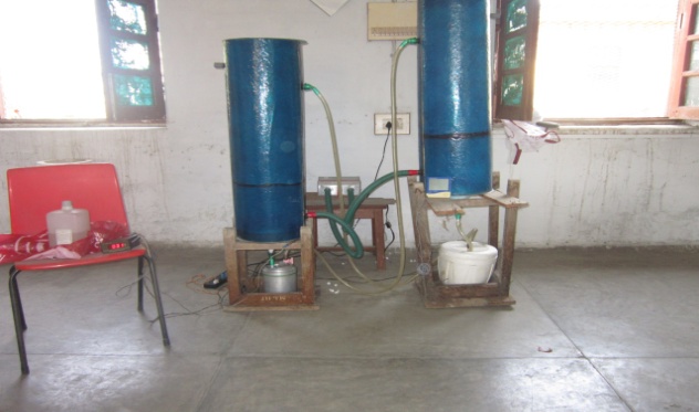 | Figure 1. Photograph of Experiment Setup |
In the absorber, moisture is absorbed from the incoming air stream, due to the vapour pressure difference between the air and solution. Thereby, the dehumidification takes place. From the absorber, the desiccant falls into a collection tank where it is heated to an elevated temperature so as to increase its vapour pressure and this heated desiccant is sprayed on to the regenerator where the moisture is transferred into the air stream. A PT100 sensor is used to sense the temperature of the heated desiccant. The other tank is cooled using an ice which is covered with thermocoal to avoid any heat exchange with surrounding. In the towers, the desiccant and air flow in a counter current manner. Desiccant is sprayed on to the packing and air moves upward through the packing. For obtaining the airflow, two centrifugal fans of capacity of 10 m3 /min each, are installed at the entry of the two towers. Two centrifugal pumps each with a maximum discharge of 800 litre /hour are used for pumping the desiccant into the two towers. Desiccant is distributed into the towers by means of multi point distributor made of PVC pipes and it trickles down through the packing to the outlet, which is situated at the bottom. Demister pads are placed at the top of the two towers to eliminate desiccant carry over through the air stream. The specifications of the measuring devices used are given in Table 1.| Table 1. System Specifications |
| | Quantity | Manufacturer | | Air Flow Anemometer | 0 to 30 m/s | | Desiccant Charge | 35% CaCl2 | | Desiccant Flow | 0.125 L/s | | Thermocouple | -250ºC to 300ºC | | Hygrometer | 0 to 100 % RH |
|
|
Once steady state conditions have been attained, the different measurements viz inlet and outlet temperature of the desiccant and air , using calibrated T type thermocouples, inlet and outlet air relative humidity using digital capacitive probe hygrometer inlet and outlet desiccant concentration, are measured. In the measurement of concentration of desiccant, weight of a known quantity (100ml) of the desiccant is taken whereby its density is calculated and the concentration is calculated using the correlation developed by Manuel R. Conde[1]. Once these readings are obtained for the dehumidifier, the moisture removal rate is calculated and the effect of the different variables namely air inlet temperature, desiccant inlet temperature solution to air flow ratio is studied. For studying their effect, one variable is changed keeping all others at their mean values and their effects are studied for both absorber and regenerator.
3. Mathematical Modelling
The performance of desiccant cooling system can be evaluated using the hereafter mathematical expressions. These expressions were derived by the author Gandhidasan P et al.,[5]. The air moisture removal effectiveness is defined by | (1) |
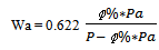
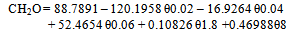
where Pa,i, Pa,o, Ps,i, designate respectively the air inlet water vapour pressure, air outlet water vapour pressure, and the solution vapour pressure.The vapour pressure of inside as well as outside air is obtained by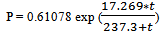 | (2) |
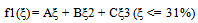
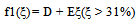
The vapour pressure of CaCl2 is calculated by | (3) |
 | (4) |
 | (5) |
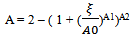 | (6) |
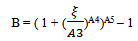 | (7) |
 | (8) |
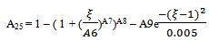
f (water) is the vapour pressure above the normal water surface at different temperature.Table 2 show the values of parameters used in the vapour pressure calculations below. Vapour pressure on the water surface is calculated by-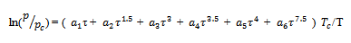 | (9) |
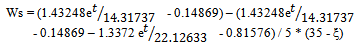
where p is the pressure, T = T90, and subscript c indicates the values at the critical point; τ = 1 – T/Tc. The values for substitution in the equation are: = 647.096 K, = 220.64 kPa, = -7.85951783, = 1.84408259, = -11.7866497, = 22.6807411, = -15.9618719, = 1.80122502Likewise, the desiccant cooling efficiency is defined by | (10) |
where Ts,o, Ts,i, Tc,i, designate, respectively, the desiccant solution outlet temperature, the desiccant solution inlet temperature, the cooling medium inlet temperature.The outlet temperature of the desiccant solution is derived from the above expression and represented by the expression | (11) |
The relation linking the concentrations of inlet and outlet desiccant solution is given by | (12) |
Finally the mass rate of moisture removal is obtained from above equation.From the previous studies on the traditional packed bed dehumidifiers, the values of Ga/Gs were slightly more. (Factor and Grossman, 1980, Ga/Gs ¼ 1.25–2; Fumo and Goswami, 2002, Ga/Gs ¼ 1.3–3.3; Saman and Alizadeh, 2002, Ga/Gs ¼ 3.2–9.4.). But in our case, we have taken the Ga/Gs as lower than 1. This is because to achieve the required cooling air parameters.The moisture absorption capacity per litre solution per second is defined as the dehumidification capability of this sort of solution or the moisture removal rate by air is given by the following equation: | (13) |
 | (14) |
 | (15) |
 | (16) |
Now, if an heat exchanger is used between the absorber and regenerator, then the moisture removal rate is given by following equation: | (17) |
The Heat Capacity of Air, Ca is calculated by- | (18) |
The Heat Capacity of CaCl2 is calculated as per Table 3 and given by-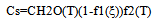 | (19) |
 | (20) |
 | (21) |
 | (22) |
 | (23) |
 | (24) |
| Table 2. Parameters of the vapour pressure equation for solution |
| |
| 0.31 | 3.698 | 0.6 | 0.231 | 4.584 | 0.49 | 0.478 | -5.2 | -0.4 | 0.018 |
|
|
| Table 3. Parameters of the specific thermal capacity equation for solutions |
| | A | B | C | D | E | F | G | H | | 1.63799 | -1.6900 | 1.05124 | 0.0 | 0.0 | 58.5225 | -105.63 | 47.794 |
|
|
4. Result and Discussion
The equations 2-9 have been used to calculate the performance data varying the air temperature from 30.1ºC to 33.1ºC. Figure 2 shows the variation of moisture removal effectiveness with the inlet air temperature. It is clear from the figure that by increasing inlet air temperature, the moisture removal effectiveness of air also goes on increasing. Here, when air temperature is lower than desiccant solution temperature, then air is heated up by desiccant solution and sensible heat is transferred from air to desiccant solution. But on increasing air temperature, air temperature dominates over desiccant temperature and able to transfer both sensible heat as well as latent heat.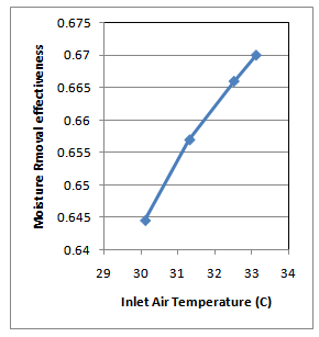 | Figure 2. Moisture Removal Rate v/s Inlet Air Temperature |
Under the constant desiccant flow rate and desiccant inlet concentration, the outlet desiccant concentration is calculated and thereby moisture removal rate (m ͦ) by using equation 12. In the measurement of concentration of desiccant, weight of a known quantity (100ml) of the desiccant is taken whereby its density is calculated along with its temperature and the concentration is calculated using the correlation developed by Manuel R. Conde[1].Figure 3 shows the variation of moisture removal rate with outlet desiccant concentration. It reveals that varying outlet concentration from 4.37 to 5.2 gives rise to moisture removal rate. This shows that by increasing outlet concentration, the absorption capacity of desiccant goes on decreasing and thus moisture removal rate also goes on decreasing.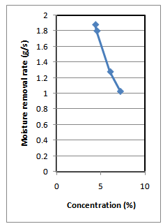 | Figure 3. Moisture Removal Rate v/s Desiccant Outlet Concentration |
In Figure 4, as shown below, the variation of moisture removal rate with humidity change under the same air temperature has been depicted. This shows that by increasing humidity change, moisture removal rate also goes on increasing. It means that when increasing moisture inside air, latent heat also increases due to more condensation of moisture. This extra amount of latent heat increases the temperature of air and thus it increases the moisture removal rate.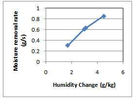 | Figure 4. Moisture Removal Rate v/s Humidity Change |
Figure 5 shown below, depicts the variation of air flow rate with the moisture removal rate. It is observed by the figure that by increasing air flow rate, moisture removal rate also goes on increasing under the constant desiccant flow rate. It is due to the fact that by increasing air flow rate, more amount of moisture comes in contact with desiccant. This led to greater amount of condensation of moisture in a solution which overall increases moisture removal rate.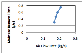 | Figure 5. Moisture Removal Rate v/s Air Flow Rate |
4.1. Parametric Studies
The following input parameters have been used to study the effect of various parameters on the performance of the system.Inlet Desiccant Temperature = 17 ͦC, Inlet Air Humidity = 14  , Desiccant flow rate = 0.2685
  , Desiccant concentration = 35 %
4.1.1. Effect of Inlet Air Temperature
Figure 6 shows the variation of moisture removal rate with inlet air temperature. It is clear from the figure that if the air temperature is less than the desiccant temperature, the air exchanges only sensible heat but when air temperature becomes more than desiccant temperatures, then latent heat also add significantly and thus there is a sudden increment in curve.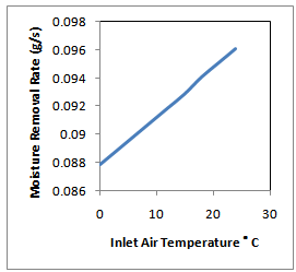 | Figure 6. Moisture Removal Rate v/s Inlet Air Temperature |
4.1.2. Effect of Desiccant Outlet Concentration
Figure 7 shows the variation of moisture removal rate with outlet desiccant concentration. Now, on varying outlet concentration from 0.10 to 0.45, moisture removal rate goes on decreasing. This means that on increasing outlet concentration, the absorption capacity of desiccant goes on decreasing and thus moisture removal rate also goes on decreasing.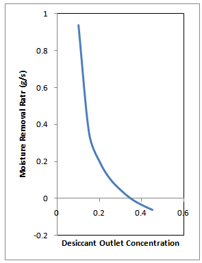 | Figure 7. Moisture Removal Rate v/s Desiccant Outlet Concentration |
4.1.3. Effect of Outlet Air Temperature
Figure 8 shows the variation of moisture removal effectiveness with the outlet air temperature. The reason behind it is that on increasing the air temperature, the air goes on losing its capability to exchange its sensible heat due to closeness of temperature difference.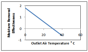 | Figure 8. Moisture Removal Effectiveness v/s Outlet Air Temperature |
4.1.4. Effect of Air Flow Rate
Figure 9 shows the variation of moisture removal rate with humid air flow rate. Here, on increasing air flow rate, moisture removal rate also goes on increasing under the constant desiccant flow rate. On increasing air flow rate, more amount of moisture comes in contact with desiccant. This led to greater amount of condensation of moisture in a solution which overall increases moisture removal rate.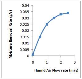 | Figure 9. Moisture Removal Rate v/s Air Flow Rate |
5. Conclusions
The following are the conclusions drawn from the present study:•Increased inlet air temperature helps the desiccant solution to easily trap the moisture from humid fresh air and thus increases the effectiveness.•Increased air flow rate enhances the condensation of moisture and thus overall increases moisture removal rate.•Similarly, increased humidity also enhances condensation and thereby moisture removal rate.•The optimum inlet temperature should be more than 17℃ when the desiccant inlet temperature is 17℃ and desiccant concentration is 35 %.•The optimum desiccant outlet concentration should be between 0.2 to 0.9. This range has been found to be the most effective for moisture removal if the inlet desiccant concentration is 35 % and desiccant flow rate to be 0.2685 kg/s.•The optimum air flow rate should be between 1.5 m/s to 2.5 m/s if the desiccant flow rate assumed to be 0.2685 kg/s and inlet humidity ratio to be 14 g/kg.The influence of the parameters studied on the dehumidification rate can be assumed to be linear. Further research work with other desiccant solutions and different cascade ring for efficient mixing of air and desiccant solution can be undertaken to analyse the system performance.
References
| [1] | Conde, M.R., Properties of aqueous solutions of lithium and calcium chlorides: formulations for use in air conditioning equipment design. International Journal of Thermal Science 43, 367–382, 2004. |
| [2] | Yadav YK,. Vapour-compression and liquid-desiccant hybrid solar space-conditioning system for energy conservation. Renewable Energy 7, 719–23, (1995). |
| [3] | Dai YJ, Wang RZ, Zhang HF, Yu JD, Use of desiccant cooling to improve the performance of vapour compression air conditioning. Applied Thermal Engineering 21, 1185–205, 2001. |
| [4] | La, D. Dai Y.J., Li Y., Ge T.S., Wang R.Z., Use of regenerative evaporative cooling to improve the performance of a novel one-rotor two-stage solar desiccant dehumidification unit. Applied Thermal Engineering. 2011. |
| [5] | Gandhidasan P., Al-Sulaiman F.A., Zubair S.M Liquid desiccant based two-stage evaporative cooling system using reverse osmosis (RO) process for regeneration, Applied Thermal Engineering, 27, 2449-2454, 2007. |
| [6] | Nanda Kishore P.V.R, Dilip D, 2009. Experimental Analysis of a Hybrid Liquid Desiccant Dehumidification System, 10th National Conference on Technological Trends (NCTT09). |
| [7] | Kadoma Daou, R.Z.Wang, Z.Z. Xia, Desiccant cooling air conditioning: a review, Renewable and Sustainable Energy Reviews 10, 55–77, 2006. |
| [8] | Mazzei P, Minichiello F, Palma D, Desiccant HVAC systems for commercial buildings. Appl Thermal Engng 22, 545–60, 2002. |
| [9] | Henning H-M, Erpenbeck T, Hindenburg C, Santamaria IS,. The potential of solar energy use in desiccant cycles. Int J Refrig 24, 220–9, 2001. |
| [10] | Jain S, Dhar PL, Kaushik SC,. Experiments studies on the dehumidifier and regenerator on a liquid desiccant cooling system. Appl Engng 20, 253–67,2000. |
| [11] | S.Alizadeh, W.Y Saman, An experimental study of a forced flow solar collector, solar energy 73(5), pp. 345-362, 2002. |
| [12] | Dennis Schlepp, Kenneth Schultzl, Analysis of advanced solar hybrid desiccant cooling systems for buildings. Solar energy.34, 123-134, 1984. |
| [13] | Meckler, G. 1986. Innovative ways to save energy in new buildings. Heating/Piping/Air Conditioning, May. |
| [14] | Giovanni Angrisani, Francesco Minichiello, Carlo Roselli, Maurizio Sasso,. Experimental investigation to optimise a desiccant HVAC system coupled to a small size cogenerator, Applied Thermal Engineering 34, 254-265, 2010. |
| [15] | Yadav Avadhesh, Bajpai V.K.,. Optimization of Operating Parameters of Desiccant Wheel for Rotation Speed, International Journal of Advanced Science and Technology, .32, 123-132, 2011. |
 Abstract
 Reference
 Full-Text PDF
 Full-Text HTML