-
Paper Information
- Next Paper
- Previous Paper
- Paper Submission
-
Journal Information
- About This Journal
- Editorial Board
- Current Issue
- Archive
- Author Guidelines
- Contact Us
International Journal of Energy Engineering
p-ISSN: 2163-1891 e-ISSN: 2163-1905
2012; 2(4): 138-144
doi: 10.5923/j.ijee.20120204.05
Study of Selective Surface of Solar Heat Receiver
 Abstract
 Reference
 Full-Text PDF
 Full-Text HTML
Fuad Mammadov
Azerbaijan State Oil Academy, Azerbaijan Republic, AZ1010, Baku city, D.Aliyeva 227
Correspondence to: Fuad Mammadov , Azerbaijan State Oil Academy, Azerbaijan Republic, AZ1010, Baku city, D.Aliyeva 227.
| Email: |  |
Copyright © 2012 Scientific & Academic Publishing. All Rights Reserved.
For increasing of solar heating energy plants’ absorbing possibility and reducing heat loss selective nano-covered surface application has great practical importance. In the investigation Cu+Ni+SiO2+Ni+SiO2 and Cu+Ni+ZnS content selective nano-covered surface’ usage in solar energy plants was studied. This content having high effectiveness was painted on the surface of the specific solar receiver. In comparison with the other selective surfaces this selective nano-covered surface supplies to keep its optical properties stable till T>500℃ temperature. New type solar receiver with the developed selective nano-covered surface was tested in natural condition and at the lab. In the paper the most necessary heat-energy parameters of this solar receiver were defined.
Keywords: Solar Energy, Selective Surface, Solar Receiver, Absorption
Article Outline
1. Introduction
- For obtaining high effectiveness in solar energy plants solar hear receiver was covered by the special selective layer on the surface. Such surfaces give opportunity to increase maximal effectiveness of solar receiver in sun radiation exchange. Both the cost and the covering technology of the selective layers are too expensive that’s why its safety is necessary. Therefore vacuum layer is made around the solar receiver having selective cover, and then it is put into the clear glass pipe. At the expense of vacuum layer selective surface has no relation with the air, convective heat loss reduces to the minimum and the selective layer can be protected from the atmosphere impact for a long time. At present ray absorption ability of selective cover in solar receivers located in the focus of solar energy plants with high temperature maximally equals 0,94[1]. For effective photo thermal conversion solar receiver surface should have high solar absorption (α) and low heat loss (ε) at the operational temperature. The operational temperature ranges of these materials for solar energy application is divided into low temperature (T<100℃), medium temperature (100℃
2. Analysis of selective surfaces
- Different selective covers (Cu, Ni, SiO, SiO2, Si3N4, TiO2, Ta2O5, Al2O3, ZrO2, Nd2O3, MgO, MgF2, ZnS and SrF2) are used[4,5] in solar receivers. These layers are covered to the surface on solar receiver in the form of one or more layers. The solar receivers having such selective surfaces are utilized mainly in the parabolic through concentrators. The performance of a candidate solar absorber can be characterized by its solar absorptance and thermal emittance. Using Kirchoff’s law, spectral absorptance can be expressed in terms of total reflectance ρ (λ,θ) for opaque materials,
 | (1) |
 | (2) |
 is the sum of both collimated and diffuse reflectance,
  is the wavelength,
  is the incidence angle of light, and
  is the given temperature. Development of spectrally selective materials depends on reliable characterization of their optical properties. Using standard spectrophotometers, solar reflectance is usually measured in the 0,3-2,5 μm wavelength range at near-normal
  angle of incidence. “By experience, this leads to unrealistic predictions of high efficiencies at high temperatures because the emittances are systematically underestimated[6].” Emittance is typically measured at room temperature, though it can be measured at other temperatures. Emittance is frequently reported from reflectance data fitted to blackbody curves
 | (3) |
 is the Stefan-Boltzmann constant and
  is the spectral irradiance of a blackbody curve from
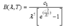 | (4) |
 and
and  which are Planck’s first and second radiation constants, respectively. The actual performance of an absorber at high temperatures may not correspond to the calculated emittance. This is because small errors in measured ρ can lead to large errors in small values of ε[7]. In addition, for some materials the measured emittance data at two different temperatures may simply be different. For example, at
  , the blackbody wavelength maximum for a specific temperature,
 | (5) |
3. Description of Absorber Types
- Selective absorber surface coatings can be categorized into six distinct types: a) intrinsic, b) semiconductor-metal tandems, c) multilayer absorbers, and d) selectively solar-transmitting coating on a blackbody-like absorber. Intrinsic absorbers use a material having intrinsic properties that result in the desired spectral selectivity. Semiconductor-metal tandems absorb short wavelength radiation because of the semiconductor bandgap and have low thermal emittance as a result of the metal layer. Multilayer absorbers use multiple reflections between layers to absorb light and can be tailored to be efficient selective absorbers. Additionally, selectively solar-transmitting coatings on a blackbody-like absorber are also used but are typically used in low-temperature applications. These constructions are shown schematically in Figures 1 a-d, respectively, and are discussed in greater detail below.
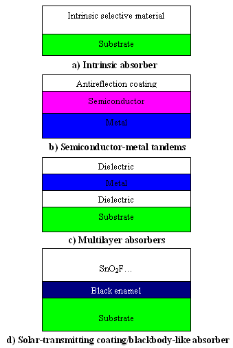 | Figure 1. Schematic designs of four types of coatings and surface treatments for selective absorption of energy |
4. The Materials Used
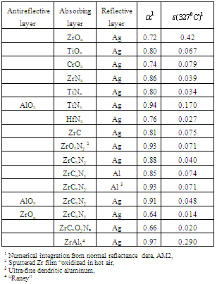
- Titanium, zirconium, or hafnium metal carbides, oxides, and nitrides have a high degree of spectral selectivity. The group IV metal compounds are of the general formula MCxOyNz, M=Ti, Zr, or Hf, and x + y + z <2. In these tandem absorber-reflector films, of the compositions studied, substoichiometric compounds of TiNx, ZrNx, and ZrCxNy (on silver) had the best combination of high solar absorptance and low thermal emittance. The absorptance and emittance calculated from reflectance data are summarized in Table 1[11]. TiNx and ZrNx had nearly identical optical properties, but for HfNx the absorptance was lower and the emittance higher. ZrC was the best pure carbide film. Adding carbon to form zirconium carbonitride (ZrCxNy) increased the solar absorptance by 6%. Oxygen, either as suboxides (TiOx and ZrOx) or substituted into the nitrides and carbonitrides (ZrOxNy or ZrCxOyNz) lowered absorptance and raised emittance. A notable exception was an oxidized Zr film with an absorption of 0.93. Solar absorptance was increased by 8% by replacing the aluminum reflective film with an ultrafine dendritic aluminum. Absorptance was also increased by 5% by the addition of number of samples by normal reflectance and total emittance measurements carried out at elevated temperature. Depending on the sample, there was good agreement with room-temperature measurements up to 400º-600˚C. The thermal stability of these tandem absorber-reflector films was studied, and several absorbers survived cumulative heating periods of 500 h in vacuum up to the maximum test temperature, 700℃[12]. The addition of a thin Al2O3 diffusion barrier improved the stability in air from 125℃ to 175℃[13]. The stability of the tandem films at high temperatures in vacuum was limited to the agglomeration of the metal reflective film, for silver about 350℃. The use of thin layers of Cr2O3, Al2O3, SiO2, or other oxide under the metal has been found to stabilize the silver and aluminum and inhibit agglomeration at high temperatures[14]. Agglomeration has been inhibited at temperatures up to 800℃ for one hour, but the limit of silver stability achieved was about 500℃[15,16]. The selective optical properties of sputtered ZrCxNy on aluminum-coated oxidized stainless-steel are thermally stable from room temperature to 600℃ (likely in vacuum but was not specified)[14]. Sputtered selective absorbers with the structure Al2O3/ZrCxNy/Ag have good optical selectivity with α/εC(325℃)=0.91/0.05 at an operating temperature of 700℃ in vacuum and 175℃ in air[17]. Sputtered ZrOx/ZrCx/Zr absorbers have α/ε(20℃)=0.90/0.05 and are thermally stable in vacuum on stainless-steel and quartz substrates up to 600℃ and 800℃, respectively[16]. “Raney nickel” type alloys were prepared by co-sputtering nickel, zirconium, or molybdenum with aluminum. After the aluminum was etched out of the ZrAl3 film, a very fine open structure resulted that had a solar absorptance greater than 0.95 and a calculated emittance at 327℃ of 0.29[15].
|
5. Developement method of Solar Receiver
- For parabolic trough concentrator solar receiver was developed which has a new selective nanosurface. Solar receiver consists of cylindric pipe with D/d=132/128 mm diameter and 1400 mm length. Beforehand high smooth surface on the pipe was obtained by the polishing machine. Then in the special oven it stays at 60-80℃ temperatures for a while (30-50 sec) for thermal processing and it is cooled. By the specific equipment (SC-400 Precise Coat) the selective layer is covered on the pipe surface in dusting regim. The content of the selective cover consists of Cu+Ni+SiO2+Ni+SiO2 and Cu+Ni+ZnS, its thickness is 0,013-0,058 nm. Hereupon, solar receiver is put into the clear glass. Interstice between metal pipe and glass pipe is vacuumized
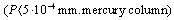 . On the vacuum layer the high temperature forming on the solar receiver surface can’t lose. Maximal limit of the temperature on the receiver surface was 422℃ at 1005 W/m2 solar radiation.
 | Figure 2. Scanning Electron Microscope photomicrograph of selective nano surface texture |
6. Calculation of Concentrator and Solar Receiver System Efficiency
- For solar receiver having parabolic trough concentrator and selective nanocover efficiency is calculated like that:
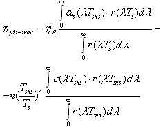 | (6) |
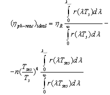 | (7) |
 - temperature of selective nano surface receiving sun rays;
  average temperature of solar surface;
  - spectral quantity of radiant flux density at
  temperature of selective nanocover of the solar receiver;
  spectral quantity of radiant flux density at
  temperature of selective nanocover of the solar receiver;
  and
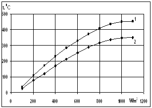
and  - spectral adsorption-irradiant ability mark of solar receiver selective nanocover. The efficiency indexes calculated by this method was given at Figure 3.
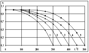 | Figure 3. Dependence of the efficiency on the temperature of solar receiver selective nanocover for different solar radiations (1-200 Wt/m2; 2-400 W/m2; 3-600 W/m2; 4-800 W/m2; 5-1000 W/m2) |
 | (8) |
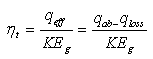
7. Thermal-Energy Calculation of Solar Receiver
- For determining the efficiency of solar receiver having new selective surface heat balance equations are looked through. At stationary regime for solar receiver heat balance equation will be so:
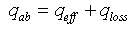 | (9) |
 - effective heat W/m2 absorbed by the heat carrier circling in the internal pipe;
  - the entire heat loss W/m2 from the surface of solar receiver;
  - concentration coefficient of solar energy;
  - integral ray transmission coefficient of glass pipe wall;
  - integral ray absorption of solar receiver;
  - solar radiation W/m2 falling on solar receiver surface. If heat loss from solar receiver surface equals to the heat loss from the glass pipe surface to the environment, then complete heat loss can be determined:
 | (10) |
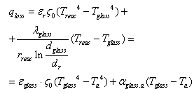 | (11) |
 - heat losses W/m2 happened on solar receiver surface by irradiance;
  - possible convective heat loss W/m2 between solar receiver and glass pipe;
  and
and  irradiation from the glass pipe surface to the environment and heat losses W/m2 by convection;
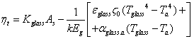
  - blackness rate of selective nanocover on the solar receiver.
  - blackness rate of glass pipe.
  - heat transfer coefficient W/m2 from glass pipe surface to the environment (air);
  - Stefan-Bolsman constant, W/m2 K4;
  - temperatures of glass pipe and air and solar receiver.
  and
and  - diameter of solar receiver and glass pipe.
 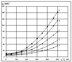 | Figure 4. Dependence of heat losses from solar receiver surface on temperature for several solar radiations (1-200 W/m2; 2-400 W/m2; 3-600 W/m2; 4-800 W/m2; 5-1000 W/m2) |
 | (12) |
 and
and  for (9) and (11) formulas, the indexes are out in the places:
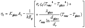 | (13) |
 | (14) |
 | Figure 5. Dependence of solar receiver selective nanocover temperature on solar radiation (1- by vacuum isolation, 2- by without vacuum isolation) |
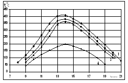 | Figure 6. Dependence of solar receiver selective nanocover temperature change on day hours due to the seasons. Here on the seasons 1- summer, 2-autumn, 3-spring, 4- winter curves were given |
8. Discussion
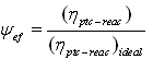
- The technical parameters of the new selective nanocover:● High absorption of solar thermal energy α - 96>98% typical 94% ● Low emittance of infra-red radiation ε = 4>10% typical 7% ● Coefficient of thermal expansion 12.5 x 10⁻⁶ CThese conclusions show that the developed solar receiver having selective nanocover has high effectiveness. So, ray absorption ability is high, heat losses are scanty.
9. Conclusions
- While summarizing the final conclusion such decision was obtained that the developed solar receiver having selective nanocover can be used at the following energy plants absorbers: ● Flat plate solar collectors for both hot water and hot air type.● Parabolic trough and parabolic type collectors.● Vacuum tube type collectors.● Passive heating systems.● A ‘Black’ body requiring low infra-red emittance.
References
| [1] | J.A. Duffie, W.A. Beckman. Solar Energy Thermal Process. Wiley, New York. 2006, p.928. |
| [2] | Mammadov F.F. Solar energy application for purification and treatment of oily waste in oil fields / Tenth World Renewable Energy Congress and Exhibition 2008, 19-25 July, Glasgow, Scotland. pp. 452-455. |
| [3] | F.F. Mammadov. Use of solar energy in Azerbaijan and modern solar energy plants, Progress, Baku, 2011, p.204. |
| [4] | R. B. Pettit, C. J. Brinker, and C. S. Ashley, “Sol-gel double-layer antireflection coatings for silicon solar cells,” Solar Cells, 15, 267 (1985). |
| [5] | A. F. Pereev and N. P. Frolova, “Antireflecting coatings for light-absorbing materials for the 0.4-5 μm spectral region,” Sov. J. Opt. Technol., 41, 8, 453 (1974). |
| [6] | C. Seiffert, T. Eisenhammer, M. Lazarov, R. Sizmann, and R. Blessing, “Test facility for solar selective materials,” ISES Solar World Congress, 2, 321 (1993). |
| [7] | A. Brunotte, M. Lazarov, and R. Sizmann, “Calorimetric measurements of the total hemispherical emittance of selective surfaces at high temperatures,” A. Hugot-Le Goff, C. G. Granqvist, C. M. Lampert, eds., SPIE, 1727, 149 (1992). |
| [8] | R. B. Pettit, “Total hemispherical emittance measurement apparatus for solar selective coatings,” SAND-75-0079, Albuquerque, NM: Sandia National Laboratory, 1975. |
| [9] | S. Brunold, U. Frei, B. Carlsson, K. Möller, and,M. Köhl, “Accelerated life testing of solar absorber coatings: testing procedure and results,” Solar Energy, 68, 4, 313 (2000). |
| [10] | W. S. Duff and L. Hamasaki, “Experimental evaluation of selective surfaces evacuated solar collectors,” R. Campbell-Howe, T. Cortez, and B. Wilkins-Crowder, eds., Proceedings of American Solar Energy Conference, (American Solar Energy Society, Boulder, CO, 1998) p.345. |
| [11] | R. Blickensderfer, “Metal oxycabonitride solar absorbers,” Proc. DOE/DS7 Thermal Power Systems Workshop on Selective absorber coatings, P. Call, ed,. SERI TP-31-061, Golden, CO: Solar Energy Research Institute, 1977, p. 371; R. Blickensderfer, D. K. Deardorff, and R. L. Lincoln, “Spectral reflectance of TiNx and ZrNx films as selective solar absorbers,” Solar Energy, 19, 429 (1977); R. Blickensderfer, U.S. Patent No. 4,098,956, 4 July 1978. |
| [12] | K. D. Masterson and B. O Seraphin, “Investigation of high temperature performance of thin film, solar-thermal energy converters,” Arizona Univ. Optical Science Center, Tuscon, AZ, (1976). |
| [13] | D. M. Mattox and R. R. Sowell, “A survey of selective solar absorbers and their limitations,” Journal de Physique, C1, n1, 42, (1981). |
| [14] | H. Ihara, S. Ebiswa, and A. Itoh, “Solar-selective surface of zirconium carbide film,” Proc. 7th Int. Vac. Cong. and 3rd Int. Conf. on Solid Surfaces, R. Dobrozensky, F. Ruderman, F. P. Viehbock, and A. Breth, eds., (1977) p. 1813. |
| [15] | Y. Noguchi, K. Naka, A. Isao, K. Nakumura, S. Sawada, T. Tani, and S. Gonda, “Fabrication of ZrCx/Zr and Cr-CrOx films for practical solar selective absorption systems,” SPIE, 324, 124 (1982). |
| [16] | M. P. Lazarov and I. V. Mayer, U.S. Patent No. 5,670,248, 23 September 1997; M. P. Lazarov and I.V. Mayer, U S. Patent No. 5,776,556, 7 July 1998. |
| [17] | A. H. Lettington and C. Smith, U.S. Patent No. 5,723,207, 3 March 1998. |
| [18] | 197.C. Z. Deng, K. C. Tsai, and D. Ghantous, U.S. Patent No. 5,980, 977, 9 November 1999. |
| [19] | J. A. Thornton and J. A. Lamb, “Evaluation of cermet selective absorber coatings deposited by vacuum sputtering,” SERI Final Subcontract Report SERI/STR-255-3040, Golden, CO: Solar Energy Research Institute, March 1987. |
| [20] | C.E. Kennedy Review of Mid- to High-Temperature Solar Selective Absorber Materials Technical report July 2002, p 58. |