Rashmi Nawlakha , N. Jasmine , B. Subba Raju , H. Seetha , T. Jayanthi , S. A. V. SatyaMurty
Computer Division, Indira Gandhi Centre for Atomic Research, Department of Atomic Energy, Kalpakkam, 603102, TamilNadu, India
Correspondence to: Rashmi Nawlakha , Computer Division, Indira Gandhi Centre for Atomic Research, Department of Atomic Energy, Kalpakkam, 603102, TamilNadu, India.
| Email: |  |
Copyright © 2012 Scientific & Academic Publishing. All Rights Reserved.
Abstract
One of the key elements considered for safe operation of the Nuclear Power Plant is the knowledge possessed by the operators. Plant safety is ensured by inducting well trained operators and engineers having domain knowledge and experience in the related field. Getting acquainted and trained in the simulator environment definitely yields best results when it comes to handling a crisis or an emergency situation by the operators in a plant. High fidelity Full Scope Simulator plays a major role in providing such training platform for imparting comprehensive training on various plant conditions. Modeling and Simulation of Backup Control Room (BCR) is a part of Prototype Fast Breeder Reactor (PFBR) Operator Training Simulator. This paper discusses about various steps involved in Modeling and Simulation of BCR mainly Virtual panel simulation, the associated logic and control simulation, data collection, naming of process variables, interfacing with the associated processes and integration and testing of BCR with Simulator Environment. The need of BCR in Nuclear Power Plant, its location in plant and various features are also included here.
Keywords:
Nuclear Power Plant, Safety, Prototype Fast Breeder Reactor, Modeling , Simulation, Backup Control Room
1. Introduction
In the present scenario, Full Scope Replica Simulator has become a main component of the operator training programme in Nuclear Power Plant. The replicated control room representing the main control room is used for training the operators to increase the skill sets by providing simulator environment for overall monitoring and control of the plant[1,2]. The operators are trained to operate Main Control Room, Handling Control Room and Backup Control Room for various purposes in the plant.Main Control Room is provided to perform overall monitoring and control of the plant and Handling Control Room is used to carry out fuel handling operations. Diversity and redundancy are also taken into consideration by the Regulatory Authorities to increase the safety of the reactor like Diverse shutdown systems by incorporating Diverse Control Rod Drive Mechanism, Backup Control Room along with the Main Control Room for easy access in case main control room is inaccessible due to fire or some other reason.Modeling and Simulation of Backup Control Room is significant as it helps the operators to understand the indicators and controls provided in BCR and get trained on the panels so that they can take the necessary control actions and initiate safe shutdown of the plant in minimum possible time, incase of any emergency situation which otherwise can lead to a major accident[3,4]. Further, this training will be useful for the periodic functional checking of indicators and controls provided on BCR panels.
2. PFBR Operator Training Simulator
PFBR is a 500 MWe, sodium cooled, pool type reactor based on Mixed Oxide (MOX) fuel, which is first of its kind being built with total indigenous technology at Kalpakkam. To train and qualify the plant personnel without waiting for the commissioning and availability of the reactor, the use of an advanced Operator Training Simulator is inescapable[5]. For PFBR, it is recommended to develop a Full Scope Replica Type Operator Training Simulator which is being built in house at Computer Division of Indira Gandhi Centre for Atomic Research (IGCAR), Kalpakkam.Full Scope Simulator simulates the entire plant operations starting from nuclear core to Turbo generator and Replica type means that the simulator control room and its panels are one to one replica of actual plant control room, down to desks, chairs and lights. The operators are trained to operate Main Control Room (CR), Handling Control Room (HCR) and Backup Control Room (BCR). Figure 1 shows PFBR flow sheet.Figure 2 shows the hardware architecture of PFBR Operator Training Simulator which consists of plant consoles and control panels, Simulation Computer, Input /Output systems, Instructor Station, Simulation Network and Power Supply. Simulation Computer executes various mathematical models of the sub-systems in real time. It takes inputs from control panels and consoles through I/O systems, processes them and responds by giving the information to I/O system for display on indicators, recorders and initiate alarms in real time[6].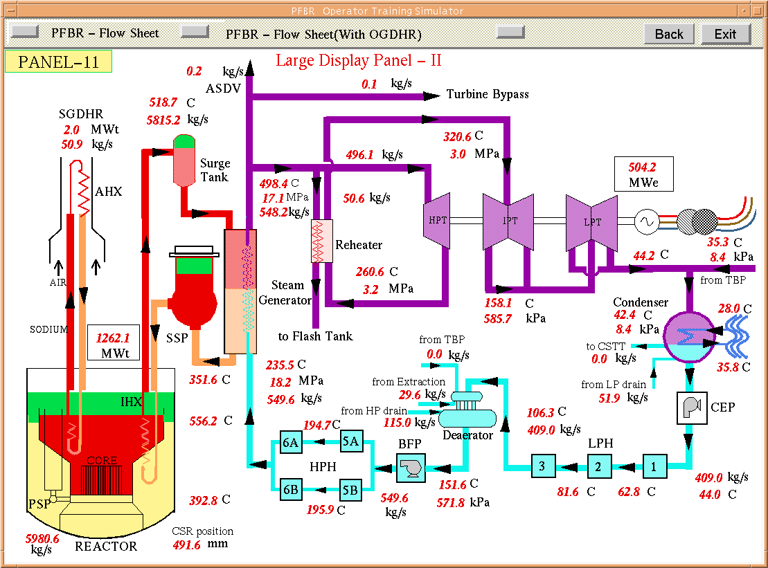 | Figure 1. PFBR Flow sheet |
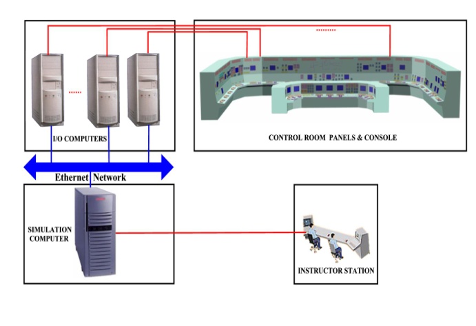 | Figure 2. Hardware architecture |
3. Brief Description of BCR
BCR consists of two conventional panels accommodating indicators, recorders, lamps, control switches, annunciation windows, PC with its accessories, power supply unit etc. When Main Control Room is not available due to some inevitable reasons like fire, the operators will be authorized to perform the necessary safety actions from BCR. BCR is fitted with indicators and controls to monitor relevant parameters to ensure that the reactor is maintained in the safe shutdown state and decay heat is removed. In case normal power supply fails and auto start logic of Diesel Generator (DG) fails, the operator can manually start the DG to provide necessary cooling to the reactor from BCR.BCR is equipped with indicators to monitor neutron flux, control rod position, primary sodium inlet/outlet temperature, primary sodium flow, individual Safety Grade Decay Heat Removal (SGDHR) performance related signals, SGDHR damper status, Diesel Generator (DG) status, primary pump pony motor status etc. Control switches are provided to shutdown the reactor, to operate SGDHR dampers and to start/stop four sets of DG to provide emergency AC power supply to the class III system to drive reactor safety and safety related systems loads.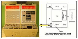 | Figure 3. Location of Backup Control Room |
BCR is located in a building which is physically and electrically separated from Main Control Room. It is possible to reach BCR within 5 minutes. BCR remains unmanned during normal operation[7]. Figure 3 shows the location of BCR in plant.
4. Design & Development of BCR
A Simulation Software is used for development of PFBR Operator Training Simulator. It consists of three basic modules, namely Process Module for Conventional Process Simulation, Logic Module for logic simulation and Virtual Panel Module for creating soft Panels. Modeling of Backup Control Room includes virtual panel modeling as per hardware panel drawings, the associated control and logic simulation and the integration of all these modules with the process models.
4.1. Virtual Panel Development
Virtual panel is the emulation of Hardware panel and this is helpful in the development stage of simulator[8]. Virtual Panel development is carried out using graphics tool which is a part of simulation tool. The virtual panel is divided in three screens like annunciation screen for alarm indication, display screen to monitor various process parameters in required form like analog / digital metes, recorders, lamp indicators etc. and control switches screen to control the reactor status. All the meters, indicators, recorders and control switches are first modeled as submodels. Submodel is an object with the appropriate function written behind it to imitate the real component like analog/digital meters, two / three state selector switches, lamp indications etc. Annunciation, Display and Control Screens are developed by arranging these submodels with proper naming convention according to the design drawings. The annunciation, display and control screen shows the instruments details of the respective panels[9, 10]. Figure 4 shows the virtual panel screens for Backup Control Room panel-1 and 2.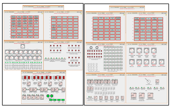 | Figure 4. Virtual panel screens for Backup Control Room panel-1 & 2 |
4.2. Control & Logic Simulation
Logic Model is a control schematic to operate/de-operate the interlocks in all conditions like normal condition, abnormal condition, manual control and automatic control. The control schematics collected from the designers are converted to simulated control logics using basic building blocks and external C code wherever complexity is involved. The logic models take dynamically calculated run time parameters from process models, control inputs from virtual panel models and provides control signals to the process models and display parameters to the virtual panel models. Figure 5 shows the simulated control logic derived from design schematic to operate dampers to remove decay heat of the reactor.The logic is developed to indicate the position (open / crack open / close) of air dampers (Pneumatic / Electrical) of Safety Grade Decay Heat Removal (SGDHR) system. After Reactor SCRAM (shutdown state), SGDHR air dampers come to fully open condition to remove the decay heat automatically. The control switches are provided on BCR panels to open/close the air dampers (Pneumatic / Electrical) manually on failure of automatic action. All the indicators related to SGDHR system available on BCR panel are also integrated[11,12].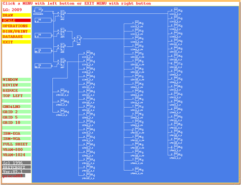 | Figure 5. Simulated control logics |
The logic is developed for a two state selector switch to select Backup Control Room or Main Control Room. on selection of Backup Control Room, the control is transferred to BCR panels thus allowing the operator to do any control operation from BCR panels. On selecting Main Control Room, the control is transferred to CR, the operations cannot be carried out from BCR. The annunciations, display meters and indicators are always enabled independent to the position of BCR/CR selector switch.The logic is developed for a two state selector switch to select BCR in service/out of service. When BCR is in service and BCR selection is done then only control operations from BCR are enabled. To carry out the periodic healthiness testing of BCR panels, BCR out of service is selected to avoid spurious signal to the reactor at normal power operation.The logic is developed to SCRAM (Safety Control Rod Accelerated Movement) the reactor manually. If BCR selection, BCR IN SERVICE selection and MANUAL SCRAM button is pressed then the reactor comes to shutdown state and the SGDHR air dampers will be opened automatically to remove the decay heat.The logic is developed to indicate the healthiness of CLASS IV, CLASS III, CLASS II and CLASS I system buses. The healthiness of the bus is checked by comparing its voltage with the appropriate threshold and the healthy signal is integrated with the lamp indications provided on BCR panel-1. The pony motors for Primary Sodium pumps start/stop indications are also simulated. The logic is developed to give the DG start/stop command from BCR panels after checking BCR selection switch position and BCR in service[13].An external code is developed for Acknowledge, Reset, Alarm test, Lamp Test to incorporate alarm window flashing, audio alarm, clearing alarm and checking the healthiness of all the Digital Output (DO) signals. The standalone testing of the logic model is carried out by changing the test input signals and observing the output signals. After successful testing in standalone mode, these logic models are integrated with the process and virtual panel models.
5. Signal Flow Between Simulator Server and BCR
The important signals coming to BCR are Neutron flux, Air Heat Exchanger (AHX) sodium inlet / outlet temperature, AHX air outlet temperature, sodium flow to AHX, Air inlet/ outlet damper position, air damper control and lamp indications for SGDHR loop-1,2,3 & 4, Manual SCRAM, Control Safety Rod (CSR) / Diverse Safety Rod (DSR) bottom limit, core inlet temperature, core flow, temperature of Central subassembly, channel selection switches for all the display parameters, BCR/CR selection, BCR in service/out of service, indication for healthiness of Class IV, Class III, Class II, Class I systems buses, Two State Start/Stop selector switches of four Diesel Generators, pony motor start/stop indication etc. Figure 6 shows the data flow scheme between simulator server and BCR panels.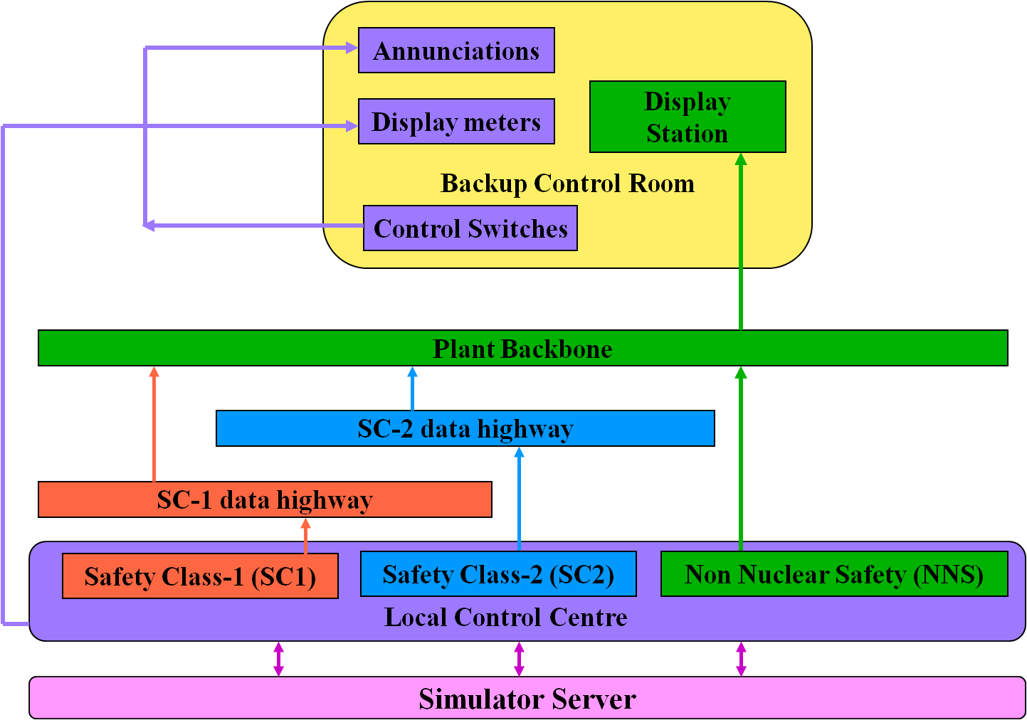 | Figure 6. Data flow from simulator server to BCR |
6. Integration & Testing
Integration is one of the important phase in the design and development of Simulator. This involves integration of process model, logic model and the virtual panel model which is done through a common database in the simulator environment. The simulator environment establishes a communication path among its components through MDSM (Messaging & Data sharing mechanism). A unique variable allocation is done for each signal to establish the proper communication among the developed models[14].BCR Model is integrated with Neutronics system, Primary Sodium system, SGDHR system and Electrical system. Integration includes subscribing the signals from above systems like Neutron flux, primary sodium flow, reactor inlet temp, AHX flow, Class IV bus healthy indication etc. and BCR logic model compares these input parameters with the appropriate thresholds and generate trip signals, open / close signals to and alarm signals. The output processed signals like Reactor SCRAM, DG start/stop, SGDHR damper open/close etc. are connected to their respective systems. Figure 7 shows the integration among all these modules. After all these phases, the most important phase is the testing phase of the model. Integrated testing ensures the proper functioning of BCR model in steady state and transient condition[15].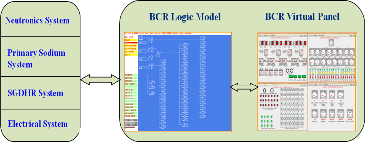 | Figure 7. Integration of BCR Models in Simulator Environment |
7. Commissioning of Hardware Panels of BCR
The developed virtual panels of BCR need to be replaced with simulator hardware panels which are one to one replica of plant BCR. Commissioning of BCR panels include Instrument configuration, Offline/Online Testing, Integration and Testing of panel signals with the developed models. All the panel instruments are configured by setting minimum and maximum ranges according to the design values in the I/O system of the hardware panel. Offline Testing confirms the signal connectivity between I/O System and Hardware panels, Online testing is to check the connectivity between Simulator server to hardware panels through I/O system.Integration and Testing includes replacing virtual panel variables with the hardware panel variables and testing the hardware panel instruments like meters, indicators, control switches etc. during run time. All the meter readings on BCR panels showing different parameters are compared with their design values to confirm the satisfactory performance of the model.
8. Results & Discussions
The virtual panel screens are shown when the SCRAM is initiated from Backup Control Room if any emergency situation occurs.A two state selector (BCR/CR SELECTION) switch is provided to select the Main Control Room or Backup Control Room on Backup Control Room panel-2. For shutting down the reactor through BCR, first BCR selection is done using the selector switch and BCR is in service is also selected then Manual SCRAM command is given by pressing the SCRAM buttons.The bottom limit of CSR and DSR (if these are fully inserted) is displayed on Backup Control Room panel-2. Initiation of MANUAL SCRAM signal leads to falling down of all CSR and DSR to shut down the reactor. Figure 8 shows the MANUAL SCRAM initiation from BCR virtual panel and CSR/DSR bottom limit indication after SCRAM.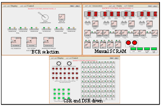 | Figure 8. Manual SCRAM initiation leads to CSR and DSR down |
When reactor comes to shutdown state, SGDHR air dampers comes to fully open position. Figure 9 shows SGDHR air damper position after SCRAM. The yellow lamp indicates the Crack open position of SGDHR air dampers and then red lamp indications confirm the fully open positions of air dampers to remove the decay heat after shutdown. After Reactor SCRAM, the annunciations like SCRAM SLFIT and SCRAM PCSL are also seen on the annunciations panel.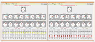 | Figure 9. SGDHR air dampers positions (Crack open and fully open) |
Figure 10 shows the Reactor power profile after SCRAM. The main purpose of Backup Control Room is to safely shutdown the reactor and to remove the decay heat. Both the events are simulated and can be seen in the above result screens.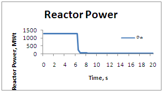 | Figure 10. Reactor power after scram |
9. Conclusions
Backup Control Room Simulator is useful to impart training to PFBR operators in order to operate plant in a safe manner incase of any untoward incident like fire in Main Control Room. The operator can be trained on Backup Control Room Simulator for all the controls provided on it. Operator performance can be evaluated by using instructor station facility and simulating the significant events from instructor station and observing the operator response. The instructor records the activities carried out by trainee after initiating the event and thus imparting full fledged knowledge about backup control room operations.Virtual Panel Modeling for Backup Control Room has been done using Graphic Modeling tool which is a part of the simulation software. Logic Modeling has been carried out for all the associated control logics provided for BCR. BCR virtual panels are integrated with the Process Models and Logic Models. Process models generate all the process parameters every 200ms and gives run time values to logic models where these are compared with appropriate thresholds and then the output is given to virtual panels to show the results in required form like annunciations, display meters, indicators, recorders etc. A log of all the information is also created. The Model is tested with the simulator environment. The results are compared with the design values. It is working satisfactorily.
ACKNOWLEDGEMENTS
The authors gratefully acknowledge the support and guidance provided by the colleagues from Reactor Engineering Group and Nuclear Safety & Engineering Group. The authors are greatly indebted to the constant guidance & motivation provided by Shri. S.C. Chetal, Director, IGCAR.
References
| [1] | Process Simulation of Nuclear Power Plant Using Latest Techniques-T. Jayanthi, S. Rajeswari, K.R.S. Narayanan, H.Seetha, S. Anathanarayanan, S. Athinarayanan, P. Swaminathan - International Journal on Intelligent Electronics Systems, ISSN – 0973-9238, Nov-2007. |
| [2] | T. Jayanthi, H. Seetha,, K.R.S. Narayanan, N. Jasmine, Rashmi Nawlakha, S.A.V Satya Murty, P. Swaminathan " Real Time Simulation and Performance Testing of Process Model of Nuclear Power Plant" ICCMS-2010. |
| [3] | Scope Document for PFBR Operator Training Simulator, T. Jayanthi, S.A.V. SatyaMurty, K.K. Kuriakose, S. Srinivasan, M.L. Jayalal, PFBR/08610/DN/1003/REV-A, IGCAR, 2007. |
| [4] | Training Requirements of PFBR Simulator, T. Jayanthi, S. Rajeswari, PFBR/08610/DN/1008/REV-A, IGCAR,2008. |
| [5] | Operator Training Simulator, T.R. Ellappan, S. Athinarayanan, PFBR/08610/DN/1000/REV-A, IGCAR, 2003. |
| [6] | Hardware Architecture of PFBR simulator, S.A.V. SatyaMurty, P. Shanmugam, Uma Seshadri, PFBR/08610/DN/ 1001/REV-B, IGCAR, 2005. |
| [7] | PFBR Preliminary Safety Analysis Report chapter 8: Instrumentation & Control, 2000. |
| [8] | T. Jayanthi, S. Rajeswari, K.R.S. Narayanan, H. Seetha, S. Ananthanarayanan, "Simulation of Process Model and Control System" 2nd National Conference Mathematical Techniques: Emerging paradigm for Electronics and IT industries, 2008, 125-129. |
| [9] | BCR Panel CPLbc001- General Assembly, PFBR/62620/GA /4101/R 0, IGCAR, 2007. |
| [10] | BCR Panel CPLbc002- General Assembly, PFBR/62620/GA /4103/R 0, IGCAR, 2007. |
| [11] | Design of control logic for dampers of AHX in SGDHR circuit, PFBR/63400/DN/1003/REV-C, IGCAR, 2008. |
| [12] | Operation note on Safety Grade Decay Heat Removal System, PFBR/34000/ON/1001/REV-B, IGCAR, 2005. |
| [13] | Operation Note on Primary Sodium Main Circuit, PFBR/32100/ON/1000/REV-O, IGCAR, 2010. |
| [14] | Software Architecture of PFBR Simulator, R. Jehadeesan, M. L. Jayalal, PFBR/08610/DN/1002/REV-A, IGCAR, 2005. |
| [15] | T. Jayanthi, H. Seetha, K.R.S. Narayanan, N. Jasmine, Rashmi Nawlakha, Bindu Sankar, Jaideep Chakraborty, S.A.V SatyaMurty and P. Swaminathan, "Simulation and Integrated Testing of Process Models of PFBR Operator Training Simulator" Asian Nuclear Prospects 2010, Elsevier, Energy Proceedia 00 (2010) 000-000. |
 Abstract
 Reference
 Full-Text PDF
 Full-Text HTML