Rakhmad Syafutra Lubis
Electrical Engineering, Syiah Kuala University, Banda Aceh, Indonesia
Correspondence to: Rakhmad Syafutra Lubis , Electrical Engineering, Syiah Kuala University, Banda Aceh, Indonesia.
| Email: |  |
Copyright © 2012 Scientific & Academic Publishing. All Rights Reserved.
Abstract
The Generalized Unified Power Flow Controller (GUPFC) is a Voltage Source Converter (VSC) based Flexible AC Transmission System (FACTS) controller for shunt and series compensation among the multiline transmission systems of a substation. The paper proposes a full model comprising of 60-pulse Gate Turn-Off thyristor VSC that is constructed becomes the GUPFC in digital simulation system and investigates the dynamic operation of control scheme for shunt and two series VSC for active and reactive power compensation and voltage stabilization of the electric grid network. The complete digital simulation of the shunt VSC operating as a Static Synchronous Compensator (STATCOM) controlling voltage at bus and two series VSC operating as a Static Synchronous Series Capacitor (SSSC) controlling injected voltage, while keeping injected voltage in quadrature with current within the power system is performed in the MATLAB/Simulink environment using the Power System Block set (PSB). The GUPFC, control system scheme and the electric grid network are modelled by specific electric blocks from the power system block set. The controllers for the shunt VSC and two series VSCs are presented in this paper based on the decoupled current control strategy. The performance of GUPFC scheme connected to the 500-kV grid is evaluated. The proposed GUPFC controller scheme is fully validated by digital simulation.
Keywords:
60-Pulse GTO Thyristor Model VSC, UPFC, GUPFC, Active and Reactive Compensation, Voltage Stability
1. Introduction
The availability of Gate Turn-Off (GTO) thyristor switching devices with high-power handling capability and the advancement of the other types of power-semiconductor devices such as IGBTs have been led to the development of fast controllable active and reactive power sources utilizing power electronic switching and converter technology. A general multi-converter for power system control based on voltage-sourced converter technology was presented. A special three-converter controller with a fundamental frequency model, called the GUPFC, consisting of one shunt and two series converter sharing a common DC bus was modelled in EMTP and its performance demonstrated and analysed. It is shown that the GUPFC can simultaneously control five power system quantities, namely, the real and reactive power flows on the two series compensated lines as well as the sending end bus voltage of the GUPFC[2].The GTO thyristor enable the design of the solid-state shunt reactive compensation and active filtering equipment based upon switching converter technology. These Powers Quality Devices (PQ Devices) are power electronic converters connected in parallel or in series with transmission lines, and the operation is controlled by digital controllers. The interaction between these compensating devices and the grid network is preferably studied by digital simulation. FACTS devices are usually used for fast dynamic control of voltage, impedance, and phase angle of high-voltage ac lines. It devices provide strategic benefits for improved transmission system power flow management through better utilization of existing transmission assets, increased transmission system security and reliability as well as availability, increased dynamic and transient grid stability, and increased power quality for sensitive industries (e.g., computer chip manufacture).The 60-pulse voltage source converter is composed with a series double bridge converter and an auxiliary circuit. The converter is established to increase the number of output voltage pulses and decrease the harmonic distortion of output voltage and current. Without PWM or increasing the number of bridges, the THD of the converter output voltage can be theoretically reduced. By adjusting the connection impedance, the output current can fulfil the THD limit. The proposed configuration only needs one injection transformer, so that phenomenon does not exist. Also, decreasing of transformer number is important for saving cost. The converter is operated under fundamental frequency for the main bridges and six-time fundamental frequency for the auxiliary circuit, while much higher frequency is needed for PWM. By DC voltage injection, the voltage across the main bridge valves, which are being turned on, is theoretically decreased to zero. Thus the converter switching loses and switching device dynamic voltage stress are reduced significantly. This characteristic is very important for high voltage application. The principle of the proposed converter is verified by PSCAD/ EMTDC package[7]. The Interline Power Flow Controller (IPFC) is a VSC based FACTS controller for series compensation with the unique capability of power flow management among the multiline transmission systems of a substation. The reactive voltage injected by individual VSC can be controlled to regulate active power flow in the respective line. While one VSC regulates the DC voltage, the other one controls the reactive power flows in the lines by injecting series active voltage. The circuit model for the IPFC is developed and simulated by using MATLAB simulink and PSPICE[8]The investigation of the dynamic operation of control scheme for both STATCOM and SSSC based on a new full model comprising a 48-pulse GTO voltage source converter for combined reactive power compensation and voltage stabilization of the electric grid network. The complete digital simulation of the STATCOM and SSSC within the power system is performed in the MATLAB/Simulink environment using the Power System Blockset (PSB)[6].This paper proposes the GUPFC in digital simulation system using a cascaded multilevel converter model, where using a 60-pulse (3-levels) VSC that is also introduced in this paper. The VSC described is a harmonic neutralized, 60-pulse GTO converter. It consists of five three-phase, three-level inverters and five phase-shifting transformers. In three 60-pulse voltage source converter, the dc bus is connected to the five three-phase inverters. The five voltage generated by the inverters are applied to secondary windings for shunt VSC of five zigzag phase-shifting transformers connected in or. The five transformer primary windings are connected in series for two series VSC, and the converter pulse patterns are phase shifted so that the five voltage fundamental components sum in phase on the primary side.
2. Gupfc with the 60-Pulse Gto Based Vsc
The basic shunt VSC model consists of a step-down transformer with leakage reactance, a three-phase GTO, and a dc side capacitor. The ac voltage difference across this transformer leakage reactance produces reactive power exchange between the shunt VSC and the power system at the point of interface. The voltage can be regulated to improve the voltage profile of the interconnected power system, which is the primary duty of the shunt VSC. The shunt VSC’s main function is to regulate key bus voltage magnitude by dynamically absorbing or generating reactive power to the ac grid network, like a thyristor static compensator. This reactive power transfer is done through the leakage reactance of the coupling transformer by using a secondary transformer voltage in phase with the primary voltage (network side). This voltage is provided by a voltage-source inverter and is always in quadrature to the VSC current[6].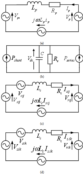 | Figure 1. Equivalent circuit of the GUPFC, (a) the shunt element in the synchronous d-q frame, (b) the AC/DC active power flow, (c) and (d) the series element in the synchronous d-q frame |
The Equivalent circuit of the GUPFC of shunt VSC, series VSC and AC/DC active power flow device can be illustrated in Fig. 1, which is adopted and modified from the UPFC equivalent circuit model[9] become GUPFC equivalent circuit model. Where Vps voltage source, Vp ,represent the output of the shunt transformer and the shunt converter, respectively, ω is the source angular frequency, Lp, Lc and Rp, Rc represent the leakage inductance and resistance of the shunt and series transformer and any other reactors connected, respectively, Vcij, Vcik: the series converter output is represented by a voltage source, Rp, Rc: the resistor is used to represent the power losses in the three converters, C: the value of the DC link capacitor. When the secondary voltage (VS) is lower than the grid system bus voltage (VB), the shunt VSC acts like an inductance absorbing reactive power from the grid bus. When the secondary voltage (VS) is higher than the bus voltage (VB), the shunt VSC acts like a capacitor generating reactive power to the grid bus[3]. In steady-state operation and due to inverter losses, the bus voltage (VB) always leads the inverter ac voltage by a very small angle to supply the required small active power losses.The VSC scheme is the building block of any FACTS devices. A simple converter produces a square voltage waveform as it switches the direct voltage source on and off. The basic objective of a good VSC scheme is to produce a near sinusoidal ac voltage with minimal wave form distortion or excessive harmonics content. Three basic techniques can be used for reducing the harmonics produced by the converter switching[5]. The Harmonic neutralization use magnetic coupling (multi-pulse converters configuration), harmonic reduction using multilevel converter configurations, and novel pulse-width modulation (PWM) switching techniques. The 24- and 48-pulse converters are obtained by combining two or four (12-pulse) VSI, respectively, with the specified phase shift between all converters. For high-power applications with low distortion, the best option is the 48-pulse converter, although using parallel filters tuned to the 23th–25th harmonics with a 24-pulse converter could also be adequately attentive in most applications, but the 48-pulse converter scheme can ensure minimum power quality problems and reduced harmonic resonance conditions on the interconnected grid network[6].The series VSC can work like a SSSC device that is one of the most important FACTS devices for power transmission line series compensation. It is a power electronic-based synchronous voltage generator (SVG) that generates almost three-phase sinusoidal ac voltages, from a dc source/ capacitor bank with voltage in quadrature with the reference line current[5]. The series VSC blocks are connected in series with the transmission line by a series coupling transformer. The series VSC device can provide either capacitive or inductive voltage compensation, if the series VSC-AC voltage lags the line current by 90 , a capacitive series voltage compensation is obtained in the transmission line, and if leads by 90o, an inductive series voltage compensation is achieved[6]. By controlling the level of the boost/buck voltage transmission line, the amount of series compensation voltage can be fully adjusted[1]. The equivalent injected series voltage is almost in quadrature with the reference transmission line current. A small part of this injected voltage , which is in phase with transmission line current, supplies the required losses in the inverter bridge and coupling transformer[4]. Most of the injected voltage is in full quadrature with the reference transmission line current and, hence, emulates an equivalent inductive or capacitive reactance in series with the transmission line[6].
3. Digital Simulation Model
A novel complete model using the 60-pulse digital simulation of the GUPFC within a power system is presented in this paper. The digital simulation is performed using the MATLAB/Simulink software environment and the Power System Blockset (PSB). The basic building block of the GUPFC is the full 60-pulse converter-cascade implemented. The control process is based on a decoupled current control strategy using both the direct and quadrature current components of the shunt and series VSC.A. Power System Description Modelling the unified ac grid sample system with the GUPFC and its decoupled current controller, for the shunt VSC and control scheme for the two series VSC is done using MATLAB/Simulink as shown in Fig. 2. It requires the use of electric blocks from the power system and control blocks from the Simulink power block set library. Detailed Model of a 60-Pulse, GTO-Based GUPFC (500 kV, 100 MVA) device is connected to the 500-kV (L-L) grid network. Fig. 2 shows the single line diagram representing the GUPFC and the host sample grid network. The feeding network are at bus B1 where the voltage source is represented by a 500 kV with 8500 MVA and 300 MW injected load, at bus B3 with 6500 MVA and 200 MW injected load, and at bus B4 with 9000 MVA.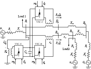 | Figure 2. Three-bus system with the GUPFC at bus B5 and B2 |
Model Description of the GUPFC (detailed model) is used to control the power flow in a 500 kV transmission system. The GUPFC located at the left end of the 200 km line L2, between the 500 kV buses B1 and B5, and 75 km line L1, between the 500 kV buses B1 and B2, is used to control the active and reactive powers flowing through bus B2 and B5 while controlling voltage at bus B1. It consists of three 100-MVA, three-level, 60-pulse GTO-based converters, one connected in shunt at bus B1 and two connected in series between buses B1 and B2, and buses B1 and B5. The shunt and series converters can exchange power through a DC bus. The series converter can inject a maximum of 10% of nominal line-to-ground voltage (28.87 kV) in series with line L1 and L2. According to the simulation mode of operation as well as the reference voltage and reference power values can be changed by means of the “GUPFC GUI” block. When the three converters are operated in GUPFC mode, the shunt converter operates as a STATCOM. It controls the bus B1 voltage by controlling the absorbed or generated reactive power while also allowing active power transfer to the two series converters through the DC bus. The reactive power variation is obtained by varying the DC bus voltage. The five three-level shunt converters operate at a constant conduction angle (Sigma= 180-7.5 = 172.5 degrees), thus generating a quasi-sinusoidal 60-step voltage waveform. The first significant harmonics are the 59th and the 61th. When operating in GUPFC mode, the magnitude of the two series injected voltage are varied by varying the Sigma conduction angle, therefore generating higher harmonic contents than the shunt converter. As illustrated in the simulink, when the series converter operates in SSSC mode it generates a “true” 60-pulse waveform.The natural power flow through bus B5 and B2 when zero voltage is generated by the two series converter (zero voltage on converter side of the five converter transformers) is P=+870 MW and Q= -70 Mvar. In GUPFC mode, both the magnitude and phase angle and the two series injected voltages can be varied, thus allowing control of P and Q. The GUPFC controllable region is obtained by keeping the injected voltage to its maximum value (0.1 pu) and varying its phase angle from zero to 360 degrees.The GUPFC device comprises the full 60-pulse voltage source converter-cascade model connected to the host electric grid network through the coupling transformer. The dc link voltage is provided by the capacitor C. The decoupled current control system ensures full dynamic regulation of the bus voltage (VB), the series voltage injected and the dc link voltage VDC. The 60-pulse VSC generates less harmonic distortion and, hence, reduces power quality problems in comparison to other converters such as (6, 12, 24 and 36) pulse. This results in minimum operational overloading and system harmonic instability problems as well as accurate performance prediction of voltage, active and reactive power flow and dynamic stability conditions.B. 60-Pulse GTO Based VSCFive 12-pulse GTO-converters, phase-shifted by 7.5o from each other, can provide the full 60-pulse converter operation. Using a symmetrical shift criterion, the 7.5o are provided in the following way: phase-shift winding with -3.75o on the two coupling transformers of one 24-pulse converter and +3.75o on two transformers of the second 24-pulse converter and addition one phase-shift winding with -3.75o on the one coupling transformers of one 12-pulse converter The firing pulses need a phase-shift of +3.75o, respectively. The 60-pulse converter model comprises five identical 12-pulse GTO converters interlinked by five 12-pulse transformers with phase-shifted windings. Fig. 3 depicts a schematic diagram of the 60-pulse GTO converters model for shunt VSC, where advanced from 48-pulse GTO as introduced in[5] and with the same method can be found for series VSC. The transformer connections and the necessary firing-pulse logics to get this final 60-pulse operation are modelled. The 60-pulse converter can be used in high-voltage high-power applications without the need for any ac filters due to its very low harmonic distortion content on the ac side. The output voltage have normal harmonic , where r=0,1,2,3 ,i.e.
 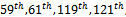 with typical magnitudes
 , respectively, with respect to the fundamental; on the dc side, the lower circulating dc current harmonic content is the 60th.The phase-shift pattern on each five 12-pulse converter cascade is as follows.
  | Figure 3. Sixty-pulse GTO’s VSC of GUPFC shunt controller |
1st 12-Pulse Converter: The resultant output voltage generated by the first 12-pulse converter is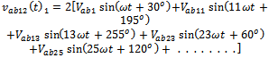 | (1) |
2nd 12-Pulse Converter: The resultant output voltage generated by the second 12-pulse converter is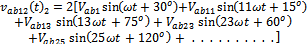 | (2) |
3rd 12-Pulse Converter: The resultant output voltage generated by the third 12-pulse converter is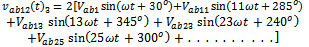 | (3) |
4th 12-Pulse Converter: The resultant output voltage generated by the fourth 12-pulse converter is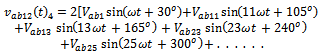 | (4) |
5th 12-Pulse Converter: The resultant output voltage generated by the fourth 12-pulse converter is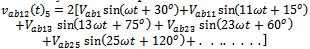 | (5) |
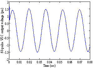 | Figure 4. Sixty-pulse VSC output voltage |
These five identical 12-pulse converters provide shifted ac output voltages, described by (1)–(5), are added in series on the secondary windings of the transformers. The net 60-pulse ac total output voltage is given by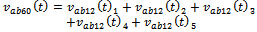 | (6) |
 | (7) |
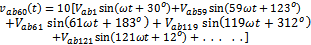
The line-to-neutral 60-pulse ac output voltage from the VSC model is expressed by | (8) |
 | (9) |
Voltages  and
and  have a similar near sinusoidal shape with a phase shifting of 120o and 240o, respectively, from phase a
 . Fig. 4 depicts the net resultant 60-pulse line-to-line output voltage of the 60-pulse GTO-Converter scheme.
4. Dynamic Performance of the Gupfc
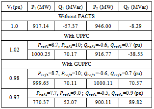
The simulation is carried out by using the MATLAB- Simulink and power system blockset[10], where the digital simulation results are given as shown in Fig. 5 and 6.A. DemonstrationDemonstration of power control in GUPFC mode is in the GUPFC GUI block menu. The GUI allows to choose the operation mode (GUPFC, STATCOM or SSSC) as well as the Pref/Qref reference powers and/or Vref reference voltage settings. Also, in order to observe the dynamic response of the control system, the GUI allows specifying a step change of any reference value at a specific time. Make sure that the operation mode is set to “GUPFC (Power Flow Control)”. The reference active and reactive powers are specified in the last two lines of the GUI menu. Initially, Pref=+8.7 pu/ 100MVA (+870 MW) and Qref=-0.6 pu/100MVA (-60 Mvar). At t=0.25 sec Pref is changed to +10 pu (+1000MW). Then, at t=0.5 sec, Qref is changed to +0.7 pu (+70 Mvar). The reference voltage of the shunt converter (specified in the 2nd line of the GUI) will be kept constant at Vref=1 pu during the whole simulation (Step Time=0.3*100) and (Simulation stop time=0.8 sec). When the GUPFC is in power control mode, the changes in STATCOM reference reactive power and in SSSC1 and SSSC2 injected voltage (specified respectively in 1st, 3st and 4rd line of the GUI) as are not used.Table 1. voltage in bus 1 and power flow in line 1 and 2
 |
| |
|
The simulation was run for 1 sec. In the “Show Scopes” subsystem, Observe on traces 1 and 2 of the GUPFC scope the variations of P and Q. After a transient period lasting approximately 0.18 sec, the steady state is reached (P=+87 pu; Q=-0.6 pu). Then P and Q are ramped to the new settings (P=+10 pu Q=+0.7 pu). Observe on traces 3 and 4 the resulting changes in P Q on the three transmission lines. The performance of the shunt and series converters can be observed respectively on the STATCOM and SSSC scopes.B. Simulation ResultsA relatively large DC capacitor of 2500pF is used due to the large power demanded by the series converter at some operating conditions. System start of the shunt VSC was simulated first and then reactive reversal was examined. Before the system starts, it is assumed that the DC link capacitor have been initially charged to their desired values. Figs. 5 show the simulated waveforms when the shunt system started with the reference voltage control being (1.0pu and 1.005pu). The DC voltage is well controlled with a normal ripple and so that voltage at bus-1 can be controlled. The simulated results of power flow control by the GUPFC system are shown in TABLE I and Fig. 6 and 7 where shows the waveforms with Pref=8.7pu; 10pu and Qref= -0.6pu; 0.7pu for the first case and with Pref=7.7pu; 9.0pu and Qref=-0.5pu; 0.9pu for the second case. As shown, after the series element of the GUPFC is started at the time of 0.25 s, the active and reactive power flows were restored to the reference values and fully controlled by the GUPFC. The responses are satisfactory for both starts, although relatively small gains have been used for the controller. The response time is normally within one fundamental cycle and the fluctuation of the active and reactive power relatively is small, while have ramped at Pref=10pu and Qref=0.7pu, or Pref=9pu and Qref=0.9pu for the second case indicates changing according to the adjusting. The DC voltage control of the shunt VSC during transient operation of the series VSC was tested and Figs. 5, 6 and 7 shows the simulated results. After the series converter started at 0.25 s, the transmitted active and reactive powers are restored to their reference value, while the current of the shunt VSC responds accordingly to maintain a constant DC link voltage. As the series converter absorbs active power at this operating mode (and indeed it has to be fed back to the network by the shunt VSC), the phase angle between the shunt current and voltage becomes less than 90o. This indicates active power transmitted from the DC side back to the AC side by the shunt VSC that provides independent voltage control being (1.0pu and 1.005pu). In Fig. 6 (a) and (b) can be shown response of Pref=8.7pu becomes 10pu and Qref=-0.6pu becomes 0.7pu for the two lines, where another line goes with less increase than initial condition to find the steady- state condition. In Fig. 7 (b) and (c) also can be shown response of Pref=7.7pu becomes 9pu and Qref=-0.5pu becomes 0.9pu for the two lines, where another line goes with less increase than initial condition by few different with the above to find the steady- state condition.Fig 6 (d) and (e) show the active and reactive power run following the reference value, this indicate that the simulation, power system, scheme is working with good performance. Fig 7 (d) and (e) show the same performance as above with a changing.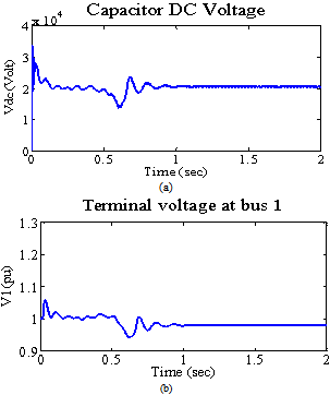 | Figure 5. Simulated results of the GUPFC .shunt converter operation for DC voltage with Qref = 0.3pu; 0.5 pu |
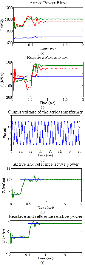 | Figure 6. Simulated results of the GUPFC series converter operation Pref=8.7pu; 10pu, Qref=-0.6pu; 0.7pu |
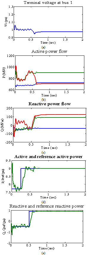 | Figure 7. Simulated results of the GUPFC series converter operation Pref=7.7pu; 9.0pu, Qref=-0.5pu; 0.9pu |
5. Effects of the Power System Strength on the Shunt Vsc Stability
If the impedance of the power system increases (weak system), the amount of voltage change due to the shunt VSC reactive current increases, and the overall system moves to instability. If the power system impedance decreases (strong system), the system is more stable, although the dynamic response is slower than that for a weak system. Therefore, the power system strength greatly affects the response time and stability of the shunt VSC. If the voltage regulator is set to provide a fast response for a strong system, it may lead to possible instability for a weak power system, while if the voltage regulator is set to provide a stable response for a weak system, the response for a strong power system will be very slow and sluggish as the over power system closed-loop gain decreases[6].To check the effect of the power system strength on the shunt VSC stability, the digital simulation is carried out again for the proposed system shown in Fig. 2. In this case, the loads of this power system are replaced with new loads, which are Load 1 (P=3pu and Q=0.7pu; inductive parallel load Y grounded) and load 2 (P=2pu and Q=0.6; inductive series load Y grounded). This new system is investigated when load 1 is rejected at T=0.5s and only load 2 remains connected. Both control schemes were validated in order to show the effects of the GUPFC control based on decoupled current control system switching technique in damping oscillations and suppressing the transient system transients.a) Digital Simulation ResultsThe digital simulation is carried out for the new system with both loads 1 and load 2 connected and the GUPFC is switched at 0.1s. The load excursion occurred at 0.5s by fully disconnecting load 1. This load excursion leads to the weak power system. The controller scheme are validated under this condition in order to show their capability in keeping the GUPFC stable for a weak power system.Figs. 7 show the dynamic performance for controller and their effectiveness for power system stability. After 0.5s the system is going to go through dynamic condition with more peak overshoot and then the system is going to a settling time before 1.0s and then finding a steady state condition at 1.0s. This performance can be seen in each figure where the controller scheme have given its robust contribution for reach the final system stability under this condition in order to show their capability in keeping the GUPFC stable for a weak power system With the load excursions, the digital simulation results show that the decoupled current control switching technique provides higher dynamic performance for a weak power system by damping any oscillations and suppressing transients. In addition, for the GUPFC stability, this controller scheme is also enhancing the power transfer due to high efficiency in voltage stabilization and proving instant reactive power compensation with shunt VSC.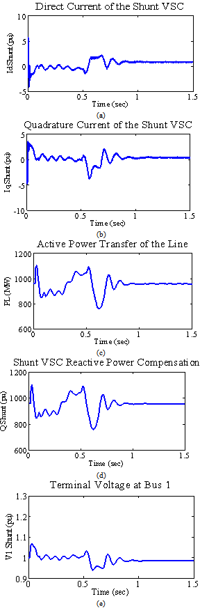 | Figure 7. Digital simulation results for the decoupled current controller schemes for the shunt VSC in a weak power system |
6. Conclusions
The paper presents and proposes a novel full 60-pulse GTO voltage source converter that it constructed becomes GUPFC FACTS devices. It comprises the full 60-pulse VSC-cascade models connected to the grid network through the coupling transformer. These full descriptive digital models are validated for voltage stabilization, active and reactive compensation and dynamically power flow control using three decoupled current control strategies. The control strategies implement decoupled current control switching technique to ensure controllability, minimum oscillatory behaviour, minimum inherent phase locked loop time delay as well as system instability reduced impact due to a weak interconnected ac system and ensures full dynamic regulation of the bus voltage (VB), the series voltage injected and the dc link voltage Vdc. The 60-pulse VSC generates less harmonic distortion and reduces power quality problems in comparison to other converters such as (6,12,24 and 36) pulse.In the synchronous reference frame, a complete model of a GUPFC has been presented and control circuits for the shunt and two series converters have been described. The simulated results presented confirm that the performance of the proposed GUPFC is satisfactory for active and reactive power flow control and independent shunt reactive compensation.
AcknowledgEmentS
The authors would like to thank for the support and helpful comments of academicals members Gadjah Mada University for this work.
References
| [1] | K. K. Sen, “SSSC-static synchronous series compensator. Theory, modeling and application”, IEEE Transactions on Pwer Delivery, Vol. 13, No. 1, pp. 241-246, January 1998. |
| [2] | B. Fardanesh, B. Shperling, E. Uzunovic, and S. Zelingher, "Multi-Converter FACTS Devices: The Generalized Unified Power Flow Controller (GUPFC)," in IEEE 2000 PES Summer Meeting, Seattle, USA, July 2000. |
| [3] | N. G. Hingorani and L. Gyugyi, “Understanding FACTS, Concepts and Technology of Flexible AC Transmission Systems. Pscataway, NJ: IEEE Press. 2000. |
| [4] | X. P. Zang, “Advanced Modeling of the Multicontrol Functional Static Synchronous Series Compensator (SSSC) in Newton Power Flow” , IEEE Transactions on Power Systems, Vol. 20, No. 4, pp. 1410-1416, November 2005, |
| [5] | A. H. Norouzi and A. M. Sharaf, Two Control Schemes to Enhance the Dynamic Performance of the Statcom and Sssc”, IEEE Transactions on Power Delivery, Vol. 20, No. 1, pp. 435-442, January 2005. |
| [6] | M. S. El-Moursi, A. M. Sharaf, “Novel Controllers for the 48-Pulse VSC StatCom and SSSC for Voltage Regulation and Reactive Power Compensation”, IEEE Transactions on Power Systems, Vol. 20, No. 4, pp. 1985-1997, November 2005. |
| [7] | W. Pan, Z. Xu, and J. Zhang, “Novel configuration of 60-pulse voltage source converter for StatCom application” International Journal of Emerging Electric Power Systems, Vol 8, Issue 5, Article 7, 2007. |
| [8] | A. P. U. Rani and B. S. R. Reddy, “Modeling and Digital Simulation of Interline Power Flow Controller System”, International Journal of Computer and Electrical Engineering, Vol. 2, No. 3, 1793-8163, pp. 441-446, June, 2010. |
| [9] | L. Xu and V. G. Agelidis,” Flying capacitor multilevel PWM converter based UPFC”, IEE hoc.-EIects Power. Appl., Vol. 149, No 4, pp. 304-310, July 2002. |
| [10] | Matlab Programming, 2005. Available in: www.mathworks. com. |
 Abstract
 Reference
 Full-Text PDF
 Full-Text HTML