-
Paper Information
- Previous Paper
- Paper Submission
-
Journal Information
- About This Journal
- Editorial Board
- Current Issue
- Archive
- Author Guidelines
- Contact Us
International Journal of Energy Engineering
p-ISSN: 2163-1891 e-ISSN: 2163-1905
2012; 2(2): 15-22
doi: 10.5923/j.ijee.20120202.03
Implementation of Digital Signal Controller TMS320C28027 Based PWM for A Single Phase Bidirectional High Frequency Link Photovoltaic Inverter
 Abstract
 Reference
 Full-Text PDF
 Full-Text HTML
Prashant V. Thakre 1, Saroj Rangnekar 2
1Electronics & Telecommunication, SSBT’s COET, Jalgaon, 425001, India (North Maharashtra University)
2Department of Energy, MANIT, Bhopal, 462051, India (MANIT,Bhopal)
Correspondence to: Prashant V. Thakre , Electronics & Telecommunication, SSBT’s COET, Jalgaon, 425001, India (North Maharashtra University).
| Email: |  |
Copyright © 2012 Scientific & Academic Publishing. All Rights Reserved.
PV grid connected and stand alone systems are becoming more and more popular now a days.With proper tracking system an efficient inverter system can be developed for single phase as well as three phase.This research paper is basically based on the approach that by considering a conventional tracking system a single phase inverter circuit is implemented whose switching is done by using DSP TMS320C28027.
Keywords: photovoltaic panels, boost converter , bridge inverter, unipolar pwm switching, TMS320C28027
Article Outline
1. Introdction
- Continuous efforts are being made to reduce green house emission by using alternative sources of energy. Due to which photovoltaic energy is gaining more attention in research field. One of the major area where it is gaining more importance is usage of this energy as an alternative for conventional electrical energy. For generating electrical energy it is necessary to use proper tracking system for harvesting the photovoltaic energy and then using an appropriate inverter for converting the stored DC signal into a proper AC signal with reduction in harmonics. For tracking system the most commonly used technique is MPPT algorithm where maximum power is extracted when the voltage and current is maximum for a photovoltaic panel[1]. Commonly used algorithms include Perturb and Observation method (P&O) and Incremental Conductance method (ICM) [2]. P&O method perturb the solar array voltage in one direction at each sampling period and tests the power change afterwards. The incremental conductance method calculates the derivative of power to get correct direction for perturbing the arrays reference variable[3].For any type of inverter pulse width modulation is the most powerful technique which offers a convenient method for controlling the analog output generated through digital signal processor. With the availability of low cost high performance digital signal processors, it is easily possible to control the output of single phase photovoltaic inverter by adjusting or controlling the switching frequency or switching time of the power device with altering the PWM signal through digital signal processor. Controlling methods can be broadly classified as current control and voltage control. But both the methods ultimately controls the sinusoidal output generated through inverter circuit[4]. For obtaining a smooth sinusoidal signal with reduced harmonics contents, the duty cycle of the PWM signal is varied .The variation in duty cycle is achieved by implementing a closed loop system where the output current or output voltage is continuously monitored and controlled by digital signal processor according to which switching time of power device is adjusted. This results in a smooth sinusoidal signal with less harmonic contents[5].This research paper presents a theoretical and experimental approach for implementation of digital signal processor in a single phase bidirectional high frequency link photovoltaic inverter. This proposed method offers an advantage of using a cheaper and effective digital signal processor TMS320C28027 from Texas Instrument for generating PWM signal for a photovoltaic single phase inverter. This method in addition also offers an advantage of doubling the switching frequency of the inverter voltage by using unipolar switching technique, due to which design of output filter becomes easier and also the cost and size is reduced. In addition to the above advantages, if a bidirectional high frequency link photovoltaic closed loop inverter is used, then it provides an additional feature of improving the output signal by reduction in harmonics.
2. Implementation of Tracking System
- The most commonly used MPPT algorithm is Purterb and observe method which is more convenient to implement. P&O method is based on the calculation of PV array output power and the power change by sensing both photovoltaic voltage and current. The tracker operates periodically by comparing the actual detected value of the power with the previous value to determine the change in solar voltage. To achieve such type of perturbations a stepper motor can be implemented which moves as per the step size generated after comparing the present value with previous value. The P&O method can be explained with the algorithm shown in fig.1.1.
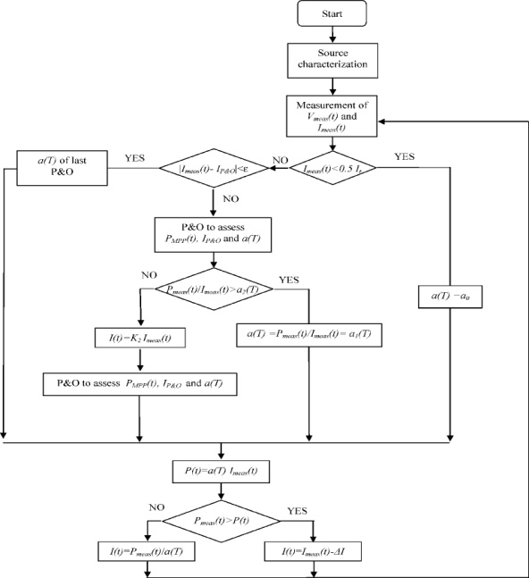 | Figure 1.1. |
 | Figure 1.2. |
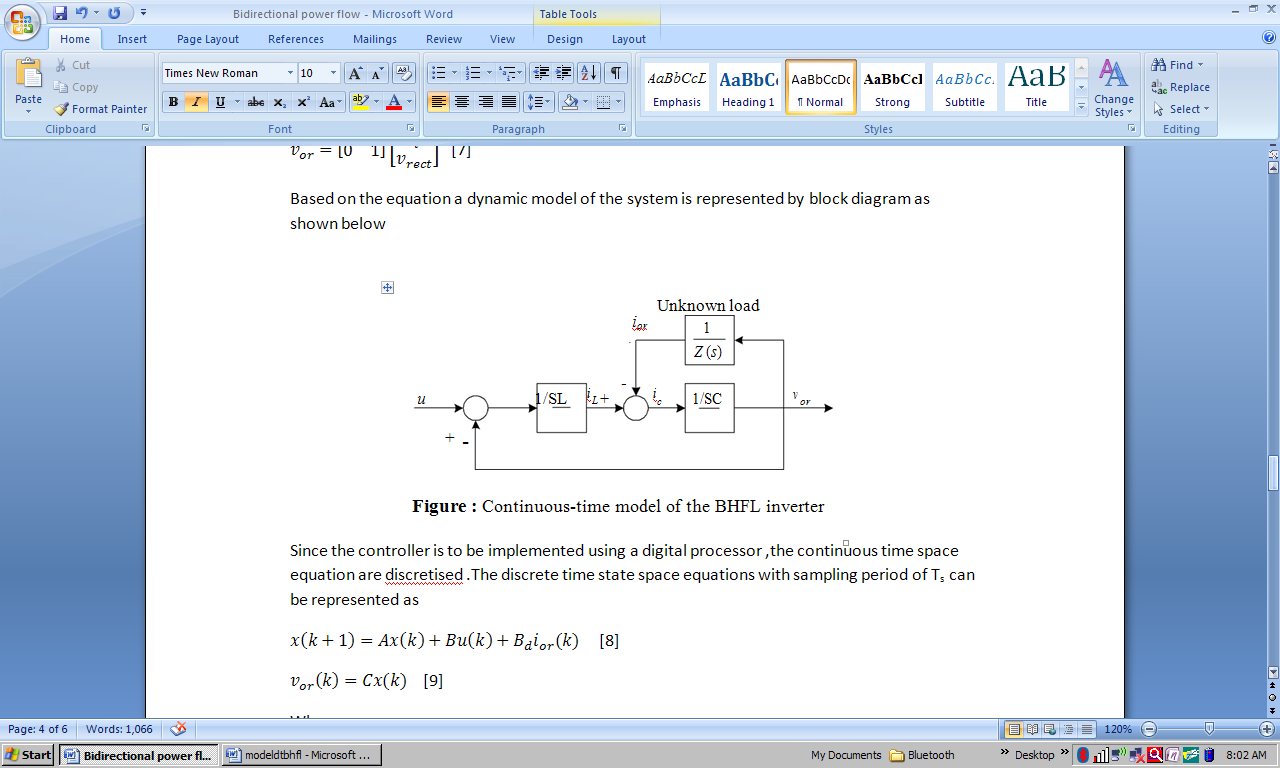
3. Modeling of Closed Loop Inverter
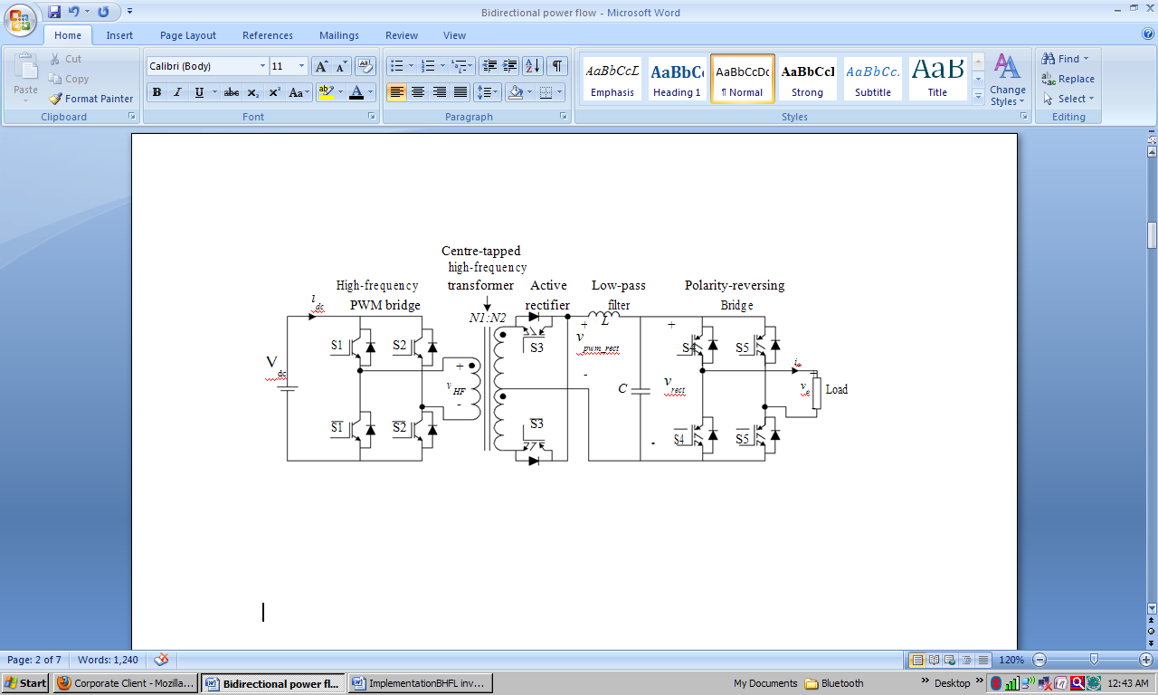
- To design a closed-loop controller for the BHFL inverter, a dynamic model of the BHFL inverter is first derived. State-space technique is used to model the inverter.Referring to Figure 1.2, it is assumed that the dc source voltage, Vdc is constant. The inverter switching frequency is considered to be much higher than the 50Hz sinusoidal modulating frequency. The high-frequency transformer is assumed to be operating in the linear area. As such, the high-frequency PWM bridge and the transformer can be modeled as constant gains. The polarity-reversing bridge is only operated at line-frequency (50Hz), thus its dynamics can be ignored. With these assumptions, the dynamics of the system can be simplified to a LC low-pass filter connected to the load. Figure 1.3 depicts the equivalent circuit of the BHFL inverter, where u is the system input (control variable), and Z denotes the output impedance of an unknown load. The Equivalent Series Resistance (ESR) of the filter inductor is denoted as rL, and the ESR of the filter capacitor is denoted as rc.
 | Figure 1.3. |
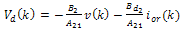
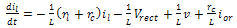 | (1) |
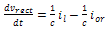 | (2) |
 | (3) |
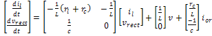 | (4) |
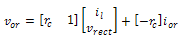 | (5) |
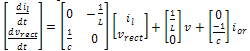 | (6) |
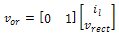 | (7) |
 | Figure 1.4. |
 | (8) |
 | (9) |
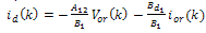
|
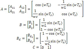
 is the state vector &
  is the cut off frequency of the low pass filter in radians/second.From equation 8 and 9, the discrete time equation can be rewritten as:
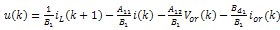 | (10) |
 | (11) |
 | (12) |
 | (13) |
 | Figure 1.5. |
4. System Implementation
- Generating DC signal using MPPT system:-Based on the above theory a tracking system has been developed by using MATLAB/simulink as shown in figure 1.6The figure shows a simulink model of a PV array consisting of 6 PV modules in series.In this model all module share equal current Ipv .It is assumed that all modules have same insolation of 1000 watt/m2.The pv module parameters are the short circuit current Isc and open circuit voltage Voc as well as rated current at maximum power point and rated voltage at standard test condition.
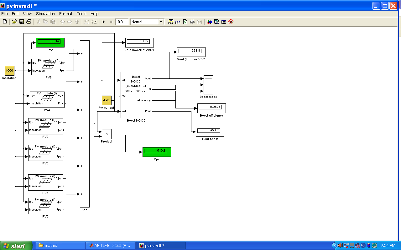 | Figure 1.6. |
 | Figure 1.7. |
5. Generation of PWM Signal Using TMS320c28027
- Generation of PWM signal is based on the performance of digital signal processor. For this, processor TMS320C28027 of Texas Instrument has been selected. It is a piccolo series processor which is coupled with highly integrated control peripherals in low pin count devices. It is a high efficiency processor with 32 bit CPU and having frequency of 60MHz, 50MHz and 40MHz respectively. It is also having ON-Chip flash, SARAM and OTP memory. It consists of analog comparators with 10 bit reference and can be routed directly to control PWM outputs.This processor is also cheaper and easy to implement.Generation of PWM signal is based on implementation of algorithm, preparing of source code in C or C++ and compiling,building and running the source code in code composer studio.The version used for code composer studio is 3.1 and the PWM signal has been generated at 8 GPIO pins i.e from GPIO0 to GPIO7 by continuously comparing the output voltage or current received by inbuilt ADC. The PWM signals generated from GPIO pins are applied to the IGBT’s of inverter circuit through a driver circuit.
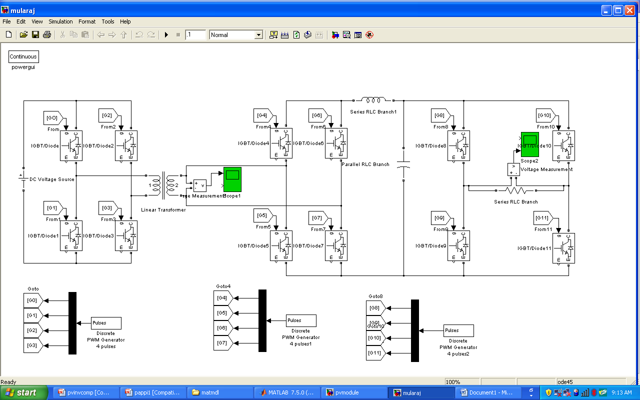
6. Modeling of BHFL Inverter Using MATLAB/Simlink
- The inverter model used for simulation is a pulse width modulated inverter as shown in Fig.6. In such type of inverter, the input DC voltage from a solar tracker or battery which is constant in magnitude, is applied to the inverter circuit. The inverter circuit consists of switching devices such as IGBT, MOSFET which rectifies the output voltage.Thus the inverter must control the magnitude and frequency of the generated AC signal. This is achieved by using pwm technique. The type of switching used in model is unipolar switching. In pwm with unipolar switching, the two legs of full bridge inverter are not switched simultaneously. The two legs are controlled separately by comparing the modulating signal (Vmod) and carrier signal (Vref).1. If Vmod > Vref then G1is ON and Vo=Van2. If Vmod < Vref then G2 is ON and Vo=03. If –Vmod > Vref then G3 is ON and Vo=Vbn4. If –Vmod < Vref then G4 is ON and Vo=0Vo = Van – Vbn Thus G1 and G4 is ON, Van=Vd,Vbn=0 then Vo = VdG2 and G3 is ON, Van=0, Vbn=Vd then Vo=-VdG1 and G3 is ON, Van=0, Vbn=0 then Vo=0G2 and G4 is ON, Van=0, Vbn=0 then Vo=0Thus when switching occurs , the output voltage changes between 0 and +Vd as well as 0 and –Vd voltage levels.This is called as unipolar switching.The unipolar switching has advantage of doubling the switching frequency which results in cancellation of harmonics.
7. Simulation Result
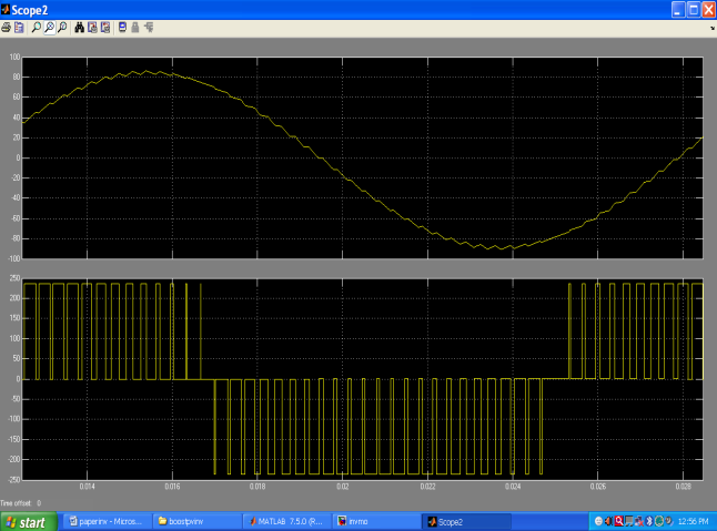
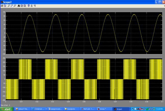
- The performance of photovoltaic inverter was tested using MATLAB and the output signal was observed with different carrier frequencies as shown in fig 1.8(a),(b) and (c).
7.1. Analysis of Photovoltaic Model
- Insolation = 1000 w/m2Ratings of PV cell (with bypass diode)Voc= 22.2 volts, Isc = 5.45AmpVoltage at Pmax =17.2 volts, Current at Pmax = 4.95 AmpOutput dc voltage = 103.2 volts
7.2. Analysis of Boost Converter
- Input dc voltage = 103.2 voltsInductance (L) = 2mHLoad Resistance (Rl) =2KOutput dc Voltage = 235.6
7.3. Analysis of Inverter Model
- PWM Generation: - Sampling Time = 2μsecModulating Signal: - Modulation Index = 0.8Frequency = 60 HzInput dc signal = 235.6
8. Output Signal
- Carrier Frequency =1.5 KHz
 | Figure 1.8(a). |
 | Figure 1.8(b). |
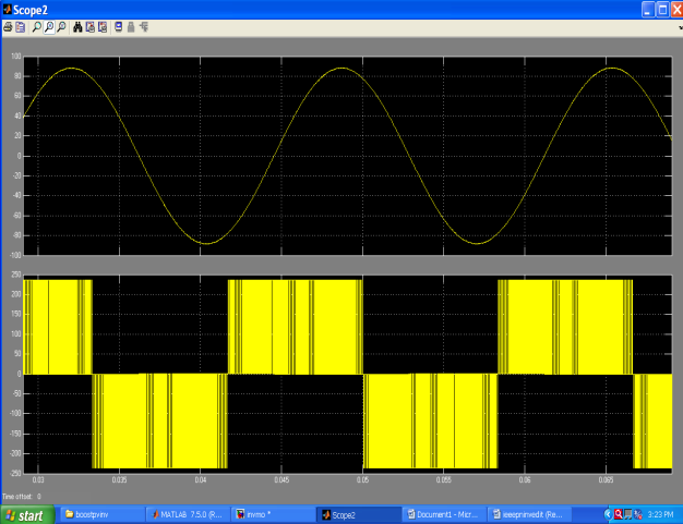 | Figure 1.8(c). |
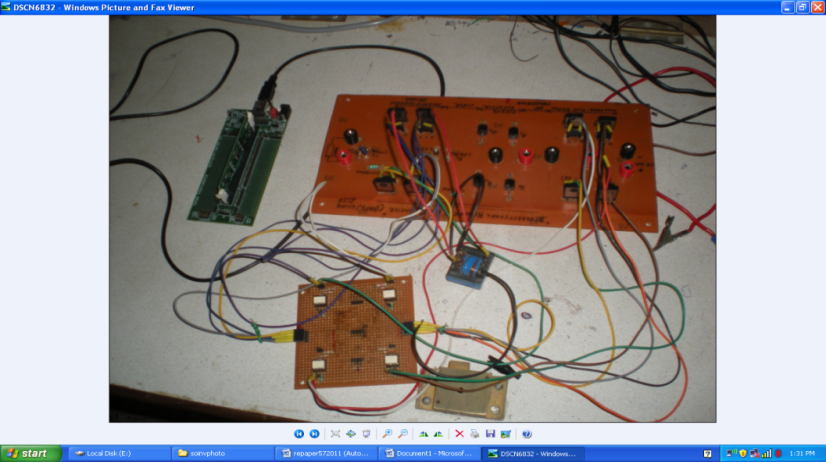
9. Hardware Implementation
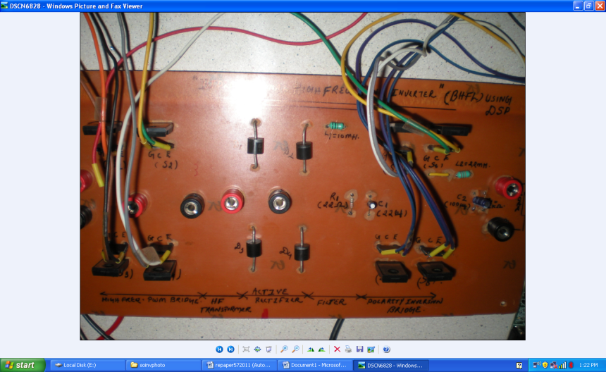
- A photovoltaic bidirectional link inverter was implemented using a solar tracker .An inverter circuit with a filter, driver circuit with processor tms320c28027 was developed and tested with a conventional solar tracker.The specification of hardware is as follows:-Specification of PV moduleModel – SLP5-12, Rated Power :- 5wattRated Voltage: -17volt,Rated Current: -0.29 AmpO.C voltage: - 21.6 volts,S.C current: - 0.34 AmpStandered Test Condition – 1000watt/m2Battery specificationMicrotek: - 12 volt, 7.2 AhInverter circuit specificationIGBT Driver: - TLP 250IGBT: - G4PC60UFilter Circuit: - Inductor-10mH, Resistance – 22 ohms, Capacitor – 22 microfaradA solar tracker as shown in Fig.1.9 was designed to charge a 12 volt, 7 amp battery. The solar tracker was able to track the sun from east to west based on the LDR circuit by rotating the PV module with 22.5 degree at every 3 hours to get maximum power.
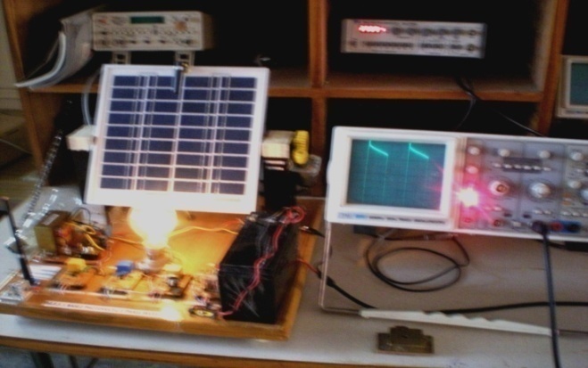 | Figure 1.9. |
 | Figure 1.10. |
 | Figure 1.11. |
10. Output Signals Observed
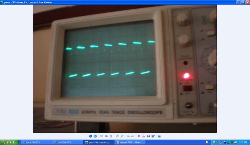
- PWM Signal: -PWM signal for switching of IGBT was generated from a driver circuit consisting of IC TLP250. The input to driver circuit was given from the GPIO 1 to GPIO4 pins of processor TMS320C28027. The PWM signal throughTMS320C28027 was generated by loading,debugging and building the program in code composer studio (version 3.1). The PWM signal generated is shown in fig.1.12.
 | Figure 1.12. |
 | Figure 1.13. |
11. Conclusions
- This paper presents the simulation and hardware of a single phase photovoltaic BHFL inverter using TMS320C28027control. It is observed in simulation that with the increase in frequencies the nature of the ac signal can be improved. Further, the implementation of TMS320C28027 processor makes the inverter more flexible due to its real time analysis. Also by considering a conventional photovoltaic tracking system maximum power can be extracted.